Star Holman Ultra-Max UM1833A User manual

®
®
®
®
®
ELECTRIC
CONVEYOR OVEN
MODEL
UM1833A
UM1850A
Installation and
Operation
Instructions
2M-Z9844 Rev. G02/2018
UM1850A
1230 V models only
1

WARRANTY EXCLUSIONS
THE FOLLOWING WILL NOT BE COVERED UNDER WARRANTY.
•Any product which has not been used, cleaned, maintained,
or installed in accordance with the directions published in the
appropriate installation sheet and/or owner's manual as well
as national and local codes, including incorrect gas, electrical,
or water connection. Star is not liable for any unit which has
been mishandled, abused, misapplied, subjected to chlorides, harsh
chemicals, or caustic cleaners, damaged from exposure
to hard water, modified by unauthorized personnel, damaged
by flood, fire, or other acts of nature [or God], or which have
an altered or missing serial number.
• Installation, labor, and job checkouts, calibration of heat controls,
air and gas burner/bypass/pilot adjustments, gas or electrical
system checks, voltage andphase conversions, cleaning
of equipment, or seasoning of griddle surface.
• Replacement of fuses or resetting of circuit breakers, safety
controls, or reset buttons.
•Replacement ofbroken ordamaged glass components, quartz
heating elements, and light bulbs.
•Labor charges for all removable parts ingas charbroilers and
hotplates, including but not limited to burners, grates, and
radiants.
• Any labor charges incurred by delays, waiting time, or operating
restrictions that hinder a service technician’s ability to perform
service.
•Parts that fail or are damaged due to normal wear or labor for
replacement of Items that can easily be replaced during a daily
cleaning routine. such as but not limited to silicone belts, PTFE
non-stick sheets, knobs, control labels, bulbs, fuses, quartz heating
elements, baskets, racks, and grease drawers.
•Components that should be replaced when damaged or worn,
but have been field-repaired instead [eg. field-welded fry pots]
• Any loss of business or profits.
ADDITIONAL WARRANTIES
Specialty/chain specific versions may also have additional
and/or extended warranties.
LIMITED EQUIPMENT WARRANTY
Star Manufacturing [as well as its subsidiaries] warranties new products
to be free from defects in material and/or workmanship for a period
of one [1] year from the date of original installation, except as noted
below. Defects that occur as a result of normal use, within the time
period and limitations defined in this warranty, will at Star’s discretion
have the parts replaced or repaired by Star or a Star-authorized service
agency.
THIS WARRANTY IS SUBJECT TO ALL LISTED CONDITIONS.
Repairs performed under this warranty are to be performed by a Star-
authorized service agency. Star will notberesponsible for charges
incurred orservice performed bynon-authorized repair agencies.
In all cases, the nearest Star-authorized service agency must be used.
Star will be responsible for normal labor charges incurred in the repair
or replacement of a warrantied product within 50 miles (80.5 km) of
an authorized service agency. Time andexpense charges for anything
beyond that distance will be the responsibility of the owner. All labor
will need to be performed during regular service hours. Any overtime
premium will be charged to the owner. For all shipments outside the
U.S.A. and Canada, please see the International Warranty for specific
details.
It is the responsibility of the owner to inspect and report any shipping
damage claims, hidden or otherwise, promptly following delivery.
No mileage or travel charges will be honored on any equipment that is
deemed portable. In general, equipment with a cord and plug weighing
less than 50 lb. (22.7 kg) is considered portable and should be taken or
shipped tothe closest authorized service agency, transportation prepaid.
PORTABLE EQUIPMENT EXAMPLES
• J4R popcorn machine
•12NCPW and15NCPW nacho
merchandisers
• nacho cheese warmers except
11WLA-series models
•specialty food warmers except
130R, 11RW, and 11WSA models
•all butter dispensers
•all nacho chip merchandisers
• 514LL fryer
• 15MC and 18MCP hot food
merchandisers
• QCS1, QCS2, and RCS2 toasters
• 16PD-A pretzel merchandisers
• condiment dispensers except
HPD- and SPD-series models
• all pop-up toasters
• all pastry display cabinets
• all heat lamps •all accessories
CONTACT
Should you require anyassistance regarding the operation or
maintenance ofanyStar equipment; write, phone, fax oremail
our service department. Inall correspondence mention the
model number and the serial number of your unit, as well as
the voltage or type of gas you are using.
Business hours are 8:00 a.m. to 4:30 p.m. Central Standard Time
Telephone Star/Toasmaster 314.678.6306
Fax 314.781.2714
Email [email protected]
www.star-mfg.com • www.toastmastercorp.com
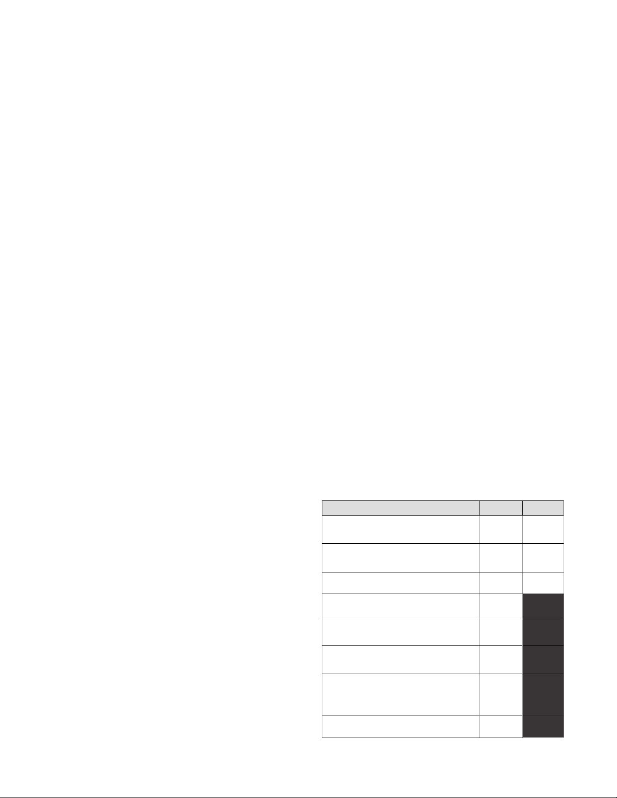
PRODUCTS PARTS LABOR
Star Ultra-Max® griddles,
charbroilers, and hotplates 2years 2years
Star-Max® fryers, griddles,
charbroilers, and hotplates 2 years 2 years
Jetstar® popcorn poppers 2 years 2 years
Staltek™ roller grill coatings 5 years
chrome griddle surfaces [against
peeling] 5 years
cast iron grates, burners,
and burner shields 180 days
original Star or Toastmaster parts
sold to repair Star or Toastmaster
equipment
90 days
The foregoing warranty is in lieu of any and all other warranties expressed or implied and constitutes the entire warranty. 2M-Z21647 • Rev C• 02.2018
Service First 1year

These symbols are intended to alert the user to the presence of
important operating and maintenance instructions in the manual
accompanying the appliance.
RETAIN THIS MANUAL FOR FUTURE REFERENCE
NOTICE
Using any part other than genuine Star factory supplied parts relieves the
manufacturer of all liability.
Star reserves the right to change specications and product design without
notice. Such revisions do not entitle the buyer to corresponding changes,
improvements, additions or replacements for previously purchased
equipment.
Due to periodic changes in designs, methods, procedures, policies and
regulations, the specications contained in this sheet are subject to change
without notice. While Star International Holdings Inc., Company exercises
good faith efforts to provide information that is accurate, we are not
responsible for errors or omissions in information provided or conclusions
reached as a result of using the specications. By using the information
provided, the user assumes all risks in connection with such use.
MAINTENANCE AND REPAIRS
Contact your local authorized service agent for service or required maintenance.
Please record the model number, serial number, voltage and purchase date in the area below and have it
ready when you call to ensure a faster service.
SAFETY SYMBOL
Model No.
Serial No.
Voltage
Purchase Date
Business 8:00 am to 4:30 p.m. Central Standard Time
Hours:
Telephone: (314) 678-6303
Fax: (314) 781-2714
E-mail [email protected]
Website: www.star-mfg.com
Service Help Desk
Authorized Service Agent Listing
Reference the listing provided with the unit
or
for an updated listing go to:
Website: www.star-mfg.com
E-mail [email protected]
Mailing Address: Star Manufacturing International Inc.
265 Hobson Street
Smithville, TN 37166
U.S.A
1

SPECIFICATIONS
UM1833A-208V, UM1833A-240V
6,400 Watts (6,000 element), 32/29 Amps at 208/240VRating/Connection:
Electrical Supply:
NEMA 6-50 plus with six foot oil-resistant cord
Separate 50 Amp 208/240VAC, single phase, 50/60 Hz service per Oven
Approximate Weight: Lbs (81.8 Shipping - 2101833 Lbs- 180Oven with kg),( 95.5(Legs): Installed kg)
Dimensions: Width: 51.2" (130.0 cm) - Oven with Shelves
Depth: 30.4" (77.2 cm)
Height: 20.0" (50.8 cm) - Single Oven with Legs
36.0" (91.4 cm) - Double Oven with Legs
Recommended Minimum Clearances:
0" (0 cm)Rear of Oven to Wall
Conveyor Extensions to Wall 6" (15.2 cm)
UM1850A-208V, UM1850A-240V
6,400 Watts (6,000 element), 32/29 Amps at 208/240VRating/Connection:
Electrical Supply:
NEMA 6-50 plus with six foot oil-resistant cord
Separate 50 Amp 208/240VAC, single phase, 50/60 Hz service per Oven
95.5 kg),(Lbs- 210 Shipping - 240 Lbs (109.1InstalledLegs):withOven1850(Approximate Weight kg)
Dimensions: Width: 50.0" (127.0 cm)
Depth: 30.4" (77.2 cm)
Height: 20.0" (50.8 cm) - Single Oven with Legs
36.0" (91.4 cm) - Double Oven with Legs
Recommended Minimum Clearances:
0" (0 cm)Rear of Oven to Wall
Conveyor Extensions to Wall 6" (15.2 cm)
UM1833A-230V
Rating/Connection: 6,600 Watts (3 x 2,000W element assembly)
Terminal block supplied (L1, L2, L3, N, Ground)
Electrical Supply: Separate service per oven - 15 Amp, 400/230 VAC, 3 phase, 50 Hz
Approximate Weight (1833 Oven with Legs): Installed - 180 Lbs (81.8 kg), Shipping - 210 Lbs (95.5 kg)
Dimensions: Width: 51.2" (130.0 cm) - Oven with Shelves
Depth: 30.4" (77.2 cm)
Height: 20.0" (50.8 cm) - Single Oven with Legs
36.0" (91.4 cm) - Double Oven with Legs
Recommended Minimum Clearances:
0" (0 cm)Rear of Oven to Wall
Conveyor Extensions to Wall 6" (15.2 cm)
UM1850A-230V
Rating/Connection: 6,600 Watts (3 x 2,000W element assembly)
Terminal block supplied (L1, L2, L3, N, Ground)
Electrical Supply: Separate service per oven - 15 Amp, 400/230 VAC, 3 phase, 50 Hz
Approximate Weight (1850 Oven with Legs): Installed - 210 Lbs (95.5 kg), Shipping - 240 Lbs (109.1 kg)
Dimensions: Width: 50.0" (127.0 cm)
Depth: 30.4" (77.2 cm)
Height: 20.0" (50.8 cm) - Single Oven with Legs
36.0" (91.4 cm) - Double Oven with Legs
Recommended Minimum Clearances:
0" (0 cm)Rear of Oven to Wall
Conveyor Extensions to Wall 6" (15.2 cm)
2

SPECIFICATIONS
3
B
A = 51.2 (1300)
A1= 50.0 (1270)
A2= 33.0 (838)
B = 30.4 (772)
C = 16.0 (406)
C1= 20.0 (508)
A1
C1
10.6 [269]
21.0 [533]
22.0 [559]
STACKED DIMENSION
= C + C1
UM1850
24.1 [612]
UM1833 WITH
INFEED/EXIT SHELVES
C
A
8.2
[208]
CONTROL BOX
DOOR OPEN
14.5
[369]
END VIEWFRONT VIEWS
TOP VIEW
1833 W\OUT
SHELVES SHOWN
A2
14.5 [369] 11.4 [291]
2.0 [51]
00
0

GENERAL INFORMATION
This equipment is designed and sold for commercial use only by personnel trained and experienced
in its operation and is not sold for consumer use in and around the home nor for use directly by the
general public in food service locations.
First and foremost, each crate should be examined before signing the Bill of Lading to report any
visible damage by the trucker in transit and to account for the proper number of crates. If there
is apparent damage, arrangements should be made to le a claim against the carrier. Interstate
Commerce Regulations require that the claim must be initiated by the consignee. Proper and secure
storage facilities should be arranged for the oven(s) if necessary to protect it from outdoor or damp
conditions at all times before installation.
-IMPORTANT-
When you have all the crates unloaded, open the crates and remove all plastic covers.
Inspect at once for concealed damage. If anything appears to be damaged, contact the
appropriate persons immediately to le a damage claim. After completing this inspection,
nish unpacking the oven. Be sure to remove all paper protection and packing material
from the unit prior to heating.
CAUTION
FOR YOUR SAFETY DO NOT STORE OR USE GASOLINE OR OTHER FLAMMABLE
VAPORS AND LIQUIDS IN THE VICINITY OF THIS OR ANY OTHER APPLIANCE.
THIS APPLIANCE MUST BE INSTALLED BY QUALIFIED PERSONS AND INSTALLED IN
ACCORDANCE WITH THE RULES IN FORCE WITHIN THE COUNTRY OF DESTINATION.
INSTALLATION
208 V and 240 V models
The ovens are equipped for the voltage indicated on the nameplate mounted on the rear of the
control box. They will operate on alternating current (AC) only. A cord is provided with a NEMA 6-50
plug. A matching receptacle with 50A supply must be provided.
230 V models
The ovens are equipped for the voltage indicated on the nameplate mounted on the rear of the
control box. They will operate on alternating current (AC) only. A cord bushing is supplied in the
bottom of the control box. This allows the installer-supplied cord to be connected to the terminal
block connections located behind the rear access door. The oven must be connected to power per all
applicable codes. A means of disconnecting the oven from power should be supplied for safety and
ease of maintenance.
The appliance must be positioned so the plug is accessible. A harmonized, 300/500V, oil-resistant,
flexible cord with 65°C minimum ratings must be used. Choose appropriate conductors in relation to
the length of the cord (1.0 square mm minimum) and operating conditions (e.g. temperature).
WARNING
DO NOT CONNECT TO DIRECT CURRENT (DC) POWER.
The installation of the electric oven should conform to the:
NATIONAL ELECTRIC CODE AND ALL LOCAL ELECTRIC CODES AND
ORDINANCES AND THE LOCAL ELECTRIC COMPANY RULES AND
REGULATIONS.
PURCHASER'S RESPONSIBILITY
It is the responsibility of the purchaser:
1. Toseethattheelectricservicesfortheovenareinstalledon site in accordance with the manufacturer's
specications.
2. To unload, uncrate, and install the oven in its proper location and in accordance with this installation
operation manual.
3. To see that electric services are connected properly by a qualied installer of your choice. All such
connections must be in accordance with applicable code requirements.
4. To arrange for inspection and operation check-out by an authorized service technician. The
warranty becomes effective upon verication of proper installation.
4

IMPORTANT SAFETY INFORMATION
Do not attempt to operate the oven until connection of utility service has been fully inspected by an
authorized service technician or a Star Service Representative. This service is required by Star in
order to assist the purchaser in proper start-up of the oven on site. Please note the specic details on
the Warranty and make certain that service connections are made to proper utility services.
The warranty shall not apply if the oven is started up and operated prior to the utilities and oven being inspected and
check-out made by an authorized service technician or a Star Service Representative.
CAUTION
IMPROPER INSTALLATION, ADJUSTMENT, ALTERATION, SERVICE, OR MAINTENANCE
CAN CAUSE PROPERTY DAMAGE, INJURY, OR DEATH. READ ALL INSTRUCTIONS
THOROUGHLY BEFORE INSTALLING OR SERVICING THIS EQUIPMENT.
CAUTION
Minimum clearances must be maintained from all walls and combustible materials.
Minimum clearances for this unit should be 0 inches from the rear (rear bumpers provided
must be in place) and 6 inches from both sides. Keep the oven free and clear of all
combustible material.
CAUTION
Do not obstruct the ventilation holes in the control panels as these provide cooling
air for the controls.
WARNING
The oven is to be operated only on the type of electricity shown on the specication plate.
INSTALLATION INFORMATION
THE INSTALLATION INSTRUCTIONS CONTAINED HEREIN ARE FOR THE USE OF
QUALIFIED INSTALLATION AND SERVICE PERSONNEL ONLY. INSTALLATION OR
SERVICE BY OTHER THAN QUALIFIED PERSONNEL MAY RESULT IN DAMAGE TO THE
OVEN AND/OR INJURY TO THE OPERATOR.
Qualied installation personnel are individuals, a rm, a corporation, or a company which either in
person or through a representative are engaged in and responsible for:
1. The installation of electrical wiring from the electric meter, main control box, or service outlet to
the electric appliance.
Qualied installation personnel must be experienced in such work, familiar with all
precautions required, and have complied with all requirements of state or local authorities
having jurisdiction.
LOCATION
The well-planned and proper placement of your oven will result in long-term operator
convenience and satisfactory performance.
It is essential that an adequate air supply to the oven be maintained to provide a sufcient
ow of ventilation air. Follow these guidelines:
1. Place the oven in an area that is free of drafts.
2. Keep the oven area free and clear of all combustibles such as paper, cardboard, ammable liquids,
and solvents.
3. Do not place the oven on a curb base or seal to a wall. This will restrict the ow of air and prevent
proper ventilation to the blower motors. This condition must be corrected to prevent permanent
damage to the oven.
4. On all models, tripping of the blower motor's thermal overload device indicates an excessive
ambient temperature at the back of the oven. This condition must be corrected to avoid permanent
damage to the oven.
5

6
CAUTION
Any surface the oven is mounted on should have a raised area around the perimeter to
prevent the oven from accidentally sliding off the edge. Serious injury or death could
occur if the oven falls on a person.
CAUTION
Any cart that the oven is mounted on must be deep and wide enough to provide a stable
platform. A cart with a narrow stance could allow the oven to tip over, causing property
damage or serious harm to people.
VENTILATION
Local codes prevail. These are the "authority having jurisdiction" as stated by the National Fire
Protection Association, Inc. in NFPA 96-Latest Edition. For further ventilation information see below.
A ventilation hood may be required to remove heat and cooking odors. The hood and HVAC
installation must meet local codes to gain approval by the authority having jurisdiction. Requirements
may vary throughout the country depending on the location by city, county, and state. Obtain
information from the authority having jurisdiction to determine the requirements for your installation.
Obtain information and review copies of codes or documents that will be used to inspect and approve
your installation. Your ventilation hood supplier and HVAC contractor should be contacted to provide
guidance.
CAUTION
Prevent airow through the cooking tunnel. Air must NOT be directed onto the oven's
front or rear or to the sides of the cooking area. This can cause incomplete or uneven
baking and increased energy consumption.
ELECTRICAL CONNECTION
Before making any electrical connections to this unit, check that the power supply is adequate for the
voltage, amperage, and phase requirements stated on the rating plate. A wiring diagram is included
herewith.
When installed, this appliance must be electrically grounded and its installation must comply with
the National Electric Code, ANSI-NFPA 70, latest version, manufacturer's installation instructions,
and applicable local municipal building codes. In Canada, all electrical connections are to be in
accordance with CSA C22.1 - Canadian Electrical Code Part 1 and/or local codes.
WARNING
208 V and 240 V
This appliance is equpped with a three-prong (grounding) plug for your protection against
shock hazard and should be plugged directly into a properly grounded three-prong
receptacle. Do not cut or remove the grounding prong from this plug.
230 V
This appliance is equipped with a five-pole terminal and cord bushing to which the
customer/installer can attach. Each line (L1, L2, L3) should have 230 V potential
referenced to the neutral (N) connection. An earth (ground) connection is also provided
for a five-wire system.
This appliance must be installed on a sturdy
counter or stand using the feet provided
for cleaning clearance. As a minimum, 24"
of clearance on the discharge end of the
oven should be allowed for removal of the
conveyor assembly if the oven is not on a
mobile cart. Also allow room for a service
technician to access the control box door
and the fan motor cover over the rear of the
oven if the oven is not movable.

7
STACKING INSTRUCTIONS
The following instructions should be followed when stacking
more than one unit.
Single Oven (or Bottom) Cart Install:
1. Remove door, conveyor, and nger assemblies.
2. Unbolt unit from shipping crate (2 bolts).
3. Turn unit on front as shown.
4. Thread the four legs into the bottom of the oven.
5. CAREFULLY lift oven upright.
Stacked Oven Install Preparation:
1. Remove door, conveyor, and nger assemblies.
2. Unbolt unit from shipping crate (2 bolts).
3. Turn unit on front as shown.
4. Remove top of lower oven (4 screws total, 2 each front and rear)
and bolt to stacked oven base using 3/8 - 16 bolts.
5. Place top oven on lower unit and re-attach with screws for top of
lower oven.
OPERATING INSTRUCTIONS
DO NOT ATTEMPT TO OPERATE THE OVEN until connection of
utility service and installation has been fully inspected (start-up check-
out) by an authorized service technician or a Star Service Technician
in order to assure the oven is properly installed and in working order.
The warranty becomes effective upon verication of proper
installation.
Unless specied otherwise, conveyor travel is factory set for left to right operation when facing the
front of the oven. If a direction change is required, refer to "DISPLAY INFORMATION," section 3 for
instructions on how to program the controller for a direction change. In addition, the conveyor belt
must be changed to travel in the new direction.
SAFETY OPERATING INSTRUCTIONS
The information contained in this section is provided for the use of qualied operating personnel.
Qualied operating personnel are those who have carefully read the information contained in this
manual, are familiar with the functions of the oven and/or have had previous experience with the
operation of the equipment described. Adherence to the procedures recommended herein will assure
the achievement of optimum performance and long, trouble-free service.
CAUTION
DO NOT WORK AROUND THE CONVEYOR BELT
WITH LONG HAIR, LOOSE CLOTHING, OR DANGLING
JEWELRY. GETTING CAUGHT IN THE BELT COULD
RESULT IN DISMEMBERMENT OR FATAL INJURY.

Please take time to read the following safety operating instructions. They are the key to the
successful operation of your Ultra-Max Conveyor Oven.
SAFETY TIPS
For your safety, read before operating.
If you smell gas:
1. DO NOT try to light any appliance.
2. DO NOT touch any electrical switches.
3. Use anexteriorphonetocallyourgassupplier
immediately.
4. If you cannot reach your gas supplier, call
the re department.
In the event of a power failure:
1. Turn all switches off.
2. DO NOT attempt to operate the oven until
the power is restored.
8
IL3046
®
SELECTING COOK OPTIONS:
1. PRESS & HOLD FOR 1/2 SECOND.
2. PRESS REPEATEDLY TO CHOOSE YOUR COOKING OPTION.
3. PRESS TO ACCEPT OR WAIT AND SETTINGS WILL RESET.
Consult the manual for instructions to change option settings.
Consultez le manuel pour les instructions pour modifier les parametres d’ options.
’
Comment selectionner des options:
1. Appuyez maintenez pendant 1/2 seconde.
2. Appuyez sur a plusieurs reprises pour les options.
3. Appuyez sur pour accepter ou attendre rearmement automatique.
’
’
’
General Safety Tips:
1. If the oven needs to be moved for any reason,
the power must be disconnected from the unit
before doing so.
2. DO NOT remove the control box cover unless
the oven is unplugged.
OPERATION
To turn the oven on:
1. Push the power switch to "ON."
2. After the fan begins to buildpressure, the pressure
switch will provide power to the control board
to engage the heating element contactor. You
should hear an initial "click" from the contactor
as it begins to heat.
To adjust the time and temperature:
1. Press the DOWN and UP arrows
( ) at the same time. Hold for four seconds
until the TIME display goes blank.
2. Press the ENTER button ( ) to switch between
TIME and TEMPERATURE.
3. Press the UP arrow ( ) to increase or the
DOWN arrow ( ) to decrease the TIME or
TEMPERATURE. Hold either button down for
faster display changes.
4. After ve seconds, the new numbers will be saved
and the oven will display the new settings.
SELECTING COOKING OPTIONS
1. Press & hold for 1/2 second.
2. Press repeatedly to choose your cooking
option.
3. Press to accept or wait and setting will reset.
To turn the oven off:
1. Push the power switch to "OFF." The oven is
equipped with a cool-down feature for motor shaft
and bearing protection. This enables the blower
motor(s) to run regardless of the controller status.
The blower(s) continue to run until the oven cools
to a safe temperature.
COOKING OPTION
OPTION TEMP TIME
1 500°F/260°C 8:00
2 400°F/204°C 14:00
3 450°F/232°C 16:00
4 500°F/260°C 10:00
5 450°F/232°C 12:00
6 400°F/204°C 20:00

9
DISPLAY INFORMATION
When operating the oven, there are three levels of access:
1. Store Level - General employees would know these functions and how to change them. While the
oven is running, enter this mode by holding the DOWN and UP arrows ( ) simultaneously for
four seconds. The TIME display goes blank and the TEMP setpoint is displayed. Adjust with the
DOWN or UP arrows. The ENTER button ( ) toggles between TIME and TEMP. The parameter
that can be adjusted is displayed, the other is blank. When TIME and TEMP are adjusted as
needed, wait ve seconds and SAVE is displayed. The values are accepted and the controller
begins controlling to these new values. The conveyor continues to operate at the same speed
until a new value is accepted. The temperature control output should be OFF during changes.
2. Manager Level - This is a lock so that TIME and TEMP cannot be changed even at
the Store Level. While the oven is running, enter this mode by holding the DOWN and
UP arrows simultaneously for 4 seconds. The TIME display goes blank and the TEMP
setpoint is displayed. Release the UP arrow and continue to hold the DOWN arrow for
an additional 4 seconds. The TEMP display shows LOC as the TIME display shows
nO, which indicates that the TIME/TEMP parameters can be changed after reaching the
STORE level. yES indicates that the parameters cannot be changed even after entering
the STORE level. The LOC setting can be toggled using the ENTER button ( ).
ADDITIONAL FUNCTIONS
The conveyor belt direction and the temperature display can be changed on the conveyor oven by
a qualied technician. To change the belt direction, the technician must reverse the motor direction
and rotate the conveyor belt for proper oven function. A technician can also change the temperature
display from Fahrenheit to Celsius. These changes can be made by the technician during the start-
up/check-out or at a later date.
ERROR CODES
Error codes will display as ashing text messages for diagnostic purposes. Any temperature or
thermocouple error should turn the temperature output OFF and leave the conveyor running at the
same speed. The belt error should turn the temperature output OFF. The speed error should display
when the motor is unable to settle at the chosen speed. This might occur if a fast speed is chosen
that the motor is unable to spin fast enough to achieve. The speed signal output will remain the same
but the display will ash the error message.

BAKE TIME VERSUS TEMPERATURE
1. Bake time is actually conveyor speed and is dened as the time the product is actually in the oven.
This is measured by noting the time when the leading edge of the product enters the oven and
the time the leading edge of the product leaves the oven. This is adjusted by using the conveyor
speed controller.
2. Bake temperature is adjusted by changing the setpoint of the temperature controller to the
desired bake temperature. When the oven reaches the desired temperature, the red dot in the
lower right corner of the temperature display will turn off and on as the controller maintains the
temperature.
3. When establishing a bake time and temperature for a given product, the general rule shall be as
the bake time increases the bake temperature decreases and the reverse is also true; increase
temperature, decrease time. However, there are limits to the above rule. Going to extremes
will result in a burnt exterior and raw interior or it will result in a very light color but over-baked
product.
4. Once a good bake has been established, the ne adjustments should be made by holding either
the bake time or bake temperature constant, then varying the other.
CONVEYOR SPEED
Bake Time (Conveyor Speed) - As stated previously, bake time (conveyor speed) is dened as the
amount of time elapsed between the time the leading edge of the product enters the oven and the
leading edge of the product exits the oven. Bake time is controlled by adjusting the digital speed
controller. The setting on the control panel indicates the actual bake time.
Bake time will be the same for any size product.
TIME OF DELIVERY
The time of delivery is the amount of elapsed time between the period when the leading edge of the
product enters the oven and the trailing edge of the product is fully discharged and is ready to be
delivered to the customer.
Time of delivery changes if the product size changes.
Tip: Train yourself not
to pull the product out
of the oven when the
leading edge comes
out. Always wait until
the entire product has
passed under the air
nozzle holes - the
product needs this time
to fully bake.
10
BAKE vs. DELIVERY TIME
Time to Delivery changes with product
but Bake Time remains constant
at a steady conveyor speed.
24 (BAKE)
32 (DELIVERY)
40 (DELIVERY)
6:00 (BAKE)
8:00 (DELIVERY)
10:00 (DELIVERY)

CLEANING INSTRUCTIONS
Follow this recommended cleaning schedule for proper oven performance:
CAUTION
DISCONNECT THE POWER SUPPLY BEFORE SERVICING OR CLEANING THIS OVEN.
SAFEGUARD THE POWER SO IT CANNOT BE ACCIDENTALLY RESTORED. FAILURE TO DO SO
COULD RESULT IN DISMEMBERMENT, ELECTROCUTION, OR FATAL INJURY. THERE IS MORE
THAN ONE POWER SUPPLY CONNECTION POINT WHEN OVENS ARE STACKED, SO MAKE
SURE THAT ALL SWITCHES ARE IN THE OFF POSITION BEFORE CLEANING OR MAINTENANCE.
No electrical components should be subjected to moisture. It is therefore important that the oven is wiped
down carefully. NEVER throw buckets of water over the oven or subject it to pressure washing from a
hose or a pressure spray. If water or other liquid is spilled on the oven, make sure that none of it has
entered the control box area before switching the oven ON. If in doubt, call your service company.
CAUTION
Adhere to the following warnings when cleaning or maintaining your conveyor oven:
1. The oven must be cool. Do not use power cleaning equipment, steel wool, or wire brushes on
stainless steel surfaces.
2. Do not use a caustic or an alkaline base cleaner on the interior of the oven.
This will ruin the aluminized nish of the oven interior.
3. When using cleaning solutions, be sure they meet local and national health standards.
DAILY
1. Clean the conveyor belt using a nylon brush. Allow any foreign material to drop into the crumb
pans.
2. Empty and clean the crumb pans. Use a hot water and detergent mix.
Rinse with clean water.
EVERY MONTH
1. Brush and clean the guard on the motor cooling fan.
2. Unplug the oven.
3. Remove the crumb pans.
4. Remove the conveyor assembly.
5. Unlatch and remove the front door. First remove all Baffles then Finger Assemblies.
See instructions next page.
6. Clean the oven interior with an appropriate oven cleaner.
7. Clean the conveyor assembly, crumb pans, and other removable components.
Wash in a hot water, detergent mix and rinse with clean water. For difcult cleaning areas, use a
heavy-duty de-greaser or oven cleaner.
8. Move the oven and clean under it. Be careful not to damage the oven's electrical cord or plug when
moving.
9. Reassemble the oven, being certain to include all Finger Assemblies and the Upper & Lower
Bafes.
Be certian the Lower Bafe Flange is properly positioned behind the Rear Oven Wall, as well
as the Upper Bafe is in position against the Upper Bafe Seat, as shown.
EVERY TWELVE MONTHS
A factory authorized service person should:
1. Open and clean the inside of the control box.
2. Check and tighten all electrical components.
If maintenance is required, contact your local service company, a factory representative, or
Star Manufacturing.
11

12
Bafe & Finger Removal / Installation
123
IL1190
4
LOWER BAFFLE
UPPER BAFFLE
Removing Finger Assemblies
1. Once cooled, REMOVE conveyor assembly and door.
2. Life up and remove Upper & Lower Bafes as shown in Step 1.
3. Slide Finger Assembly out of unit as shown in Step 2.
4. Lift Assembly apart as shown in Step 3. and wash in a hot water, detergent mix and rinse
with clean water. For difficult cleaning areas, use a heavy-duty de-greaser or oven
cleaner.
Reassemble Finger Assemblies
1. Reassemble nger assemblies and install in unit.
2. Properly install Bafes as shown in Step 4.
CAUTION
BE CERTAIN THE LOWER BAFFLE IS PROPERLY INSTALLED BEHIND THE REAR PANEL
SO NOT TO INTERFERE OR DAMAGE CONVEYOR ASSEMBLY.
3. Reinstall conveyor & door assembly, and test unit for proper operation.

CONVEYOR BELT TENSION
The conveyor belt of the Ultra-Max Conveyor Oven
does not have a tension adjustment. If the belt
becomes too loose, a link will have to be removed
to tighten. A belt that is too tight will also cause
operational problems due to excessive drag. We
suggest that you have a qualied service technician
perform this adjustment.
CAUTION
Careful consideration should be exercised prior to
removing a belt link because a belt that is too tight
will impede the smooth operation of the conveyor.
CONVEYOR BELT LINK REMOVAL
An entire link can be removed with the conveyor assembly
either in or out of the oven. This may be necessary as
the belt stretches after continuous use. Following are the
necessary steps for removing links:
1. Move the splice clips to either end of the oven for easy
access.
2. Unhook the splice clips using long nose pliers.
3. Unhook the full link to be removed and slide it out.
Do not discard the link removed as it may be used for
making spare splice clips.
4. Reconnect the inside splice clips.
5. Reconnect the outside splice clips.
6. Replace all parts removed from the oven.
7. Straighten any bent wires to ensure smooth sprocket
engagement.
13
Remove the outside master links on the right and left
sides of the conveyor belt. Remove the center splice
clips next.
Unhook the end loop and pull up on the link section.
Save this link as it may be used for making splice
clips.
Check the orientation of the splice clips (the hooks
should be up). The belt shown is the top section,
ready for left-to-right travel.

L1
L2
G I I
e
?◊
�
,.
m
o� 01
SECOND GENETION I
m
I
I
I
I
I
1
STAR MANUFACTURING INTERNATIONAL, INC.

INCLUDE THIS PRINTED DIAGRAM
W/ MANUAL & INSTALLATION INFO
◄
z
¢
MODEL: UME
r----------7
0 QI
� I
D I
I
I
I
I
4•�
STAR MANUFACTURING INTERNATIONAL, INC.
2M-Z13288 rev B 01-31-2018 DR: JT

I
208-24�B-240v
208-240v
G
I
?◊
�
f�95
V
31----------------
QocB Qi
m
CN1I
CN1�
<
___
GR
"
�o
�M
z
Zo
�i
z
Z
5�
-0
r
Mb
z
I�
0
►
_
z
z
'
l
c
0
<Z
o
z
z
I

1,2: AC IN
3: FG
4,5: -V OUT
6,7: +V OUT
1 24VDC RETURN (COMMON)
7 +24VDC
2 DIRECTION
3 ENABLE (ACTIVE LOW)
4 FAULT (ACTIVE LOW)
5 COMMON
6 COMMON
8 TACH (12 PPR)
9 VOLTAGE INPUT (SPEED)
10 +5V (USE FOR SPEED POT ONLY)
11 BRAKE (ACTIVE LOW)
12 COMMON
PS
XF1
GM/C
GM/C
C1
DSIC
PS
M1
OCB
TS1
TL2
TL1
CB
SE
FS
DS
S1
XF1
CON
TB
CB
- GEARMOTOR & CONTROLLER
- CAPACITOR, CIRC FAN MOTOR
- DIRECT SPARK IGNITION CONTROLLER
- POWER SUPPLY, 24VDC 150W PS
- MOTOR, CIRC FAN
- OVEN CONTROL BOARD
- COOL DOWN T-STAT
- CONTROL BOX TEMP LIMIT (MAN RESET)
- COOK CHAMBER TEMP LIMIT (BULB & CAP)
- CIRCUIT BREAKER
- SPARK ELECTRODE
- FLAME SENSOR
- DIFFERENTIAL PRESSURE SWITCH
- SWITCH, MAIN
- TRANSFORMER, 230V-24V
- CONTACTOR
- TERMINAL BLOCKS (2)
- CONNECTION BLOCK
TL1
TS1
TL2
41 361320
12
3
4
5
6
7
20
27
28
X
X
X12
11
10
9
8
71
2
3
4
5
6
13
42
29
X
X
12
BLK
BRN
BLU
M1
C1
TL2
TS1
6
4
2
13 5
24V
L2 L1
7
19
7
6
DS
32
2
S1
8
30
15
25
14
TB
5
4
_
8 9
36
10
_
19
21
41
21
_
_
_
30
18
BLU
15
9
32
SET VOLTAGE TO 230V
BEFORE INSTALLING
46
3
3325
17
BLK BRN
L3
14
3938
34 23
PLUG ON BACK OF MOTOR
IS SHOWN ROTATED 180°
T/C
L2 CONTACTOR
10 PR 17
208V
230V
"L" "H"
DS
CNC
NO
FUSE BLOCK
(2) @ 5A
18
1
3x2000W COILS J1
J1
14
38
39
40
16
L1
40
16
37
37
NOTES:
FOR FIELD WIRING BY INSTALLER WITH CORD OR FLEXIBLE
CONDUIT. (2) EXTRA J1 JUMPERS FOR SINGLE PHASE USE
(TIE L1,L2,L3 TOGETHER) WRAP THESE WITH OTHER LOOSE
SHIP PARTS
N L3 L2 L1
3
54 2 1
45
44
43
46
43
44
45
4
C
42
CN3
TO MOTOR
6 = COM
5 = ENABLE
4 = DIR
3 = SPEED
2 = COM
1 = TACH
27
28
12
1
CN3
X
29
CN5 TO
SMALL MOTOR
7 = SPEED (GRD)
6 = SPEED SIGNAL
5 = SPEED (5V REF)
4 = (NOT USED)
3 = TACH (GND)
2 = TACH (+5V)
1 = TACH SIGNAL
OCB
SECOND GENERATION
1CN1 T/C TYPR K
YEL(+) RED(-)
SH (SHIELD)
CN1
CN2 (24V)
INPUT
2 = N
1 = H
CN4 _
1
23
34
CN2 133
25
CN4
OUTPUT TO
SOLENOID
3 = COM
2 = 24V
1 = N/C
R
RDL
A 09/15/03
B 03/26/04 RDL
C 9/23/04 CG
MATERIAL
DR.D
FINISH
MODEL NO.
TITLE
PART NO.
STAR MFG. INTERNATIONAL, INC.
#10 SUNNEN DRIVE, ST. LOUIS, MO. 63143, USA
TOLERANCES UNLESS OTHERWISE NOTED
FRACTIONS ±1/64 DECIMALS ±.005 ANGLES ±1°
THIS DRAWING CONTAINS INFORMATION CONFIDENTIAL TO STAR MFG. INT'L INC.
NO REPRODUCTION OR DISCLOSURE OF ITS CONTENTS IS PERMITTED.
DESCRIPTION OF CHANGE
REVISIONS
CK.
---
---
UM-1833
SK-1987
WIRING DIAGRAM, 400/230
R.
RDL 04/30/03 LTR DATE
DATE
BL
ADD 2ND GENERATION CONTROLLER
SHOW BEND IN T/C FOR NEW MOUNT
UPDATED OVEN CONTROL BOARD
TL1

1,2: AC IN
3: FG
4,5: -V OUT
6,7: +V OUT
1 24VDC RETURN (COMMON)
7 +24VDC
2 DIRECTION
3 ENABLE (ACTIVE LOW)
4 FAULT (ACTIVE LOW)
5 COMMON
6 COMMON
8 TACH (12 PPR)
9 VOLTAGE INPUT (SPEED)
10 +5V (USE FOR SPEED POT ONLY)
11 BRAKE (ACTIVE LOW)
12 COMMON
PS
XF1
GM/C
TL1
TS1
TL2
361320 41
12
3
4
5
6
7
20
27
28
X
X
X12
11
10
9
8
71
2
3
4
5
6
13
42
29
X
X
12
BLK
BRN
BLU
M1
C1
TL1
TL2
TS1
6
4
2
13 31
24V
L2 L1
7
19
26
6
DS
32
2
S1
8
30
15
25
14
TB
7
4
_
8 9
36
10
41
19
21
33
11
25
22
24
30
18
BLU
15
9
32
SET VOLTAGE TO 230V
BEFORE INSTALLING
GND
3
1122
17
BLK BRN
L3
L2
43
PLUG ON BACK OF MOTOR
IS SHOWN ROTATED 180°
T/C
CONTACTOR
10 PR 17
208V
230V
"L" "H"
DS
CNC
NO
FUSE BLOCK
(2) @ 5A
18
1
COILS:
3x2000W
14
39
40
16
L1
NOTES:
FOR FIELD WIRING BY INSTALLER WITH CORD OR FLEXIBLE CONDUIT.
(2) EXTRA J1 JUMPERS FOR SINGLE PHASE USE (TIE L1,L2,L3 TOGETHER)
WRAP THESE WITH OTHER LOOSE SHIP PARTS
4
42
CN3
TO MOTOR
6 = COM
5 = ENABLE
4 = DIR
3 = SPEED
2 = COM
1 = TACH
27
28
12
1
CN3
X
29
CN5 TO
SMALL MOTOR
7 = SPEED (GRD)
6 = SPEED SIGNAL
5 = SPEED (5V REF)
4 = (NOT USED)
3 = TACH (GND)
2 = TACH (+5V)
1 = TACH SIGNAL
OCB
SECOND GENERATION
1CN1 T/C TYPR K
YEL(+) RED(-)
SH (SHIELD)
CN1
CN2 (24V)
INPUT
2 = N
1 = H
CN4 _
1
23
34
CN2 133
25
CN4
OUTPUT TO
SOLENOID
3 = COM
2 = 24V
1 = N/C
38
L3
L2 CONTACTOR
L1
3938 40
44 45
J1
J1
J1
23
34
14
16
BLK
WHT
RED
31
24
26
208V
208V
208V
CUSTOMER INSTALLED
POWER INLET:
CORD CONNECT OR HARDWIRE
TO DEDICATED 20A 3-PHASE
CIRCUIT.
JUMPER #21 NOT USED
TAPE UNUSED CONNECTOR
GM/C
C1
DSIC
PS
M1
OCB
TS1
TL2
TL1
CB
SE
FS
DS
S1
XF1
CON
TB
CB
- GEARMOTOR & CONTROLLER
- CAPACITOR, CIRC FAN MOTOR
- DIRECT SPARK IGNITION CONTROLLER
- POWER SUPPLY, 24VDC 150W PS
- MOTOR, CIRC FAN
- OVEN CONTROL BOARD
- COOL DOWN T-STAT
- CONTROL BOX TEMP LIMIT (MAN RESET)
- COOK CHAMBER TEMP LIMIT (BULB & CAP)
- CIRCUIT BREAKER
- SPARK ELECTRODE
- FLAME SENSOR
- DIFFERENTIAL PRESSURE SWITCH
- SWITCH, MAIN
- TRANSFORMER, 230V-24V
- CONTACTOR
- TERMINAL BLOCKS (2)
- CONNECTION BLOCK
UM-1833
2M-Z11885 Rev. - 9/8/2008
WIRING DIAGRAM, 3PH, 4-WIRE
Other manuals for Holman Ultra-Max UM1833A
1
This manual suits for next models
1
Table of contents
Other Star Oven manuals

Star
Star Holman Ultra-Max UM1833A User manual

Star
Star Ultra-max UM3240 User manual

Star
Star Ultra Max UM1833A Installation instructions

Star
Star 318HX Series User manual

Star
Star Holman Turbo-Max HSCO14 User manual

Star
Star Ultra Max UM1833A-208V Installation instructions

Star
Star Holman Ultra-Max UM1854 User manual

Star
Star Holman Ultra-Max UM-1833 User manual