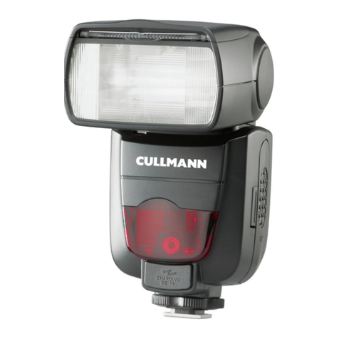
Starblitz 3200BT-TWIN-S User manual

Starblitz
3200BT-TWIN-S
INSTRUCTIONS
MODE
D'EMPLOI
GEBRAUCHSANWEISUNG
ISTRUZIONI

>
PARTS
DESCRIPTION
1.
2.
Flash
window
Adjustable
bounce
(up-
down)
head
Ajustable
swivel
(right-
left)
base.
Battery
door
ON-OFF
(1-0)
switch
for
Mini-Flash
Flash
window
of
Mini-Flash
Auto
sensor
eye
3
position
switch
Synchro
cable
socket
Shoe
lock
screw
wl
Hot
shoe
contact
Synchro
cable
Green
Auto
Check
Lan
Bounce
(up-down)
ang
cator
Illumination
Guide
Dia
Ready
Neon
Lamp
"MANUAL
OFF”
PUSH
SWI]
"POWER
ON’
PUSH
SW
TEST
BUTTON
FILTERS
KIT
(WIDE-ANG
GREEN,
RED,
ORANGE

SPECIFICATIONS
Guide
Number
:
Coverage
Distances
:
Colour
Temperature
:
Angle
of
Coverage
:
Flash
Duration:
Recycling
Time:
Power
Source
:
Number
of
Flashes
:
Dimensions
:
Weight
:
1)
By
Main
Flash
Only
30
in
meter
ASA
100
50
in
feet
ASA
25
2)
By
Dual
Flashes
a)
By
Main
Flash
25
in
meter
ASA
100
41
in
feet
ASA
25
b)
By
SUB/MINI
Flash
6
in
meter
ASA
100
10
in
feet
ASA
25
c)
By
Dual
Flashes
26
in
meter
ASA
100
43
in
feet
ASA
25
(By
Main
Flash)
F=8
setting
:
3-12
feet,
1-3.
7
meters
(ASA
100)
Erd
setting:4-25
feet,
1.3-7.5meters(ASA100)
Daylight
(5700°
Kelvin)
Main
Flash
-
Horizontal
60°
Vertical
45°
Sub
Flash
-
Horizontal
55°
Vertical
40°
1/1000
sec.
at
Manual
setting
1/30000-1/1000
sec
at
Auto
setting
10
sec.
at
Manual
setting
by
Alkaline
Battery
0.5-10
sec.
at
auto
setting
by
Alkaline
Battery
4x1.5V
AA
size
Alkaline
batteries
recommended
UCAR
E91
120
flashes
at
Manual
setting
by
Alkaline
battery
120-2000
flashes
at
Auto
setting
depend
on
distances
by
Alkaline
battery
H175
x
W80
x
D55mm
310g
without
batteries

BATTERY
INSTALLATION
(Fig
1)
Slide
open
the
battery
compartment
lid
and
insert
four
AA
alkaline
1.5V
batteries
making
sure
they
are
correctly
positioned
according
to
the
diagram
in
the
battery
compartment.
Batteries
should
be
removed
as
soon
as
they
become
weak,
or
ı!
unit
is
not
to
be
used
for
a
time,
to
prevent
danger
of
corrosior
from
battery
leakage.
NOTE:
If
the
batteries
are
not
inserted
properly,
this
flash
wi
not
operate.
The
batteries
should
be
replaced
when
the
recycling
time
exceed:
30
seconds
or
when
no
sound
can
be
heard
when
the
unit
is
switched
on.
It
is
a
good
idea
to
clean
periodically
both
ends
of
the
batteries
and
contacts
inside
the
battery
compartment
with
a
pencil
eraser.
CHARGING
THE
CAPACITOR
When
the
unit
is
new
and
after
it
has
not
been
used
for
a
tim:
the
capacitor
will
take
slightiy
longer
to
charge.

E
ATTACHING
YOUR
FLASH
TO
THE
CAMERA
Rotate
the
locking
ring
in
a
clockwise
direction
(Fig
2).
Push
the
unit
onto
the
accessory
shoe
of
the
camera
and
rotate
the
ring
anti-clockwise
to
lock
the
flash
securely
to
the
camera.
If
your
camera
has
a
hot
shoe,
it
is
not
necessary
to
use
the
detachable
PC
cord
supplied
with
your
flash.
Once
attached
to
the
camera,
the
flash
is
electronically
connected
with
the
camera
through
the
contacts
in
the
shoe.
If
your
camera
does
not
have
a
hot
shoe,
plug
the
pointed
end
of
the
detachable
PC
cord
into
the
PC
cord
socket
on
the
shoe
base.
Plug
the
other
end
of
the
cord
into
the
camera
flash
terminal
marked
'X'.
Refer
to
your
camera
instruction
manual
for
specific
information.
SHUTTER
SPEED
SETTING
Provided
the
‘X'
setting
is
selected,
any
shutter
speed
can
be
used
on
cameras
having
leaf-type
shutters,
though
a
speed
of
1/125th
second
is
recommended.
Cameras
with
a
focal
plane
shutter
usually
have
an
‘X’
shutter
setting.
Usually
this
has
a
speed
of
1/60th
second
or
1/125th
second.
See
your
camera
instruction
manual
for
details.
MODE
SELECTOR
(Fig
3)
The
Mode
Selector
on
the
Flash
unit
can
be
set
to
three
positions
allowing
you
to
select
“MANUAL”
operation
or
one
of
two
auto-
matic
settings:
MANUAL
-
Set
the
sliding
knob
on
front
of
the
unit
to
left
position
(under
the
WHITE
dot).
In
this
position
your
flash
will
operate
in
the
manual
mode.
AUTOMATIC
MODE-
When
used
for
automatic
flash
photography,
the
unit's
light
output
varies
according
to
the
FLASH-TO-SUBJECT
DIS-
TANCE
and
reflectivity
of
subject.
Two
different
automatic
sett-
ings
are
provided
to
give
you
control
over
the
depth
of
field
in
your
photographs.
5

GREEN
-
Utilizes
relative
small
lens
openings
for
the
greatest
depth
of
field
at
f8.
Automatic
operating
range
:
3
to
12
feet(1
to
3.7m
ORANGE-Utilizes
larger
lens
openings
for
relatively
shallow
depth
of
field
at
f4.
Automatic
operating
range:
4
to
25feet
(1.3
to
7.5m
The
thyristor
circuitry
controls
the
output
from
the
capacitor.
In
the
automatic
mode,
only
the
amount
of
current
required
is
used
and
the
remainder
is
retained.
This
conserves
battery
power
and
also
reduces
recycling
time.
a)White
manual
b)
Green
(
Auto-f8
c)
Orange
(
Auto-
f4
Fig.
3

OPERATING
INSTRUCTIONS
A)
BY
MAIN
FLASH
ONLY
(Fig
4)
Push
“power
on"
button.
Green
indicator
lamp
will
light
up
indicating
‘‘power
on’’.
When
fully
charged,
ready
lamp
in
cen-
ter
of
unit
will
light
indicating
the
unit
is
ready
for
operation.
After
operation,
unit
will
automatically
recycle
and
when
fully
charged,
ready
lamp
will
again
light-indicating
unit
is
now
ready
for
further
operation.
Auto
shut
off
feature:
If
unit
is
not
manually
turned
off
with-
in
60
seconds
of
last
operation
or
power
on,
the
green
light
will
go
out
indicating
that
the
unit
has
turned
off
automatically.
However,
ready
light
will
stay
on
for
approximately
1
hour.
note:
If
times
between
flash
operation
are
from
20
minutes
or
over,
it
is
suggested
that
the
unit
be
turned
back
on
before
taking
another
flash
picture
to
insure
full
charge.
“Manual
off''
override:
In
the
case,
for
example,
that
only
one
picture
is
taken,
there
is
a
manual
override
of
the
auto
shut
off
system
which
allows
you
to
manually
turn
the
unit
off
pushing
button
manual
off’’.
When
pushed,
green
light
will
immediately
go
out
and
ready
light
will
stay
on
for
approxi-
mately
1
hour.
Test
button:
Button
is
located
in
the
rear
of
the
unit
on
the
hot
shoe
foundation
and
is
mounted
flash
with
body
of
the
flash
unit
to
prevent
accidental
firing
of
flash.
After
use,
when
flash
unit
has
been
turned
off,
remember
that
the
ready
light
will
remain
on
for
approximately
1
hour.
Do
not
depress
the
test
button
unnecessarily
during
this
time
as
this
will
not
dis-
charge
the
flash
unit.
If
the
test
button
is
activated,
the
unit
will
automatically
turn
on
and
recharge
again
and
will
turn
off
again
after
approximately
60
seconds.

B)
BY
DUAL
FLASH
(MAIN+SUB
FLASHES)
(Fig
5)
Slide
the
on-off
switch
for
SUB-FLASH
to
the
“1”
position
or
the
front
body
after
switched
on
the
main
“POWER
ON’
switc!
on
the
back
body
as
showed
(Fig.
4).
Fig.
4
MADE
IN
JAPAN
FLASH
OPERATION—Manual
Use
Set
the
knob
on
front
of
unit
to
Left
position
(Fig
6).
In
this
p
sition
your
flash
will
operate
in
the
manual
mode.
Set
the
rotating
disc
on
the
back
of
the
unit
in
such
a
posit
that
the
speed
of
the
film
being
used
appears
adjacent
the
dia
mond
mark
(e.g.
ASA
100
in
Fig.
9).
Estimate
(or
measure
for
greater
accuracy)
the
camera
to
subjec!
distance
and
then
locate
the
nearest
greater
reading
in
feet
metres
on
the
top
semi-circle
of
the
disc.
Read
the
adjacent
white
figure
on
the
inner
disc
to
determine
thw
camera
lens
aperture
setting
(e.g.
f5.6
for
a
distance
of
say
15ft.).
Note
that
the
readings
on
the
outer
disc
are
the
maximun
distances
at
which
photographs
taken
at
the
adjacent
f
stop
read
ing
will
be
correctly
exposed.
Ensure
that
photographs
are
nol
taken
out
of
the
effective range
as
they
will
be
under-exposed

a)
White
|
Manual
BLANC
(MANUEL
FLASH
OPERATION—Computer
Use
The
built-in
photosensitive
cell
measures
the
light
emanating
from
the
subject
and
the
computer
automatically
determines
the
correct
quantity
of
light
required.
There
are
two
settings
for
computer
use
-
(a)
for
relatively
close
range
when
the
white
knob
should
be
set
under
the
green
dot
(Fig
7)
and
(b)
for
greater
distances
when
the
white
knob
should
be
slid
under
the
orange
dot
(Fig.
8).
With
the
disc
at
the
back
set
at
the
appropriate
film
speed
e.g.
100
ASA
in
Fig
9
one
can
choose
either
f8
setting
as
indicated
by
the
green
arrow
or
f4
as
indicated
by
the
orange
arrow.
The
figure
within
the
arrows
specifies
the
maximum
distance
at
which
photographs
at
that
particular
aperture
can
be
taken.
1?ft
is
the
maximum
distance
specified
in
the
green
arrow.
Therefore
for
distances
of
12ft
or
less
the
green
setting
(a)
should
be
selected
and
the
camera
lens
should
be
set
at
f8
stop.
For
distances
in
excess
of
12ft
but
less
than
25ft
the
orange
setting
(b)
should
be
selected
and
the
camera
lens
should
be
set
at
f4
stop.

b)Green
(Auto
1—-3.7m)f—-8
c)
Orange
(Auto
1.3~7.5m)f—4
As
can
be
seen
in
Fig.
10.
when
25
ASA
Film
is
to
be
used
the
green
setting
(a)
for
distances
up
to
12ft
corresponds
to
f4
sett
ing,
while
orange
setting
(b)
for
distances
up
to
25ft
corresponds
to
f2
setting.
Should
the
film
speed
(e.g
ASA
64)
be
such
that
the
green
arrow
falls
between
two
f
stop
readings
choose
the
nearest
white
figure
to
the
right
of
the
arrow
(e.g
[5.6

GREEN
AUTO
CHECK
LANE
Before
taking
the
picture,
test
the
flash
and
confirm
the
auto
check
lamp.
If
the
Green
auto
check
lamp
lights
at
the
same
moment
when
the
flash
test
button
is
pushed,
this
indicates
that
the
auto
circuit
is
working.
If
the
auto
check
lamp
does
not
light
in
Green,
the
shooting
distance
exceeds
the
automatic
operation
range.
Set
the
3
position
switch
to
the
orange
mark.
If
the
lamp
still
does
not
light
in
Green,
shorten
the
distance.
When
shooting
outdoors
in
daytime,
intense
ilumination
may
cause
malfunction
of
the
auto
circuit
and
auto
check
lamp.
When
taking
a
picture
immediately
after
the
neon
lamp
lights,
sufficient
light
may
not
reach
the
subject
in
auto
mode
and
the
Green
auto
check
lamp
may
not
light
due
to
the
low
guide
num-
ber
setting.
ADJUSTABLE
BOUNCE
SWIVEL
HEAD
The
angle
of
flash
can
be
elevated
universally
shown
in
Fig.
11
and
12
for
conventional
and
for
reflected
flash
by
turning
the
head
of
flash
unit.
The
light
is
reflected
satisfactorily
provided
that
the
ceiling
or
side
wall
is
flat-surfaces,
or
average
height
and
not
a
dark,
non-
reflective
colour.
The
benefit
of
reflected
light
is
that
it
results
in
soft,
shadowless
photographs.
The
computor
functions
normally
in
bounce
flash
photography.
However,
the
total
flash
to
subject
distance
should
be
calculated
and
the
appropriate
lens
aperture
selected.
Refer
to
Fig.9
where
film
speed
setting
is
at
100
ASA.
The
orange
arrow
points
to
f4
setting
for
12ft
maximum
range.
For
vertical
bounce
photography
up
to
this
distance
the
camera
lens
should
be
set
at
aperture
f4
(in
this
example).
à

Fig.
11
PHOTOGRAPHIC
EFFECTS
BY
DIRECT
AND
INDIRECT
FLASH
LIGHTING
a
without
creating
harsh
background
shadows.
F
\
With
direct
flash,
pictures
suffer
from
strong,
distracting,
sha
dows
behind
subjects
and
light
subjects
may
appear
too
strongly
illuminated
even
when
an
automatic
flash
unit
has
been
employed
To
help
solve
these
problems,
bounce
flash
was
promoted
tc
reduce
background
shadows
and
soften
highlights.
However,
this
method
of
lighting
sometimes
produces
dark
areas
in
the
sub
ject
-
eyes,
for
example,
in
a
portrait
)
The
Starblitz
3200BT-TWIN-S,
with
dual
flash
tubes,
improves
on
the
bounce
flash
technique
by
providing
low
power
fill-ir
A
<>
v
(a)
Direct
Flash
(b)in
Direct
Flash
(c)
Dual
Flashes
by
Direct
12
éclat
direct
éclat
réfléchie
and
Indirect
double
éclat
pour
ur
éclairage
direct
et
indirect

USING
THE
WIDE-ANGLE
ADAPTOR
AND
COLOUR
FILTERS
L
Wide-angle
adaptor.
With
this
attachment,
lenses
with
an
angle
of
view
up
to
70°
can
be
used;
the
adaptor
also
gives
softer
lighting.
To
com-
pensate
for
the
greater
spread
of
light,
the
working
lens
aper-
ture
has
to
be
increased
by
one
stop
when
operating
the
unit
manually.
For
example,
the
working
aperture
becomes
f/5.6
over
3.7m
(12°)
at
100
ASA.
On
AUTO,
a
change
of
recommended
working
apertures
is
not
necessary
‘provided
the
working
distances
are
revised
as
follows
-
Green
setting:
1
-
2.6m
(3
-
8.
5ft.)
Crange
setting
1.3
-
5.3m
(4
-
17.
5ft.)
These
values
relate
to
f/8
(green)
and
f/4
(orange)
at
100
ASA.
Colour
filters.
The
light
absorbed
by
the
filters
necessitates
an
increase
in
ex-
posure.
For
“effect”
pictures
in
colour,
where
over-correction
is
undesirable,
open
the
lens
aperture
one
or
two
stops.
In
black-
and-white
photography,
exposure
must
be
increased
appropriately
and
this
should
be
in
the
order
of
two
to
three
stops.
A
prac-
tical
test
is
recommended
to
determine
a
realistic
working
value.
13

OFF-CAMERA
FLASH
OPERATION
It
is
possible
to
use
the
3200BT-TWIN-S
away
from
the
camera
by
means
of
the
PC
synchro
cord
supplied.
When
employed
in
this
way,
always
ensure
that
the
total
flash-to-subject
distance
is
taken
into
account,
or
under-exposure
will
result,
Also
ensure
that
the
flash
unit
is
held
‘‘square’’
to
the
camera,
ie.-
do
not
allow
the
flash
to
face
away
from
a
reflecting
surface.
Warning:
It
is
important,
when
using
bounce
flash
or
the
unit
detach.
ed
from
the
camera,
to
ensure
that
the
total
flash
to
subject
distance
is
taken
into
account,
otherwise
photographs
will
be
underexposed.
If
the
flashunit
is
being
used
detached
from
the
camera,
it
should
always
be
held
in
such
a
way
that
it
is
at
right
angles
(90°
)to
the
camera.
If
it
is
employed
whilst
in
the
same
horizontal
or
vertical
plane
as
the
X
camera
or
at
an
obscure
angle,
it
may
be
that
the
direct
or
reflected
light
does
not
provide
sufficient.
14

PRECAUTIONS
l.
N
Should
the
unit
fail
to
operate
for
any
reason
other
than
de-
pleted
batteries
please
refer
to
qualified
service
personnel.
A
high
voltage
capacitor
is
incorporated
in
the
unit.
Remove
the
batteries
if
the
unit
is
not
in
use
for
any
period
exceeding
say
2
or
3
weeks.
Keep
the
unit
dry
and
store
in
a
moisture-free
environment.
When
photographing
outdoors
or
in
a
large
room
or
hall
where
are
no
effective
reflecting
surfaces
nearby,
it
is
necessary
to
set
the
camera
lens
at
a
winder
aperture
than
that
indicated
in
the
exposure
table
(1
or
2
f
stops).
Readylight.
|f
the
ready-light
remains
on
after
the
unit
has
has
been
switched
off,
no
harm
results
from
leaving
the
charge
to
gradually
disperse
or
to
discharge
by
pressing
the
open
flash
button.
However,
to
preserve
battery
life,
it
is
preferable
not
to
discharge
the
unit.
Close-up
photogtaphy.
With
extension
tubes
or
bellows,
th
extra
exposure
for
close
working
is
best
determined
by
reference
to
the
factors
provided
with
the
extension
tubes
or
the
approximate
scale
of
reproduction
with
bellows.
The
exposure
factor
=(1+scale)?.
Thus,
at
a
scale
of
1
:
1,
for
example,
the
exposure
factor
is
4
X
and
the
lens
aperture
should
be
opened
two
stops.
Because
we
continually
strive
to
improve
our
products
we
may
change
specifications
without
prior
notice.
15

NOMENCLATURE
Fenêtre
du
flash
Tête
orientable
pour
éclairage
indirect
(vertical)
Base
réglable
(horizontal)
Couvercle
des
piles
Interrupteur
ON/OFF
(1-0)
pour
mini-flash
Fenêtre
du
mini-flash
Télésenseur
Commutateur
à
trois
positions
Prise
pour
cordon
de
synchronisation
10.
Bague
de
blocage
11.
Contact
de
la
griffe
active
12.
Câble
de
synchronisation
13.
Lampe
de
signal
verte
automatique
14.
Indicateur
d'angle
pour
lumière
réfléchie
15.
Echelle
d’illumination
du
disque
calculateur
16.
Voyant
lumineux
17.
BOUTON-POUSSOIR
“MANUAL
OFF”
18.
BOUTON-POUSSOIR
“POWER
ON’
(mise
en
marche)
19.
BOUTON
D'ESSAI
20.
JEU
DE
FILTRES
(GRAND-ANGULAIRE,
VERT,
ROUGE,
ORANGE)
E
E
A

CARACTERISTIQUES
Nombre
guide
:
Intervalle
des
distances
:
Température
de
couleur
:
Couverture
d’angles:
Durée
de
l'éclat
:
Temps
de
recyclage
:
Source
d'alimentation
:
Nombre
d'éclats
:
Dimensions
:
Poids
:
1)
Flash
principal
seulement
30
en
mètres
100
ASA
50
en
pieds
25
ASA
2)
Flash
double
(DUAL)
a)
Flash
principal
25
en
mètres
100
ASA
41
en
pieds
25
ASA
b)
SUB/MINI
flash
6
en
métres
100
ASA
10
en
pieds
25
ASA
c)
Flash
double
26
en
métres
100
ASA
43
en
pieds
25
ASA
(flash
principal)
f
/8:
3-12
pieds,
1-3.7
mètres
(100
ASA)
f/4:
4-25
pieds,
1.3-7.5
métres
(100
ASA)
plen
jour
(5700°K)
flash
principal
60°
horizontal,
45°
vertical
sub-
flash
-
55°
horizontal,
40°
vertical
1/1000
s
à
manuel
1/30,000-1/1000
s
à
automatique
10
s
à
manuel
avec
piles
alkalines
0.5-10
s
à
automatique
avec
piles
alka
-
alkalines
4
piles
alkalines
1.5V,
type
AA
piles
recommandées
:
UCAR
£91
120
éclats
à
manuel
avec
piles
alkalines
120-2000
éclats
à
automatique
avec
piles
alkalines,
varie
selon
la
distance
175
(H)
x80(L)
x
55(P)mm
310
gr
sans
piles
17

CHARGEMENT
DES
PILES
(ill.
1)
Ouvir
le
couvercle
du
compartiment
des
piles
en
le
glissant,
et
insérer
4
piles
alkalines
1.5V
de
type
AA,
en
s’assurant
qu'elles
sont
placées
selon
les
indications
sur
le
diagramme
à
l'intérieur
du
compartiment.
Les
piles
devraient
être
enlevées
aussitot
qu'elles
deviennent
faib-
les,
ou
si
l'unité
n'est
pas
utilisée
pour
un
certain
temps
afin
de
prévenir
la
possibilité
de
corrosion
causée
par
une
fuite.
NOTA:
Si
les
piles
ne
sont
pas
insérées
de
la
bonne
manière,
le
flash
ne
fonctionnera
pas.
Les
piles
doivent
être
remplacées
lorsque
le
temps
de
recyclage
requiert
plus
de
30
secondes
ou
lorsqu'il
n'y
a
aucun
bruit
au
moment
de
la
mise
en
marche.
Il
est
conseillé
de
nettoyer
périodique
ment
les
deux
bouts
des
piles
et
les
bornes
à
l'intérieur
du
com-
partiment
en
utilisant
une
gomme
à
effacer.
CHARGEMENT
DU
CAPACITEUR
Lorsque
le
flash
est
neuf
ou
s'il
n'a
pas
été
utilisé
pour
une
certaine
période,
le
temps
requis
pour
le
chargement
du
capaciteur
sera
plus
long.
FIXATION
DU
FLASH
A
L'APPAREIL
PHOTO
Pivoter
la
bague
de
blocage
dans
le
sens
des
aiguilles
d'une
mon
tre
(ill.
2).
Insérer
l'unité
dans
la
griffe
porte-accessoires
de
l'ap
pareil
et
pivoter
la
bague
dans
le
sens
contraire
des
aiguilles
d'une
montre
pour
bloquer
fermement
le
flash
sur
l'appareil.
Si
votre
appareil
possède
une
griffe
active,
il
n'est
pas
nécessaire
d'utiliser
le
cordon
PC
amovible
fourni
avec
le
flash.
Une
fois
fixé
à
l'appareil,
le
circuit
électronique
est
complété
à
travers
les
contacts
dans
la
griffe.
Si
l'appareil
photo
ne
possède
pas
de
griffe
active,
brancher
le
bout
effilé
du
cordon
PC
amovible
dans
18

la
prise
PC
sur
le
pied
de
la
griffe
du
flash.
Brancher
l'autre
bout
du
cordon
dans
la
prise
de
synchronisation
“X”
de
l'appareil.
Se
réferer
au
manuel
d'instructions
de
l'appareil
photo
pour
des
infor-
mations
précises.
RÉGLAGE
DES
VITESSES
DE
L'OBTURATEUR
À
condition
d'utiliser
la
synchronisation
“X”,
n'importe
quelle
vites-
se
d'obturation
peut
être
utilisée
avec
les
appareils
possédant
un
obturateur
central,
cependant,
une
vitesse
de
1/125
s
est
recom-
mandée.
Les
appareils
avec
un
obturateur
à
rideau
ont
normale-
ment
une
synchronisation
“X”.
Générallement
avec cess
appareils,
une
vitesse
de
1/60
s
ou
1/125
s
doit
être
utilisée.
Consulter
le
manuel
d'instructions
de
l'appareil
photo
au
sujet
de
la
vitesse
exacte
à
utiliser.
COMMUTATEUR
DE
SELECTION
(ill.
3)
Le
commutateur
de
sélection
sur
le
flash
peut
être
réglé
à
trois
différentes
positions,
se
qui
permet
de
choisir
la
fonction
‘‘MANU-
EL”
ou
une
de
deux
fonctions
automatiques.
MANUEL:
Régler
le
bouton-coulissant
sur
la
face
avant
de
l'unité
en
le
glissant
vers
la
gauche
(sous
le
point
BLANC).
Dans
cette
position
le
flash
fonctionnera
dans
le
mode
manuel.
FONCTION
AUTOMATIQUE
:
Lorsqu'il
est
utilisé
pour
la
photo-
graphie
avec
flash,
la
force
de
l'éclat
varie
selon
la
DISTANCE
ENTRE
LE
FLASH
ET
LE
SUJET
et
le
coefficient
de
réflexion.
Deux
différents
réglages
automatiques
sont
prévus
pour
donner
un
meilleur
contrôle
de
la
profondeur
de
champ
durant
les
prises
de
vues.
VERT
une
plus
petite
ouverture
est
utilisée
pour
une
pro-
fondeur
de
champ
beaucoup
plus
étendue
à
f/8.
Inter-
valle
de
distance
pour
fonctionnement
automatique
:
3
à
12
pi
(1
à
3.7
m).
19

=
ORANGE
-
Une
plus
grande
ouverture
est
utilisée
pour
une
pro-
fondeur
de
champ
réduite
à
f/4.
Intervalle
de
distan-
ce
pour
fonctionnement
automatique:
4
à
25
pi
(1.3
à
7.5
m).
Le
circuit
thyristor
contrôle
la
puissance
développée
par
le
capacı-
teur.
Dans
le
mode
automatique,
le
courant
est
limité
à
la
quanti-
té
requise,
et
le
reste
est
emmagasiné.
Ainsi,
l'énergie
des
piles
est
conservée
et
le
temps
de
recyclage
est
réduit.
Bottom
of
pa
6—a)White/BLANC
(MANUEL)
b)VERT
c)
ORANGE
MODE
D'EMPLOI
A)
FLASH
PRINCIPAL
SEULEMENT
(ill.
4)
Presser
le
bouton
de
‘‘mise
en
marche”.
Une
lampe
indicatrice
verte
s’illuminera
indiquant
qu'il
est
“en
marche’’.
Lorsqu'il
est
complètement
chargé,
un
voyant
lumineux
au
centre
de
l'unité
s’allumera
pour
indiquer
que
l'unité
est
prête
à
servir.
Après
chaque
usage,
l'unité
se
rechargera
automatiquement
et
lorsqu'il
est
chargé
à
plein,
le
voyant
lumineux
s’illuminera
de
nouveau
pour
indiquer
que
le
flash
est
prêt
à
servir.
Caractéristique
de
l'arrêt
automatique:
Si
le
circuit
du
flash
n'est
pas
fermé
manuellement
avant
60
secondes
après
s'en
être
servi
ou
de
l'avoir
mis
en
marche,
la
lumière
verte
s'éteindra
indiquant
que
l'unité
s'est
fermée
automatiquement.
Cependant,
le
voyant
lumineux
demeurera
allumé
pour
environ
une
heure.
NOTA:
Si
l'intervalle
entre
chaque
usage
est
de
20
minutes
ou
plus,
il
est
suggére
de
remettre
le
circuit
en
marche
avant
de
prendre
une
autre
photo
pour
s'assurer
que
le
flash
est
charge
complétement.
Dispositif
de
prépondérance
‘‘MANUAL
OFF":
Si
par
exemple
une
seule
photo
est
requise,
il
y
a
un
dispositif
de
prépondérance
manuel
du
système
d'arrêt
automatique
qui
permet
de
fermer
le
circuit
manuellement
en
pressant
le
bouton
‘‘manual
off’.
Lorsque
20
Table of contents
Languages:
Other Starblitz Camera Flash manuals
