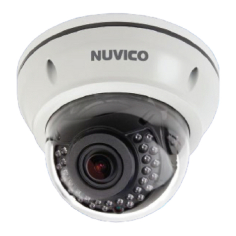
starlight COAX SNAPIT User manual

User’s ManualVer. 06/22
Before installing and using the camera, please read this manual carefully.
Be sure to keep it handy for future reference.
STAR-LIGHT 8QLYHUVDO+'
RYHU&RD[TM6QDSLW702XWGRRU
'RPH CameraV
':&9:'
':&9:7,5
5

CAUTION
RISK OF ELECTRIC SHOCK.
DO NOT OPEN
This symbol indicates that dangerous voltage
consisting a risk of electric shock is present within
this unit.
This exclamation point symbol is intended to alert the
user to the presence of important operating and
maintenance (servicing) instructions in the literature
accompanying the appliance
1. In the use of the product, you must be strict compliance with the electrical safety regulations of
the nation and region. When the product is mounted on a wall or ceiling, the device shall be
firmly fixed.
2. Be sure to use only the standard adapter specified in the specification sheet. Using any other
adapter could cause fire, electrical shock, or damage to the product.
3. Make sure the power supply voltage is correct before using the camera.
4. Incorrectly connecting the power supply or replacing the battery may cause an explosion, fire,
electric shock, or damage to the product.
5. Do not connect multiple cameras to a single adapter. Exceeding the capacity may cause
excessive heat generation or fire.
6. Securely plug the power cord into the power source. An insecure connection may cause a fire.
7. When installing the camera, fasten it securely and firmly. A falling camera may cause personal
injury.
8. Do not install in a location subject to elevated temperature, low temperature, or high humidity.
Doing so may cause fire or electric shock.
9. Do not place conductive objects (e.g. screwdrivers, coins, metal items, etc.) or containers filled
with water on top of the camera. Doing so may cause personal injury due to fire, electric shock,
or falling objects.
10. Do not install the unit in humid, dusty, or sooty locations. Doing so may cause fire or electric
shock.
TO REDUCE THE RISK OF ELECTRIC SHOCK, DO NOT REMOVE COVER (OR BACK) NO USER
SERVICEABLE PARTS INSIDE. REFER SERVICING TO QUALIFIED SERVICE PERSONNEL.
CAUTION:
WARNING
Safety Information
2

11. Do not install near any heat sources such as radiators, heat registers, or other products
(including amplifiers) that produce heat.
12. Keep out of direct sunlight and heat radiation sources. It may cause a fire.
13. If any unusual smells or smoke come from the unit, stop using the product at once.
Immediately disconnect the power source and contact the service center. Continued use in
such a condition may cause fire or electric shock.
14. If this product does not operate normally, contact the nearest service center. Never
disassemble or change this product in any way.
15. When cleaning the product, do not spray water directly onto parts of the product. Doing
so may cause fire or electric shock.
1. Use proper safety gear when installing and wiring the product.
2. Do not drop objects on the product or apply strong shock to it. Keep away from a location
subject to excessive vibration or magnetic interference.
3. Do not use this product near water.
4. The product shall not be exposed to dripping or splashing and no objects filled with liquids,
such as vases, shall be placed on the product.
5. Avoid aiming the camera directly towards extremely bright objects such as the sun, as this
may damage the image sensor.
6. The Main plug is used as a disconnect device and shall stay readily operable at any time.
7. Remove the power adapter from the outlet when then there is lightning. Neglecting to do
so may cause fire or damage to the product.
8. Do not block any ventilation openings. Install following the manufacturer’s instructions.
9. A polarized or grounding-type plug is recommended for this product. A polarized plug has
two blades with one wider than the other. A grounding-type plug has two blades and a
third grounding prong. If the provided plug does not fit into your outlet, consult an
electrician for replacement.
CAUTION
Safety Information
3

10. Protect the power cord from being walked on or pinched particularly at plugs, convenience
receptacles, and the point where they exit from the product.
11. If any laser equipment is used near the product, make sure the surface of the sensor is not
exposed to the laser beam as that may damage the sensor module.
12. If you want to move the already installed product, be sure to turn off the power and then move or
reinstall it.
13. Proper configuration of all passwords and other security settings is the responsibility of the
installer and/or end-user.
14. If cleaning is necessary, please use a clean cloth to wipe it gently. If the device will not be used for
a long time, please cover the lens cap to protect the device from dirt.
15. Do not touch the camera’s lens or sensor module with fingers. If cleaning is
necessary, please use a clean cloth to wipe it gently. If the device will not be
used for a long time, please cover the lens cap to protect the device from dirt.
16. Use only attachments/accessories specified by the manufacturer.
17. Always use hardware (e.g. screws, anchors, bolts, locking nuts, etc.) compatible with the
mounting surface and of sufficient length and construction to ensure a secure mount.
18. Use only with cart, stand, tripod, bracket, or table specified by the manufacturer, or sold
with the product.
19. Unplug this product when a cart is used. Use caution when moving the cart/product combination
to avoid injury from tip-over.
20. Refer all servicing to qualified service personnel. Servicing is needed when the product has been
damaged in any way, such as power supply cord or plug is damaged, liquid has been spilled or
objects have fallen into the product, the product has been exposed to rain or moisture, does not
operate normally, or has been dropped.
Legal considerations
Video surveillance can be regulated by laws that vary from country to country. Check the laws in your
local region before using this product for surveillance purposes.
Contents
Important Safety Instructions
4

Important Safety Instructions
Liability
Every care has been taken in the preparation of this document. Digital Watchdog cannot be held responsible
for any technical or typographical errors and reserves the right to make changes to the product and manuals
without notice.
Digital Watchdog makes no warranty of any kind regarding the material contained within this document.
Digital Watchdog shall not be liable nor responsible for incidental or consequential damages in connection
with the furnishing, performance, or use of this material. This product is only to be used for its intended
purpose.
Equipment modifications
This equipment must be installed and used in strict accordance with the instructions given in the user
documentation. Changes or modifications not expressly approved by the party responsible for compliance
could void the user’s authority to use the equipment.
Trademark acknowledgments
Digital Watchdog, DW, DW Spectrum, MEGApix and Star-Light are registered trademarks or trademark
applications of Digital Watchdog in various jurisdictions.
Apple, Apache, Bonjour, Chrome, Ethernet, Internet Explorer, Linux, Microsoft, Mozilla, Real, SMPTE,
QuickTime, UNIX, Windows, and WWW are registered trademarks of the respective holders. Java and all Java-
based trademarks and logos are trademarks or registered trademarks of Oracle and/or its affiliates. The UPnP
Word Mark and UPnP Logo are trademarks of Open Connectivity Foundation, Inc. in the United States, or
other countries.
microSD, microSDHC, and microSDXC Logos are trademarks of SD-3C LLC. microSD, microSDHC, microSDXC
are trademarks or registered trademarks of SD-3C, LLC in the United States, other countries, or both.
Safety
This product is intended to be supplied by a UL Listed Power Supply Unit marked “Class 2” or “LPS” or “PS2”
and rated 12 Vdc, 0.73A min. or 24 Vac, 50/60Hz 0.51A min (DWC-V4283WTIR) and rated 12 Vdc, 0.53A min.
or 24 Vac, 50/60Hz 0.36A min (DWC-V4283WD).
5

Regulatory Information
USA
This device complies with part 15 of the FCC Rules, subject to the following two conditions: (1) this device
may not cause harmful interference, and (2) this device must accept any interference received, including
interference that may cause undesired operation.
This equipment has been tested and found to comply with the limits for a Class B digital device, according to
part 15 of the FCC Rules. These limits are designed to provide reasonable protection against harmful
interference in a residential installation. This equipment generates, uses and can radiate radio frequency
energy and, if not installed and used following the instructions, may cause harmful interference to radio
communications. However, there is no guarantee that interference will not occur in a particular installation. If
this equipment does cause harmful interference to radio or television reception, which can be determined by
turning the equipment off and on, the user is encouraged to try to correct the interference by one or more of
the following measures:
• Reorient or relocate the receiving antenna.
• Increase the separation between the equipment and receiver.
• Connect the equipment into an outlet on a circuit different from that to which the receiver is connected.
• Consult the dealer or an experienced radio/TV technician for help
Canada
This digital apparatus complies with CAN ICES-3 (Class B). The product shall be connected using a shielded
network cable (STP) that is properly grounded. Cet appareil numérique est conforme à la norme CAN NMB-3
(classe B). Le produit doit être connecté à l'aide d'un câble réseau blindé (STP) qui est correctement mis à la
terre.
Disposal and recycling
Digital Watchdog cares for the environment at all product manufacturing stages and is taking measures to
provide customers with more environmentally friendly products. When this product has reached the end of
its useful life, dispose of it according to local laws and regulations. For information about your nearest
designated collection point, contact your local authority responsible for waste disposal. Following local
legislation, penalties may be applicable for incorrect disposal of this waste.
Copyright © Digital Watchdog 2022. All rights reserved. Specifications and pricing are subject to change
without notice.
Important Safety Instructions
6

Contents
INTRODUCTION
Features
Product & Accessories
PartsName
Dimension
08
09
10
11
INSTALLATION
Installa�on
Connec�ng to Monitors
Control Board
Adjus�ng the Camera angle
12
14
16
18
APPENDIX
Troubleshoo�ng
Specifications
32
33
7
OSD MENU
Menu Tree
Exposure
Color
Day/Night
Function
Motion
Privacy
Setup
Exit
19
20
24
25
26
27
28
29
31
36 LIMITS AND EXCLUSIONS
37 WARRANTY INFORMATION

Features
Universal HD over Coax® technology with HD-Analog, HD-TVI, HD-CVI and all legacy analog
signal support
Star-Light™ super low light technology
2.1MP/1080p 1/3" image sensor at real-time 30fps
2.8~12mm motorized zoom auto-focus p-iris lens
True wide dynamic range (WDR)
OSD control via coaxial (UTC)
Snapit™ easy installation housing
CleanView™ hydrophobic dome coating repels water, dust and grease
Cold Start -40°F (-40°C)
70' Smart IR™ with intelligent camera sync. (DWC-V4283WTIR model)
Smart DNR™ 3D digital noise reduction
True day/night mechanical IR cut filter (DWC-V4283WTIR model)
De-Fog™ extreme weather image compensation
Highlight masking exposure (HME)
Auto sensing 24VAC/12VDC with line lock
Easy icon driven OSD menu with built-in joystick
Programmable Privacy Zones
Auto gain control (AGC)
Backlight compensation (BLC)
Auto white balance (AWB)
UL listed
UTP and RS485 built-in
Junction box built-in
NDAA compliant
IP68 dust-tight and waterproof
IK 10-rated impact-resistant
5 year warranty
█
█
█
█
█
█
█
█
█
█
█
█
█
█
█
█
█
█
█
█
█
█
8
█
█
█
█
█

Camera Cables
DC Plug Cable
Manual Screw &
Template Sheet
Hexagonal Wrench
(for NPT Plug Set Screw) Torx Screw Driver Moisture absorber &
Absorber Guide
Product & Accessories
Please check if all the camera and accessories are included in the package.
9

Surface Mount Base
Flush Mount Base
Tilt Stopper Screw
Lens
Control Board
Dome Cover
Power Cable
CVBS Cable
Universal Cable
UTP, RS485, Alarm
NPT Plug
Partsname
UNIVERSAL DC12V
AC24V CVBS
UTP
BLUE +
DOT -
RS 485
ORG D+
DOT D -
ALARM
10

Unit: inches (mm)
ø5.47" ( ø139mm)
2.55" (65.0mm)
2.11" (53.8mm)
Dimension
11

Disassembling
1. Detach the dome cover using the star wrench drive.
Detach the body from surface mount bracket using a
Philips screwdriver.
2. placing
dome cover on to the bracket.
3.
Before installing your camera:
1. The mounting surface must withstand five times the camera weight.
2. Pay attention to the cables. The can easily become caught and damaged. Any damage
may cause a short or fire.
3. Install the moisture absorber in the base of the camera’s lens.
a. Remove the moisture absorber from the packaging.
b. Place the moisture absorber around the base of the camera’s lens module.
12
Please attach the card type absorber to
attachment point as the picture.
WARNING: It is highly recommended that you install the moisture
absorber when mounting the camera. The moisture
absorber prevents moisture from being captured
inside the camera's housing, which may cause image
performance issues and damage the camera.
NOTE: During operation. In most cases it will not need the
moisture absorber for more than the first day. In cases
where the camera can experience a moisture issue,
users must keep the moisture absorber in the camera.
The moisture absorber has an approximately 6-month
life cycle, varying depending on the environment.

2
3
4
5
6
7
Using the mounting template sheet or the camera
itself, mark and drill the necessary holes in the wall or
ceiling.
Athe junction box to the mounting surface using
the included anchors and screws.
Pass wires through and make all necessary connections.
Secure the camera module to the junction box by
aligning the three (3) screws on the camera module to
the respective holes in the junction box.
Adjust the camera’s pan, tilt and position to achieve
the desired view. See page 18.
Place the dome over the camera to complete the
installation. Secure the dome into position using the
star wrench driver included.
Remove the dome’s protective film. Softly wipe the
dome/lens cover with lens tissue or a microfiber cloth
with ethanol to remove any dust or smudges left from
the installation process.
Template sheet
2
3
4
5
6
7
13
1

UTP/Coax switch
UTPCOAX
Use the diagram below to connect to an Universal DVR or CRT Monitor properly.
Coax Video Output Mode (Default Mode)
NOTE :
When switching to UTP/Coax switch to Coax, the image will not be output when switched to UTP.
UNIVERSAL DVR
12VDC/24VAC
UNIVERSAL (COAX)
CVBS
14

UNIVERSAL DVR
UTP/Coax switch
UTPCOAX
Use the diagram below to connect to an Universal DVR or CRT Monitor properly.
UTP Video Output Mode
Balun
(Receiver at DVR side)
NOTE :
When switching to UTP/Coax switch to UTP, the image will not be output when switched to Coax.
12VDC/24VAC
UNIVERSAL (UTP)
CVBS
15

Image Mode
Control Board
CVBS(960H)
U
Enter R
L
D
HD-A
HD-TVI
HD-CVI
16

- RS485 Connectors : Connect the camera to a controller or the DVR using RS485
Orange : RS485 +, Orange + Dot : RS485 -
- UTP Cable : Connect when using UTP video output mode.
Blue : UTP +, Blue + Dot : UTP -
Yellow : Alarm , Blue : GND
Control Board
UTP
BLUE +
DOT -
RS 485
ORG D+
DOT D -
ALARM
17

°
Panning 360°
°
(Non-IR 75°)
18

WHITE BAL.
COLOR GAIN
EXIT JUMP
AUTO / AUTO-EX / PRESET
/ MANUAL
0 ~ 20
COLOR
EXPOSURE
LENS
BACKLIGHT
DRC
DEFOG
AGC
STARLIGHT
3D DNR
EXIT JUMP
MANUAL / AUTO
OFF / HME / BLC / WDR
OFF / LOW / MIDDLE / HIGH
OFF / ON
0 ~ 10
OFF / x2 ~ x32
OFF / LOW / MIDDLE / HIGH
&910
3(#
SHARPNESS
GAMMA
MIRROR
FLIP
EXIT JUMP
0 ~ 10
0.45 ~ 0.75
OFF / ON
OFF / ON
MODE
CDS THRES
CDS MARGIN
EXTERN SW
EXT LED
DELAY
SMART IR
EXIT JUMP
AUTO / COLOR / BW / EXTERN
0 ~ 20
0 ~ 20
LOW / HIGH
OFF/ AUTO
LOW / MIDDLE / HIGH
0 ~ 20
DAY & NIGHT
FUNCTION
%/
'6/$
OFF / RIGHT UP / LEFT DOWN
FULL / COMP / USER
50Hz / 60Hz
ENG/ CHN/ CHN(S)/ JPN / KOR
OFF / ON
COMMUNICA
CAM TITLE
IMAGE RANGE
FREQ
LANGUAGE
INITIAL
EXIT JUMP
OFF / ON
0 ~ 15
OFF / ON
0 ~ 59
0 ~ 33
0 ~ 60
0 ~ 34
0 ~ 20
0 ~ 20
0 ~ 20
0 ~ 3
PRIVACY
ZONE NUM
ZONE DISP
H-POS
V-POS
H-SIZE
V-SIZE
Y LEVEL
CB LEVEL
CR LEVEL
TRANS
EXIT JUMP
PRIVACY
SETUP
4&5
OFF / ON
0 ~ 4
OFF / ON
0 ~ 10
OFF / ON
OFF / ON
OFF / ON
MOTION
DET WINDOW
DET TONE
MDRECT FILL
SENSITIVITY
MOTION OSD
TEXT ALARM
SIGNAL OUT
EXIT JUMP
MOTION
.05*
13*7
SAVE & EXIT
EXIT
EXIT
The contents might be different some products.
&9*5
NOTE:The function setting can be adjusted with both switch (OSD joystick) and remote control through RS485 or UTC.
In case of camera without OSD joystick, it can be adjusted with coaxial (UTC) only.
19
OSD Menu Tree

1
LENS
MANUAL : Manual mode supports the fixed board lens or the manual iris lens.
AUTO : AUTO mode sets the camera’s iris automatically.
Under the LENS sub-menu, you can adjust the following settings:
1. Level
Change the camera’s iris value manually. If AUTO is selected, this option is disabled.
Set the shutter speed to AUTO, Manual, or FLC (Flicker-less mode).
* If AUTO is selected, select from the following options :
- NORMAL: Set when the camera is installed in an indoor environment.
- DEBLUR: Set when the camera is installed in an outdoor environment.
* Select FLC if the camera is experiencing some flickering in the image.
The shutter speed will be set to 1/100 for NTSC, or 1/120 for PAL.
* If Manual is selected, set the shutter speed from the options :
- 1/30(1/25) ~ 1/30000.
LENS AUTO
BACKLIGHT OFF
DRC OFF
DEFOG OFF
AGC 10
STARLIGHT X4
3D DNR HIGH
EXIT JUMP
EXPOSURE
&910 .05* 13*73(# %/ '6/$ 4&5 &9*5
2. Brightness
Adjust the camera’s brightness from 0~20. The higher the number, the brighter the image will appear.
3. Shutter
1
LENS
LEVEL 20
BRIGHTNESS 10
SHUTTER AUTO
2-MOTOR
RETURN
20
OSD Menu_Exposure
This manual suits for next models
2
Table of contents
