STARWELD QUATRO 450 User manual

QUATRO 450
OPERATOR’S MANUAL
IMPORTANT
DO NOT INSTALL, OPERATE OR
REPAIR THIS EQUIPMENT
WITHOUT READING THIS MANUAL
AND THE SAFETY SECTION
CONTAINED INSIDE THIS MANUAL
STARWELD WELDING SOLUTIONS
WEBSITE: www.starweld.co.za TEL: +27 11 914 4696
FAX: +27 11 914 3224

Starweld Quatro 450 Operator’s Manual
2
1 Table of Contents
1Table of Contents .............................................................................................2
2Safety.................................................................................................................3
3Installation.........................................................................................................6
3.1 SPECIFICATIONS........................................................................................................6
3.2 DUTY CYCLE .............................................................................................................6
3.3 SELECTING LOCATION ..............................................................................................6
3.4 WELD CABLE SIZES..................................................................................................8
3.5 STICK WELD CONNECTION.......................................................................................8
3.6 MIGWELD CONNECTION .........................................................................................8
3.7 TIGWELD CONNECTION ..........................................................................................8
3.8 CONNECTING INPUT POWER.....................................................................................9
4Operation.........................................................................................................10
4.1 CONNECTIONS.........................................................................................................11
4.1.1 Power.................................................................................................................11
4.1.2 Output Terminals..............................................................................................12
4.1.3 14-way Socket..................................................................................................12
4.2 LIFT TIG..................................................................................................................12
5Advanced Features.........................................................................................13
5.1 VOLT-LOC ...............................................................................................................13
6Maintenance and Troubleshooting ...............................................................14
6.1 ROUTINE MAINTENANCE.........................................................................................14
6.2 TROUBLESHOOTING ................................................................................................14
7Electrical Diagrams ........................................................................................15
8Parts.................................................................................................................16
9Warranty..........................................................................................................18

Starweld Quatro 450 Operator’s Manual
3
2 Safety
Only qualified persons should install, operate, maintain, and repair this unit.
During operation, keep everybody, especially children, away.
Electrical Hazards
Electric shock from welding can kill or cause severe burns. The electrode and work
circuit is electrically energized whenever the output is on. The input power circuit
and unit internal circuits are also electrically energized when the mains power is on.
When MIG welding, the wire, drive rolls, and all other metal parts touching the wire
are electrically energized. Incorrectly installed or improperly grounded equipment
presents a shock hazard.
Read the instruction manual before installing, operating, or servicing the unit.
Have all installation, operation, maintenance, and repair work performed only
by qualified people.
Do not touch live electrical parts.
Wear dry, insulating in good condition and protective clothing.
Insulate yourself from the workpiece and ground by wearing rubber-soled
shoes or standing on a dry insulated mat or platform.
Use fully insulated electrode holders. Never dip the holder in water to cool it
or lay it on conductive surfaces or the work surface. Do not touch holders
connected to two welding machines at the same time or touch other people
with the holder or electrode.
Do not use worn, damaged, undersized, or poorly spliced cables, welding gun
cables, and torch cables. Make sure all connections are tight, clean, and dry.
Do not wrap cables carrying welding current around your body.
In confined spaces or in electrically hazardous locations due to water or
perspiration, do not use a welder with AC output unless it is equipped with a
voltage reducer and remote output control. Use equipment with DC output.
Turn off all equipment when not in use. Disconnect the power to equipment if
it will be left unattended or out of service.
Wear a safety harness to prevent falling in a potentially hazardous area.
Keep all covers secured in place.
Many welding processes produce fumes and gases, which may be harmful to your
health.
Keep your head out of the fumes. Do not breathe the fumes.
If inside, use ventilation or an exhaust at the arc to remove welding fumes
and gases.
Welding Fumes and Gases
Starweld Quatro 450 Operator’s Manual
4
If ventilation is poor, use an approved respirator.
Do not weld near degreasing, cleaning or spraying booths. The heat and rays
from the arc can react with the gases from those processes to form toxic
fumes.
Do not weld on coated metals, such as galvanized, lead or cadmium plated
steel, unless the coating is removed. The coatings can give off toxic fumes if
welded.
Arc rays from the welding process produce intense rays that can burn skin and
eyes.
Wear a welding helmet fitted with correct shade of filter lens when welding in
order to protect eyes and face.
Use protective screens or barriers to protect passer-bys, warn others not to
watch the arc.
Wear protective clothing made from durable and flame-resistant material as
well as foot protection.
Protect exposed skin on hands with leather gloves.
Welding processes produce molten metal, sparks and hot work surfaces. These can
cause fire or explosion if precautionary measures are not followed. Welding on
closed containers can them to explode. Check and make sure the work area is safe
before doing any welding.
Remove any combustible material from the work area.
Remove or make safe all combustible materials for a radius of 10m around
the work area. If this is not possible then cover materials with approved
flame-resistant covers.
Do not weld where sparks can strike combustible material.
Do not weld on a container that has held an unknown substance or a
combustible material whose contents, when heated, can produce flammable
or explosive fumes.
Do not weld on a workpiece covered by an unknown substance or whose
coating can produce flammable, toxic, or reactive fumes when heated.
Do not use welder to thaw frozen pipes.
Do not weld on closed containers such as drums unless they are correctly
prepared.
Always keep a fire extinguisher close by.
Arc Rays
Fire and Explosion
Hot Surfaces / Flying Metal / Noise

Starweld Quatro 450 Operator’s Manual
5
Do not touch hot parts without gloves.
Allow cooling period before working on a gun or torch.
Welding, grinding and chipping can cause sparks and flying metal.
Wear approved safety glasses with side shields even under the welding
helmet.
Wear approved ear protection if noise level is too high.
Electric arc welding processes produce intense electric and magnetic fields.
Persons with a pacemaker should not go near welding operations until they have
consulted their doctor and obtained information from the manufacturer of the device.
Pacemakers

Starweld Quatro 450 Operator’s Manual
6
3 Installation
3.1 Specifications
Input
Input Voltages
Maximum Input Current
380V
43A
Rated Output
Duty Cycle
Output Amperes
Volts at Rated
Output Amperes
Input Amperes
380V
Stick 100%
450A
38V
43A
TIG 100%
450A
28V
32A
MIG 100%
450A
37.5V
43A
Output
Output Current Range
Open Circuit Voltage
Type of Output
15-450A
55V
DC
Physical Dimensions
Height
Width
Depth
Weight
370mm
350mm
500mm
33kg
Environmental
Operating
Temperature
Range
Storage
Temperature
Range
Relative Humidity
Altitude Above
Sea Level
-10C to +40C
-50C to +80C
Up to 50% at 40C
Up to 90% at 20C
Up to 1800m
3.2 Duty Cycle
Duty cycle is the percentage of ten minutes that the unit can weld at selected current
without overheating.
If the unit was used at 450A (Maximum Current) then the unit could weld
continuously, that is no time is needed in order to let the unit cool.
3.3 Selecting Location
The air is blown from the rear of the unit through the heatsink and out the front of the
unit, therefore adequate thought needs to be considered about the location of the
unit.
The unit should be spaced at least 15cm away from a wall at the rear of the
machine, this will allow adequate airflow into the unit.

Starweld Quatro 450 Operator’s Manual
7
15cm
Unit
Wall
Front of
Unit
Figure 1: Location of Unit
Starweld Quatro 450 Operator’s Manual
8
3.4 Weld Cable Sizes
Turn off power before connecting to unit output terminals
Do not use worn, damaged, and undersized cables
Minimum welder cable size (mm2)
Welding
Amperes (A)
20
40
60
80
100
Total
Cable
Length
(m)
50
16
16
16
25
25
100
16
25
35
50
50
150
16
35
50
70
70
200
25
35
70
95
95
250
35
50
70
95
120
300
35
70
95
95
120
350
50
70
95
120
120
400
50
70
95
120
120
Figure 2: Cable Area vs. Cable Length
This chart serves only as a general guide, if the unit tends to trip early on overtemp
or the cables become warm then the next size cable should be used.
If one wants to weld at 150A 60% duty cycle with the total cable length, that is earth
cable and electrode cable, of 100m then the cable size should be 70mm2.
3.5 Stick Weld Connection
Stick welding requires positive polarity, that is the electrode holder is connected to
the unit’s positive output socket (red connector) and the earth clamp is connected to
the unit’s negative output socket (black connector).
3.6 MIG Weld Connection
MIG welding requires positive polarity, that is the earth clamp is connected to the
unit’s negative output socket, the separate wire feeder unit is connected to the
positive terminal through an interconnecting cable, the wire feeder control cable also
needs to be connected to the female 14 way socket.
3.7 TIG Weld Connection
TIG welding requires negative polarity, that is the electrode holder is connected to
the unit’s negative output socket and the earth clamp is connected to the unit’s
positive output socket.
Starweld Quatro 450 Operator’s Manual
9
The Starweld Quatro 450 does not include a gas solenoid inside the unit, therefore a
TIG torch needs to be used with a gas valve built into it. The gas line from the torch
is then connected straight to the flowmeter on the gas cylinder.
3.8 Connecting Input Power
Turn off power before connecting unit to mains
Do not use worn, damaged, and undersized cables or plugs
The unit is supplied with usually a five meter trailing cable (other lengths are
available on request). If no plug is supplied with the unit then the connections are
the following:
Green/Yellow - Represents the earth wire
Brown - Represents Phase A
Blue - Represents Phase B
Black - Represents Phase C
The Quatro 450 is designed to work on a three phase with earth system only.
Starweld Quatro 450 Operator’s Manual
10
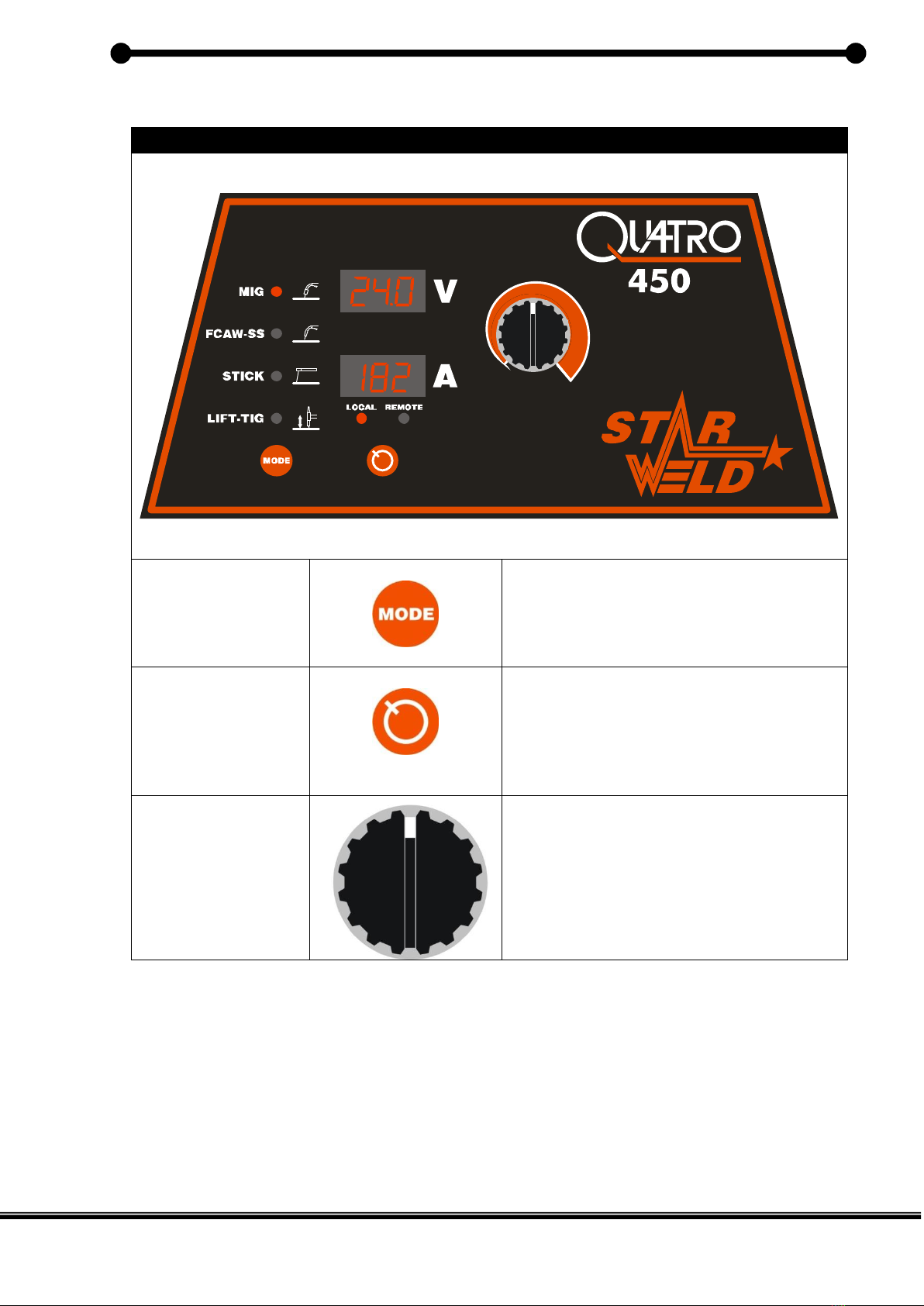
4 Operation
CONTROL PANEL
MODE
BUTTON
This button is used when selecting the
Welding Process to be used. With each
press of the button, one scrolls down
through the modes. An accompanying
LED indicates the selected mode.
LOCAL/REMOTE
BUTTON
Used to select the input reference.
Either from the main encoder (local) or
from a suitable remote controlling
device. When in the TIG and Stick
modes the remote device will control
from 0 –local setting.
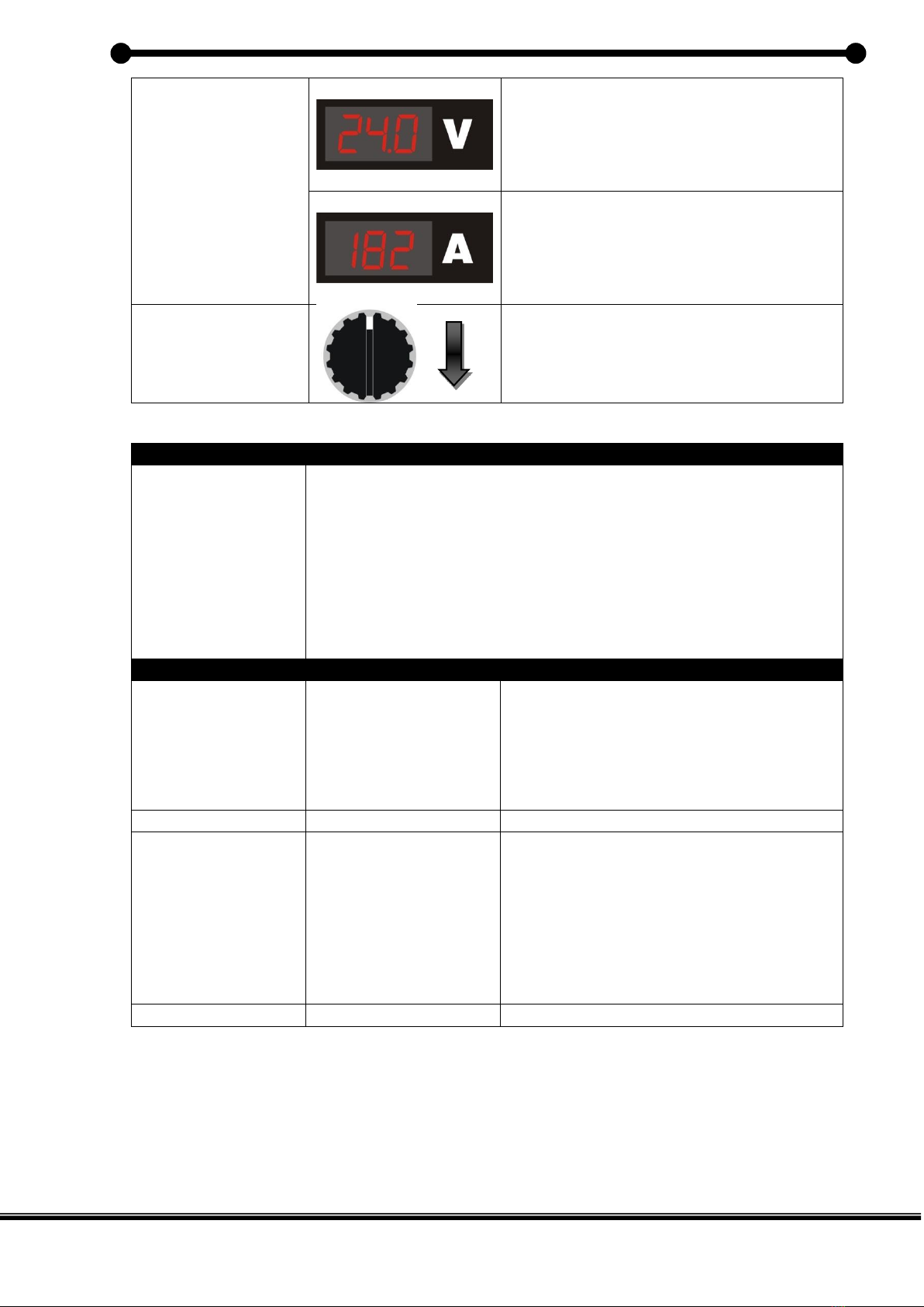
ENCODER
This control is used to select the
required Amperage or Voltage to be
used. The Encoder is also used to set
values in Menu Settings. (To be
discussed later)
Starweld Quatro 450 Operator’s Manual
11
DIGITAL
DISPLAYS
In the MIG mode the preset welding
voltage is displayed before welding
commences, once welding the actual
voltage is displayed. All other modes
displays the actual voltage.
Before welding the preset welding
current is displayed, once welding the
actual current is displayed.
MENU
BUTTON
This button allows for the setting of the
various welding parameters, subject to
the selected mode.
MENU OPERATION
METHOD
1. Push the Menu Button twice.
2. Use the Encoder to select the parameter to be set. (This
will appear on the Voltage Display)
3. Push the Menu Button a second time.
4. The parameter in the Voltage Display will begin to flash,
indicating that this has been selected for change.
5. Use the Encoder to now adjust this parameter.
6. After the desired value is selected, press the Menu
Button again, to exit.
PARAMETERS OPTIONS
MIG Process
SLOPE
Setting: 1 –10
This is an inductance control that sets
the speed at which the current picks
up, after each short of the arc. A high
setting is recommended for Aluminium
and a low setting for Steels.
FCAW-SS
Nothing
Stick Process
DIG
Setting: 1 –10
Controls the amount of added current
during the deposition of welding
material to prevent freezing of the
puddle.
The higher the setting, the greater the
added current.
Lift TIG Process
Nothing
4.1 Connections
4.1.1 Power
The circuit breaker at the rear of the unit switches the unit on and off.
Starweld Quatro 450 Operator’s Manual
12
4.1.2 Output Terminals
Turn off power before connecting cables to unit
One can get shocked by the output terminals if correct care is
not exercised
Unit’s Positive Terminal, normally a red feed through connector, however if the unit
has been built using Dinse connectors then the terminal is marked as such:
Unit’s Negative Terminal, normally a black feed through connector, however if the
unit has been built using Dinse connectors then the terminal is marked as such:
4.1.3 14-way Socket
The 14 way socket is used for the connection of torch triggers, interconnection
cables and ancillary equipment
Pin
Function
1
TIG Trigger
2
TIG Trigger
3
Pot GND
4
Pot Wiper
5
Pot +5V
6
CAN Bus H
7
CAN Bus L
8
9
10
+24VAC Neutral
11
+24VAC Live
12
Trigger Return (11 to 12)
13
14
4.2 Lift TIG
The tungsten must be placed, not scratched on the work and the inverter will supply
a preset low current of approximately 100 amps after 100ms. On lifting the tungsten
the current will rise to the preset value. In order to break the arc simply pull the torch
away from the workpiece
NB It is important to remember for TIG welding the electrode is connected to the
negative and the earth clamp to the positive.
+
-

Starweld Quatro 450 Operator’s Manual
13
5 Advanced Features
5.1 Volt-Loc
Volt-Loc is the registered name of the Starweld voltage reducer.
Volt-Loc is a free option and is generally fitted as standard. It is used for the stick
and TIG modes. The Volt-Loc feature reduces the output voltage to 13 volts until
contact resistance below approximately 200 Ohms is made. On contact the full open
circuit voltage is applied and welding may continue as long as there is welding
current and after an internally set time for tacking. Thereafter the voltage is once
more reduced.
The time that is allowed for tacking is set to 2s.
The use of Volt-Loc provides considerable protection against electrocution.
Accidents occur when the equipment is improperly used or maintained and the rules
of safe practice for electric arc welding must be observed. Failure to observe these
practices may cause serious injury of death.
Starweld will not be liable for any claims for injury or death or consequential
damage.
Starweld Quatro 450 Operator’s Manual
14
6 Maintenance and Troubleshooting
6.1 Routine Maintenance
Turn off power before undergoing maintenance on the unit
The unit should be blown out every 6 months to remove dirt and dust build up,
depending on site conditions. Worn or damaged machine sockets should be
replaced. Damaged mains cable should be replaced.
If the unit is used in a dusty environment then the unit should be blown out every 3
months.
In order to blow out the machine the cover should be removed and the dust blown
out with compressed air. An air pressure of 5 bar will be sufficient to remove any
dust buildup. It is important to get all the dust out the heatsink and fan as well.
6.2 Troubleshooting
Fault
Remedy
Power LED does not light
Switch the circuit breaker at the rear of the unit to the
on position.
Switch the unit on at the wall plug.
Make sure the wall plug is correctly wired.
Power LED on but no weld
output
Make sure the unit is switched to the stick position.
Check for Overtemp error (Err Ot)
Make sure unit is in the local mode and not remote.
Erratic or improper weld
output
Use proper size and type of weld cable.
Clean and tighten all weld connections including the
earth connection to the work.
Fan not working
Look for something blocking the fan.
Send the unit in for service to replace the fan.
Wandering arc
Use proper size tungsten.
Use properly prepared tungsten.
Reduce gas flow rate.
Unit not MIG welding
Check interconnecting cable for any bad connections
especially in 14 way socket
Check 10A circuit breaker on front panel

Starweld Quatro 450 Operator’s Manual
15
7 Electrical Diagrams
Starweld Quatro 450 Operator’s Manual
16
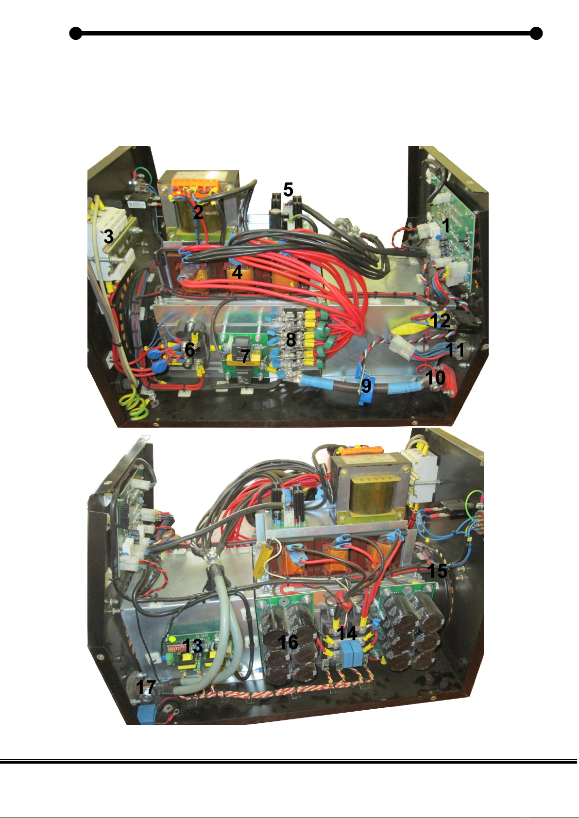
8 Parts

Starweld Quatro 450 Operator’s Manual
17
Parts List
1
WM000 Control Board
2
200VA Transformer
3
Circuit Breaker
4
HF Transformers
5
WM020 Power Board
6
Input Bridge
7
WM081 Soft Start
8
Output Diodes
9
LEM Module
10
Positive Socket
11
14 Way Socket
12
10A Circuit Breaker
13
WM010 Firing Board
14
IGBTs
15
Fan
16
WM080 Capacitor
Board
17
Negative Socket

Starweld Quatro 450 Operator’s Manual
18
9 Warranty
Arc Quip guarantees the product for a period of 24 months (2 years) from date of
sale against faulty design material and workmanship, fair wear and tear excepted
and excluding misuse and abuse.
The equipment must be returned to Arc Quip or its agents.
For service repairs and technical assistance contact your STARWELD dealer or the
manufacturer.
Distributor
Starweld Contact Details
Arc Quip cc
Unit 70D Van Dyk Secure Business Park
Cnr Van Dyk & Brakpan rd
Boksburg
South Africa
Po Box 1681
Fourways
2055
Tel: +27 11 914 4696
Technical: robert@starweld.co.za
Table of contents
Other STARWELD Welding System manuals

Popular Welding System manuals by other brands

Hobart Welders
Hobart Welders Handler 125 owner's manual

Lincoln Electric
Lincoln Electric statiflex 200-m Operator's manual

BOC
BOC Smootharc MMA 170 operating manual

Lincoln Electric
Lincoln Electric Fast Mate Guns Series Operator's manual

ESAB
ESAB Aristo Origo Feed 3004 instruction manual

STAMOS
STAMOS S-MAG 120 FL user manual

Miller
Miller GW-55C owner's manual

Lincoln Electric
Lincoln Electric Idealarc DC-600 Technical specifications

ESAB
ESAB Miggytrac 1001 instruction manual

BOSITE
BOSITE 5001A user manual

Shindaiwa
Shindaiwa EGW165M-I/UKV Owner's and operator's manual

MOSA Weld
MOSA Weld CT 230 YSX CC/CV Use and maintenance manual


