STARWELD TIGFIL User manual
1
TIGFIL

2

3
CONTENTS
Introduction 2
Features 3
Installation 4
Spareparts 6
Optional 12
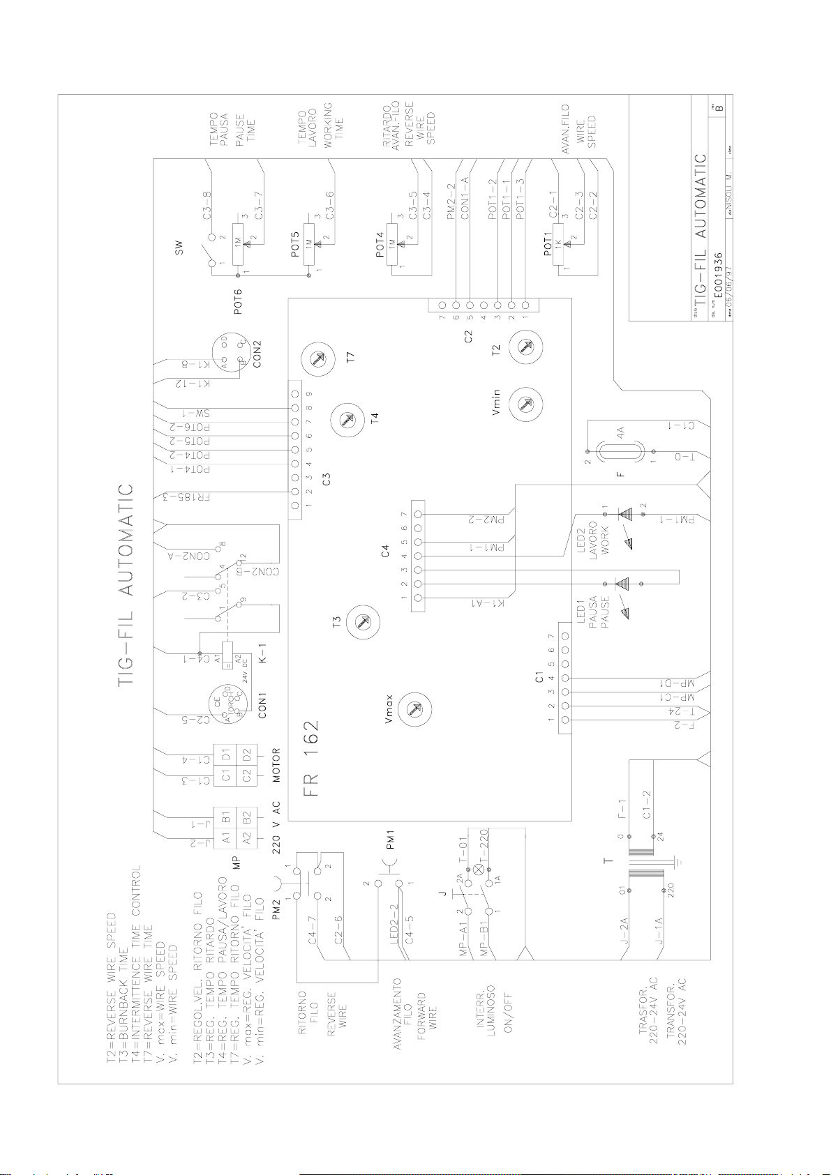
Electricdiagram 14

4
We kindly thank You for the confidence You showed in
purchasing one of our products.
We are sure we will not disappoint Your expectations; we
ask You to read the instructions shown in this manual
very carefully.
WARNING
GENERAL
This welding equipment has been designed, manufactured and tested to the
highestqualitystandardstoensurelongandtroublefreelife.However,regular
maintenanceisanessentialpartofkeepingthemachineoperatinginareliable
and safe manner and Your attention is drawn to any maintenance instructions
that are contained in this manual. In general, all welding equipment should be
thoroughly inspected, tested and serviced at least annually. More frequent
checking will be required when the equipment is heavly used. Wear and tear,
particularly in electro-mechanical and moving components, is a gradual
process. Caught in time, repair costs are small and benefits in performance,
reliabilityandsafetyaresignificant.Leftalone,theycanputtheequipment,and
You, at risk.
Thiswirefeederhasbeendesignedtofeedcoldwirewith TIGprocess.When
thetorchbuttonispressed,afteranadjustabledelay-time,thewirestartscoming
out with the preset feeding speed. The wire feeding can be continuous or
intermittent.Incaseofintermittentfeeding,thefeedingandpausetimemustbe
set.When weldingisoverandthetorchbuttonisreleased,thewireisretracted
so that it does not stick to the welding bath.
5
5
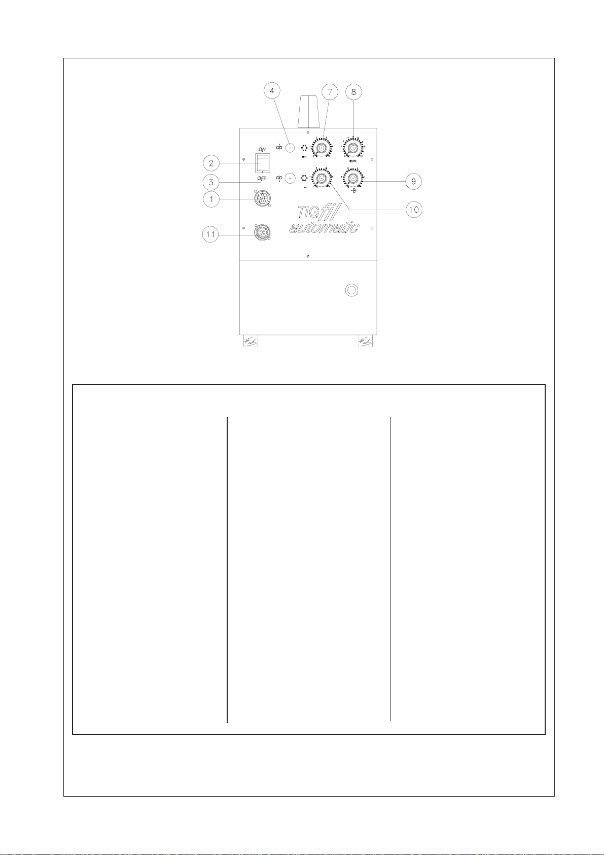
Working Time
Activation Indicator
6
Pause Time
Activation Indicator
7
Pause Time
Adjustsmotorpausetime
8
Delayed Start
Adjuststhewirestart
delayed
9
Wire Speed
Adjustment
Providescontinuous
adjustment of wire speed
from0 to 5 m/min
10
Working Time
11
Connector
Connectorto power source
CONTROLS
1
Main Connector
Connector for torch
2
On/Off Switch
3
Wire Return Button
4
Wire Inching Button
6
INSTALLATION
INITIALSETUP
2. Connections
Mount a socket on the
1. Feed Rolls
Before connecting the
electrical and gas
supplies, ensure that
the equipment is set
forthetypeandsizeof
wiretobeused.Check
that the stamped on
thefeedrollisthesame
of the diameter of the
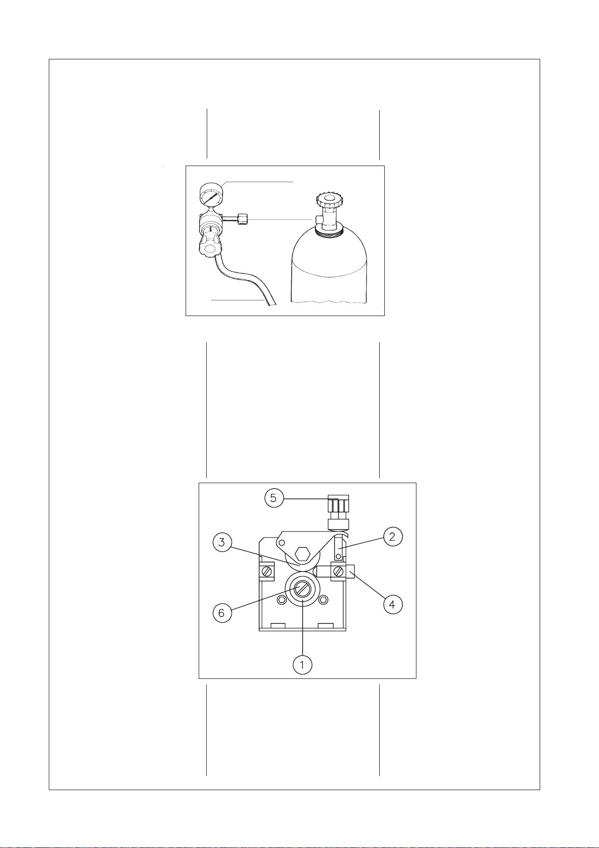
wireused. GASTUBE
PRESSUREREDUCER
HUBASSEMBLYMOUNTING on ball bearings and lift it.
Threadthewirethroughthe
fitting inlet guide (4) and
feed it out of the central
adaptor.
6-Lower the pressure roll
(3), refit it into the
initialpositionbythe
lever (2), adjusting
thepressurewiththe
knob.
Minimumpressureis
sufficientsoasnotto
allow the feeding
rolls to slip.
Excessive pressure
will cause wire
deformations and
entanglements
insidetheliner (incasealu
wires ) and generally early
wear-and-tear of the wire
feeding motor bushings. A
scanty pressure will cause
weldingunevennesses.
4- Adjust the hub assembly
by using the screw inside the
hubassemblywireguide,so
as to prevent the wire reel
over-run (and subsequent
wire entanglements), once
the motor of the wire feeder
stops.
Do not tighten the hub
assemblytoomuch:toomuch
pressurewillcauseexcessive
drag.
5-Bythefittingleverrelease
thepressureroll(3)revolving
1- Remove the hand (hub)
nut from the hub assembly
wire guide.
2-Placethewirereelonthe
hub so that the wire will be
drawn off from the top.
Ensurethatthewirespool
locates correctly on the
small pin on the flange of
thehubassemblywiregui-
de. Refit the hub nut.
3-Releasetheendofthe
wire , but do not allow the
wire to loosen. Cut off the
kinked portion of the wire
removing any
deformations.Thismustbe
doneeverytimethewireis
refedthroughtheequipment.
connection cable equipped
by the factory and with the
machine switched off,
connect it to the mains
supply.
3. Gas
Beforestartinganyprocess,
slowly open the gas bottle
andcheckifthegasquantity
suppliedcorrespondstothe
workneeds.

7
FEEDROLLREPLACEMENT
The feeding roll bears on its
visible side the diameter of
the wire which can be fed.
Shouldthisdiameternotwant
to use, untighten the screw
(6)blocking thefeedroll and
turn it or replace it.
Every roll is provided with
two grooves fitted for the
feedingofwireswithdifferent
diameters.
Special feed rolls are
available for flux cored and
alu wires.
TECHNICAL DATA
Imput voltage 50/60Hz V230
Wire diameter mm 0,6/1,2
Delayed Start sec 0,5/10
Stitching time sec 0,5/5
Pausetime sec 0,5/5
Max wire speed m/min 5
Absorbed power VA 60
Protection class IP 21
Dimensions LxPxH210x580x450
Weight Kg 19,5
8
OFF
ON
TIG
START

9
ATTENTION!! STARWELD20010reservestheright toaltercharacteristicatany time
withoutnotice.
STARWELD2010assumes no liability for results of a wrongapplication
oftheproductswhichmaycausedamagetopersonsorequipement.
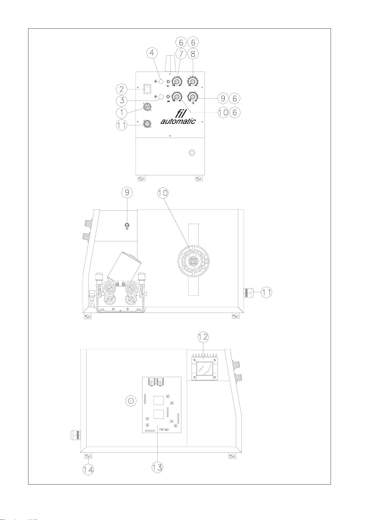
POS. Q.TY DESCRIPTION PARTNO.
1 1 5 poles female connector 000000625
2 1 Light on/off switch 000001856
3 1 Reversebutton 000002901
4 1 Button 000002897
5 1 1MPotentiometer+switch 000002883
6 1 Knob 000002227
7 1 1MPotentiometer 000060048
8 1 1KPotentiometer 000002870
9 1 Fuseholder 000002864
10 1 Hubassemblycomplete 000001237
11 1 Nut for cable 000000112
12 1 Auxiliarytransformer 000003688
13 1 PCBFR162 000003440
14 1 Rubberfeet 000000112
15 1 4 poles female connector 000000562
10
21
20
19
18 18
17
16
15
11
12
10
8
7
6
9
14
13
5
4
3
2
1
22
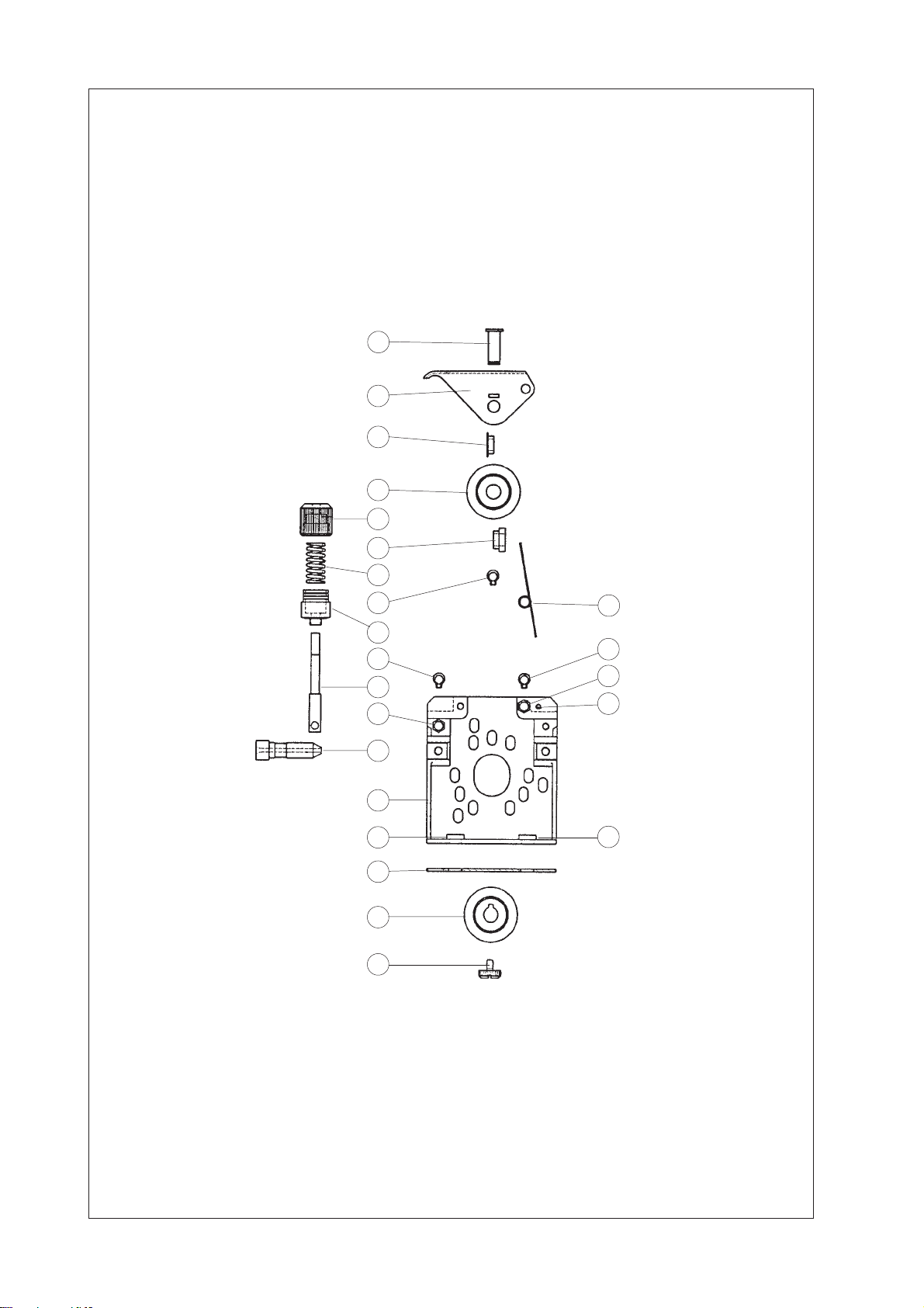
FEEDPLATETYPE4020-37

11
POS. Q.TY DESCRIPTION PARTNO.
1 1 Axle 000005107
2 1 Pressurearm 000005106
3 1 Spacernarrow 000000859
4 1 Pressureroll(37x12) 000002725
5 1 Fineadjustment 000005124
6 1 Spacerlarge 000020040
7 1 Spring 000005123
8 1 Clip 000005110
9 1 Spring left 000005126
10 1 Pressurebase 000005122
11 1 Axle 000005121
12 1 Clip 000005108
13 1 Axle 000005156
14 1 Pin 000005145
15 1 Axle 000005220
16 1 Inlet guide 000000254
17 1 Feedplate 000005150
18 2 Insulation 000002834
19 1 Insulationplate 000000205
20 1 Drive roll 0.6-0.8 000005239
20a 1 Drive roll 0.8-1.0 000005129
20b 1 Drive roll 1.0-1.2 000005136
20c 1 Drive roll 1.2-1.6 000005153
20d 1 Drive roll 1.2-1.6R 000005138
20e 1 Drive roll 1.0-1.2A 000005139
20f 1 Drive roll 1.2-1.6A 000005140
21 1 Screw 000004092
22 1 Clip 000005104
12

13
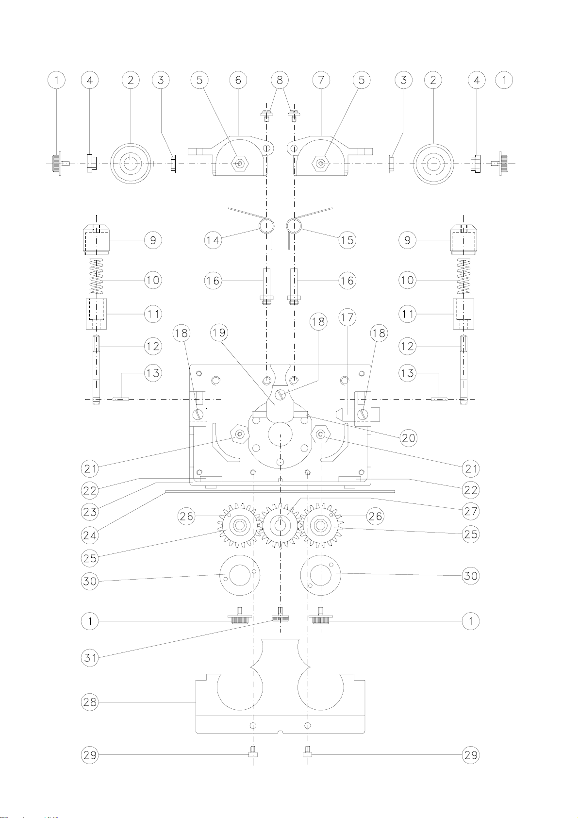
TYPE 1042
1 4 screw 000004092
2 2 Ball bearing 000002725
3 2 Spacernarrow 000000895
4 2 Spacerlarge 000020040
5 2 Axle 000100004
6 1 Pressurearmleft 000100005
7 1 Pressure arm right 000100007
8 1 Screw 000100006
9 1 Fineadjustment 000100008
10 2 Spring 000005123
11 2 Pressurebase 000100010
12 2 Axle 000100011
13 2 Axle 000100012
14 1 Spring 000100013
15 1 Spring 000100014
16 2 Axle 000100015
17 1 Inlet guide 000000254
18 3 Screw 000008545
19 1 Guide 000100022
20 1 Wire Guide 000100023
21 2 Axle 000100026
22 2 Insulation 000000027
23 1 Feed Plate 000100028
24 1 Insulation plate 000100030
25 2 Gear roll 000100002
26 2 Guide pin 000005119
27 2 Gear roll 000100029
28 2 Protection 001000031
29 2 Screw 001000032
30 2 DriveRoll 000005131
31 1 Screw 000004091
pos. piece Description part. NO.
14
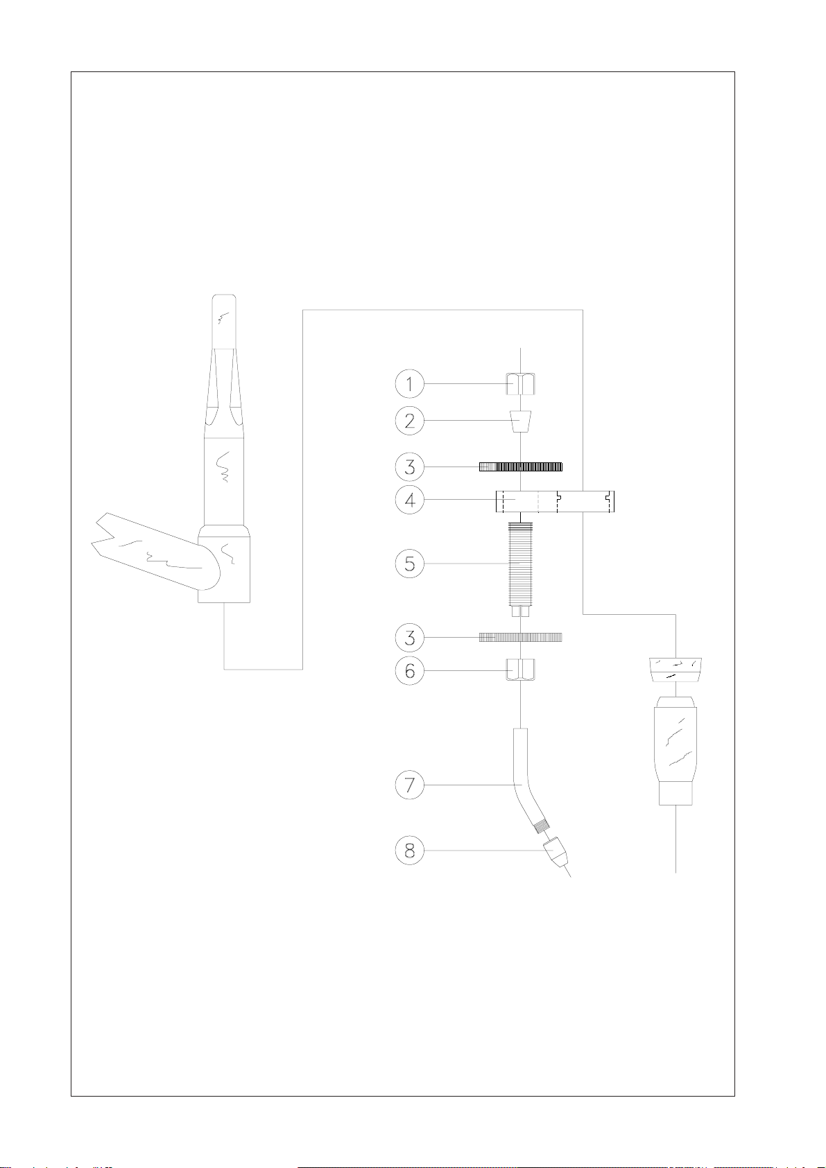
TIG-FIL TORCH KIT
(OPTIONAL )

15
POS. Q.TY DESCRIPTION CODE
1 1 linerstopscrew 000000336
2 1 Rubberconicalcap 000000175
3 1 Fixing ring 000000337
4 1 Support 000000338
5 1 Threadlever 000000339
6 1 Inletguidestopscrew 000000340
7 1 Inlet guide tube 000000341
8 1 Tip Ø 2 mm 000000342
TORCHKITPARTN°:000000355
ATTENTION!! STARWELD2010reservestherighttoalter characteristicat anytime
withoutnotice.
STARWELD2010assumes no liability for results of a wrongapplication
oftheproductswhichmaycausedamagetopersonsorequipement.
16

17
Model _ _ _ _ _ _ _ _ _ _ _ _ _ _ _ _ _ _ _ _ _
Serial N. _ _ _ _ _ _ _ _ _ _ _ _ _ _ _ _ _ _ _ _ _
Pageforcustomer'snotes
NOTES
Table of contents
Other STARWELD Welding System manuals

Popular Welding System manuals by other brands

Lincoln Electric
Lincoln Electric POWER WAVE 405 IM746 Operator's manual

REMS
REMS SSM 160 R operating instructions

ESAB
ESAB ET 300i instruction manual

Chicago Electric
Chicago Electric 58605 Owner's manual & safety instructions

Miller
Miller DYNASTY 350 owner's manual

Kemppi
Kemppi HiArc S 140 operating manual


