STATCON ENERGIAA HBD Series User manual
STATCON
Inspire Innovate Implement
ENERGIAA
PRODUCT MANUAL
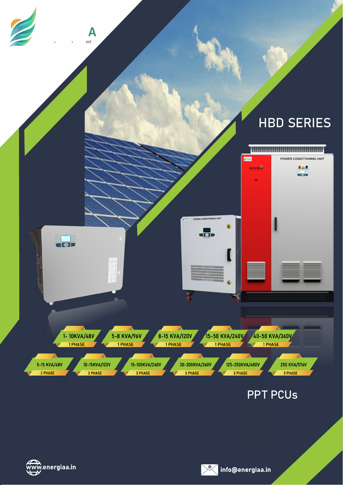
HBD SERIES
1P (1-50 KVA) & 3P (5-250 KVA) HYBRID MPPT PCUs
Genuine ‘Hybrid’ - Not just ‘Off-Grid’

1
Contents
Copyright Declaration ............................................................................................................................................... 2
1. NOTES ON THE MANUAL ....................................................................................................................................... 3
1.1 SCOPE OF VALIDITY .......................................................................................................................................... 3
1.2 TARGET AUDIENCE ......................................................................................................................................... 4
1.3 SYMBOLS USED ................................................................................................................................................ 4
2. INTRODUCTION ....................................................................................................................................... 5
2.1 PRODUCT DESCRIPTION ........................................................................................................................................................... 5
2.2 KEY ELEMENTS OF MACHINE ................................................................................................................................................ 6
2.2.1 MPPT-BASED SOLAR CHARGE CONTROLLER ............................................................................................................... 6
2.2.2 BIDIRECTIONAL INVERTER .................................................................................................................................................. 6
2.2.3 AUTO BYPASS ARRANGEMENT ........................................................................................................................................... 6
2.2.4 DISPLAY KEYPAD UNIT .......................................................................................................................................................... 6
2.2.5 REMOTE MONITORING SYSTEM (OPTIONAL) ................................................................................................................. 6
2.3 PRODUCT NOMENCLATURE .................................................................................................................................................... 6
2.4 RATING PLATE AND ITS TERMS ............................................................................................................................................. 7
2.5 PHYSICAL APPEARANCE AND TERMINATION DETAILS OF INVERTERS .................................................................. 8
2.5.1 1kVA-3kVA SINGLE-PHASE INVERTER WITH SINGLE CHANNEL MPPT CHARGE CONTROLLER ................... 10
2.5.2 4kVA-6kVA SINGLE-PHASE INVERTER WITH SINGLE CHANNEL MPPT CHARGE CONTROLLER ................. 10
2.5.3 10kVA-12.5kVA SINGLE-PHASE INVERTER WITH SINGLE CHANNEL MPPT CHARGE CONTROLLER ........... 11
2.5.4 10kVA-15kVA SINGLE-PHASE/ THREE-PHASE INVERTER WITH SINGLE CHANNEL MPPT CHARGE
CONTROLLER ................................................................................................................................................................................. 11
2.5.5 20kVA-25kVA SINGLE-PHASE/ THREE-PHASE INVERTER WITH SINGLE CHANNEL MPPT CHARGE
CONTROLLER.................................................................................................................................................................................12
2.5.6 30kVA-40kVA SINGLE-PHASE/THREE-PHASE INVERTER WITH SINGLE MPPT CHARGE CONTROLLER.......12
2.5.7 50kVA-60kVA SINGLE-PHASE/THREE-PHASE INVERTER WITH SINGLE/THREE MPPT CHARGE
CONTROLLER ................................................................................................................................................................................ 13
2.5.8 70kVA-100kVA THREE-PHASE INVERTER WITH SINGLE MPPT CHARGE CONTROLLER .................................. 13
2.5.9 ABOVE THAN 100kVA THREE-PHASE INVERTER WITH THREE CHANNEL MPPT CHARGE CONTROLLER... 14
3. INSTALLATION ............................................................................................................................................... 15
3.1 UNPACKING AND CONTENTS INSIDE ............................................................................................................... 15
3.2 PLACEMENT AND LOCATION ........................................................................................................................... 16
3.3 WIRING PROCEDURES AND ROUTES ................................................................................................................ 17
3.4 EARTHING OR GROUNDING THE MACHINE...................................................................................................... 18
3.5 SURGE PROTECTION DEVICE (SPD) ........................................................................................................................ 18
4. COMMISSIONING........................................................................................................................................... 21
4.1 PRECHECKS BEFORE ENERGIZING .................................................................................................................... 21
4.2 ENERGIZING THE MACHINE FOR THE FIRST TIME ............................................................................................. 21
4.3 SETTINGS UPLOAD ......................................................................................................................................... 21
4.4 POWER UP AND LOAD TRANSFER .................................................................................................................... 22
5. DISPLAY KEYPAD UNIT ................................................................................................................................... 23
5.1 BUTTON DEFINITION ...................................................................................................................................... 23
5.2 DKU LED DESCRIPTION ................................................................................................................................... 23
5.3 DATE AND TIME SETTINGS .............................................................................................................................. 24
5.4 SCROLLING PAGES .......................................................................................................................................... 24
5.4.1 HOME PAGE ................................................................................................................................................ 24
5.4.2 BATTERY AND PV STATUS SCREEN ................................................................................................................... 25
5.4.3 TEMPERATURE STATUS SCREEN ........................................................................................................................................ 26
5.4.4 AC PARAMETERS (PHASE-NEUTRAL) ............................................................................................................. 26
5.4.5 LINE TO LINE PARAMETER STATUS ............................................................................................................... 26
5.4.6 CURRENT SCREEN ........................................................................................................................................ 27
5.4.7 POWER SCREEN ........................................................................................................................................... 27
5.4.8 GENERATION SCREEN .................................................................................................................................. 28
5.4.9 SOLAR GENERATION GRAPH ......................................................................................................................... 28
5.5 TURN ON AND TURN OFF THE INVERTER UNIT ................................................................................................ 29
5.6 FAULT RESET OF INVERTER .............................................................................................................................. 29
5.7 CHANGE OF SETTINGS .................................................................................................................................... 29
5.8 BATTERY BOOST CYCLE/ SETUP ....................................................................................................................... 30
6. BATTERY & BATTERY CHARGING ................................................................................................................... 32
6.1 BATTERY CHARGING TECHNIQUE IN HBD RANGE OF INVERTERS ..................................................................... 32
6.2 MPPT-BASED SOLAR CHARGE CONTROLLER .................................................................................................... 32

2
6.3 GRID BASED CHARGER ............................................................................................................................................................ 33
6.4 COMMON FEATURES ............................................................................................................................................ 33
6.5 BATTERY CURRENT LIMIT ............................................................................................................................................ 33
6.6 THREE STAGE CHARGING (FLOAT, BULK AND EQUALIZE) ................................................................................. 34
6.7 TEMPERATURE COMPENSATION FOR VRLA ..................................................................................................... 34
6.8 BOOST CYCLE ON START UP ............................................................................................................................ 34
6.9 BATTERY OVER VOLTAGE PROTECTION ........................................................................................................... 34
6.10 BATTERY UNDER VOLTAGE PROTECTION ...................................................................................................... 34
6.11 BATTERY CHARGING CURVE EXPLANATION .................................................................................................. 37
7. OPERATING MODES ........................................................................................................................................ 38
A. STANDALONE MODE .......................................................................................................................................... 38
B. HYBRID MODE .............................................................................................................................................. 38
C. HYBRID MODE WITH EXPORT ........................................................................................................................ 39
APPENDIX-1. DISPLAY FAULT ANALYSIS ................................................................................................................... 41
APPENDIX-2. HOW TO SELECT OPERATING MODE OF YOUR CHOICE ....................................................................... 44
APPENDIX-3. PV MODULE ARRAY SERIES-PARALLEL ARRANGEMENT ...................................................................... 44
APPENDIX-4. BATTERY CHARGING CURRENT AS PER BANK SIZE .............................................................................. 46
APPENDIX-5. SINGLE-PHASE SMART STORAGE SOLAR INVERTER DATASHEET ......................................................... 47
APPENDIX-6. THREE-PHASE SMART STORAGE SOLAR INVERTER DATASHEET .......................................................... 49
APPENDIX-7. TERMS AND CONDITIONS OF THE WARRANTY ................................................................................. 50
APPENDIX-8. SERVICING AND CUSTOMER CARE .................................................................................................... 51
Copyright Declaration
The copyright of this manual exclusively belongs to STATCON ENERGIAA PVT. LTD. Any corporation or individual should
not plagiarise, partially or fully copy (including software, etc.) it. Reproduction or distribution of it in any form or in any
means is not permitted. All rights reserved. STATCON ENERGIAA PVT. LTD. Reserves the right of final interpretation.
This document is subject to changes without prior notice. This is valid only for HBD-NG model machines and not for our
other custom-built models/ratings.
1. NOTES ON THE MANUAL
1.1 SCOPE OF VALIDITY
This manual is an integral part of the PCU, and it describes the assembly, installation, commissioning,
maintenance, and failure analysis/ troubleshooting of our hybrid inverters (HBD Series). List of
inverters/PCUs for which this operation manual is valid have been mentioned in the list below. This manual
is valid for HBD-NG inverters dispatched after 1st April 2021. This manual is not applicable for any other
custom-built rating, client may contact manufacturer if they have custom-built rating PCUs.
Sr. No.
Model
Sr. No.
Model
1
HBD-048-01K-1P
12
HBD-120-08K-1P
2
HBD-048-02K-1P
13
HBD-120-10K-1P
3
HBD-048-03K-1P
14
HBD-120-15K-1P
4
HBD-048-04K-1P
15
HBD-240-15K-1P
5
HBD-048-05K-1P
16
HBD-240-20K-1P
6
HBD-048-06K-1P
17
HBD-240-25K-1P
7
HBD-048-08K-1P
18
HBD-240-30K-1P
8
HBD-048-10K-1P
19
HBD-240-40K-1P
9
HBD-096-05K-1P
20
HBD-240-50K-1P
10
HBD-096-06K-1P
21
HBD-360-40K-1P
11
HBD-096-08K-1P
22
HBD-360-50K-1P
Sr. No.
Model
Sr. No.
Model
1
HBD-048-05K-3P
16
HBD-240-60K-3P
2
HBD-048-008K-3P
17
HBD-360-60K-3P
3
HBD-048-010K-3P
18
HBD-240-80K-3P
4
HBD-048-015K-3P
19
HBD-360-80K-3P
5
HBD-120-010K-3P
20
HBD-240-100K-3P
6
HBD-120-015K-3P
21
HBD-360-100K-3P
7
HBD-240-15K-3P
22
HBD-360-100K-3P
8
HBD-240-20K-3P
23
HBD-360-125K-3P
3
Table 1
SINGLE PHASE
THREE PHASE

NOTE!
“Note” provides tips that are valuable for the optimal operation of your product.
“Danger” indicates a hazardous
situation which,
if avoided/neglected, will result in
death or serious injury.
“Warning” indicates a hazardous
situation which could result in death
or serious injury if neglected.
Machine is working on high
voltage. Do not touch, it
may burn or shock the
nearest person.
CAUT ION! R ISK OF
ELECTRIC SHOCK!
DANGER!
WARNING! C a u t i o n ! ” i n d i c a t e s a
hazardous situation which,
if not followed, could result
in minor or moderate injury.
Table 2
4
Sr. No.
Model
Sr. No.
Model
9
HBD-240-25K-3P
24
HBD-480-125K-3P
10
HBD-240-30K-3P
25
HBD-360-150K-3P
11
HBD-360-30K-3P
26
HBD-480-150K-3P
12
HBD-240-40K-3P
27
HBD-360-200K-3P
13
HBD-360-40K-3P
28
HBD-480-200K-3P
14
HBD-240-50K-3P
29
HBD-480-250K-3P
15
HBD-360-50K-3P
30
HBD-576-250K-3P
NOTE : This manual may be applicable for other models as well on selective basis. In case your model
inverter is not mentioned in the above list, please contact manufacturer before using this manual.
Keep this manual close to the machine where it is easily accessible for the operator/ end-user.
st
VERSION: This manual is valid only for HBD-NG machines dispatched after 1 April 2021.
1.2 TARGET AUDIENCE
The tasks described in this manual can be performed by qualified electricians or SEPL authorised
electricians only. Also, they MUST follow the instructions in this manual for installation and troubleshooting,
failing which, the warranty may be considered null and void in some cases.
1.3 SYMBOLS USED
Following symbols will be used throughout the manual wherever applicable:
5
2. INTRODUCTION
2.1 PRODUCT DESCRIPTION
Smart Storage Solar Inverters (referred to as SSSI henceforth) are also known as HBD-NG range inverters.
These machines are mechanically and electrically robust with a wide operating temperature range and hence,
suitable for operation in harsh environments. These machines are a perfect fit for low maintenance, off-grid/
hybrid installations of industrial and residential nature both.
A typical block diagram is shown below in Figure 1 involving the integration of SOLAR, GRID, BATTERY and
GENSETS with the site loads. Inbuilt intelligence manages all the sources selectively to provide seamless power
to the loads so as incur minimum bills with optimum utilization. These HBD-NG range of inverters are available in
both 1-phase and 3-phase versions under the series name of MONO-POWER and TRI-POWER respectively.
MONO-POWER series has single-phase systems ranging from 1kVA to 50 kVA with same rating of MPPT charge
controller in different battery voltage ranges.
Similarly, TRI-POWER series has 3-Phase inverters ranging from 10 kVA to 250 kVA in different battery voltage
with same rating of MPPT charge controller. Kindly visit www.energiaa.in to know more about our products
range. Custom-built ratings of inverters are also available on request and can be designed as per user
requirement.
The SSSI can be broken down into 2 Parts – MPPT-based Solar Charge Controller and Bi-Directional Inverter.
Both parts are explained in detail in the subsequent sections of this manual. On the DC side, dedicated terminals
have been provided for PV and battery connections. Number of MPPT charge controllers depends on the rating of
the system. Similarly, on the AC side dedicated terminals have been provided for connecting grid (EB or Mains)
supply and the loads. All 4 terminations (2 on DC side and 2 on AC side) have isolators/ MCCBs for ease of
operation and maintenance. All the loads connected at the load terminals will have seamless power with less
than 5msec interruption time (in case of mode switching). Please be noted that either Grid supply or DG supply
can be connected to the unit on AC side. Any kind of Mains/ DG changeover has to be made before the unit
installation and is not in the scope of the PCU.
The sequence of power from Solar PV, Grid, DG and Battery depends on the mode of operation and has been
discussed in detail later in this document. We will now discuss the key organs that comprise this HBD-NG range of
Smart Storage Solar Inverters.
Figure 1

6
2.2 KEY ELEMENTS OF THE MACHINE
2.2.1 MPPT-BASED SOLAR CHARGE CONTROLLER
The unit has single/ multi MPPT-based Solar Charge Controllers to convert PV power into usable DC power as per
battery and load requirements. The MPPT charger is buck type convertor such that PV voltage (under all
circumstances) should be higher than the maximum battery voltage. Hence, the series-parallel arrangement of
PV array is very critical for maximum power generation. The number of charge controllers depends on the rating
of the system.
2.2.2 BI-DIRECTIONAL INVERTER
The heart of the system includes an Active-Front-End based Bi-directional inverter which can perform AC-DC as
well as DC-AC conversion and also synchronize with Grid or DG set. The convertor can import/ export power from
Grid/DG depending upon the mode of operation. Its 4-quadrant design ensures highest level of customization to
perform charge/discharge functions.
The Bi-directional convertor can act as an inverter under normal mode of operation such that it converts PV and
Battery power into 240V/ 415V AC 50Hz supply for the connected loads. The same convertor acts as a grid charger
to charge the batteries using grid supply whenever required.
In case of three-phase systems, each phase is capable of delivering one-third power of the total inverter capacity.
All the three phases have been designed for 100% power imbalance i.e., all the 3 phases need not be loaded equally
for operation. This has been guaranteed using 3 independent circuits for the 3 phases and a 12 IGBT design which
is perfect for imbalanced type of applications.
The inverter section has inbuilt galvanic isolation using power transformer of rated capacity which ensures
rugged design under extremely fluctuating and impure grid conditions. It also provides isolation between the DC
and AC sides.
2.2.3 AUTO BYPASS ARRANGEMENT
Auto Bypass Feature is an integrated part of this system such that no extra semi-conductor device is required to
perform this function. Being an Active-Front-End Convertor, there is synchronization between Grid and Inverter
Sine wave with a seamless transfer of power from inverter to grid with less than 5msec of changeover time.
However, Anti-Islanding functionality from Grid has been achieved through an Anti-islanding Switchgear device
as per IEC standards.
2.2.4 DISPLAY KEYPAD UNIT
The Display Keypad Unit (DKU) is the single point of interaction between the user and inverter. It consists of a blue
colored graphical LCD, 8 push buttons and 3 LEDs in the form of stickers. DKU is used for settings change,
parameter display, fault annunciation or any other indication in the machine.
2.2.5 REMOTE MONITORING SYSTEM (OPTIONAL)
HBD-NG range of inverters come with an option of Remote Monitoring System (RMS) depending upon the chosen
model. For any inverter rating, three types of models are available with the suffix C00, C01 or C02, depending upon
the type of communication. C00 model does not have any external communication, C01 comes with inbuilt
MODBUS over RS485 communication, and C02 has GPRS based remote monitoring.
2.3 PRODUCT NOMENCLATURE
HBD-NG range of Smart Storage Solar Inverters has been named using a common nomenclature to avoid any
confusion. Any part number (serial number) includes the capacity of inverter, no. of phases, battery voltage,
charge controller capacity, number of charge controllers, monitoring type as well as the overload capacity.
Please ensure that right from the ordering-stage to installation, reference is made to any unit using the correct
part number. This part number is mentioned on datasheet, quotation, invoice, and also the actual unit post-
dispatch. The warranty claim registration online also involves reference to this part number to avoid any
confusion. A sample part number has been explained below for clarity:

7
Figure 2
Figure 3
Note:Above nomenclature shall be valid only for Power Conditioning Unit/ Smart Storage Solar Inverter (SSSI)
(*) For HBD-NG series: As HBD-NG series is standard Power Conditioning Unit/ Smart Storage Solar Inverter, they are designed on
Unit Power Factor, so kVA=kW;
(**) For Non-Standard ratings (other HBD such as JHBD, JKHBD etc.), PCU are designed on other Unity Power Factor, so kVA=kW.
Inverter maximum output shall be mentioned on specs. Plate/Rating Sticker accordingly.
2.4 RATING PLATE/RATING STICKER AND ITS TERMS
For ease of usage, every HBD-NG inverter unit is provided with a rating sticker/ordering plate. This sticker can be
found on the front side or the rear side of the unit depending upon the model number. It contains all the relevant
technical details for ease of usage. The model no. and the serial no. are important for traceability of the unit
throughout its life.

8
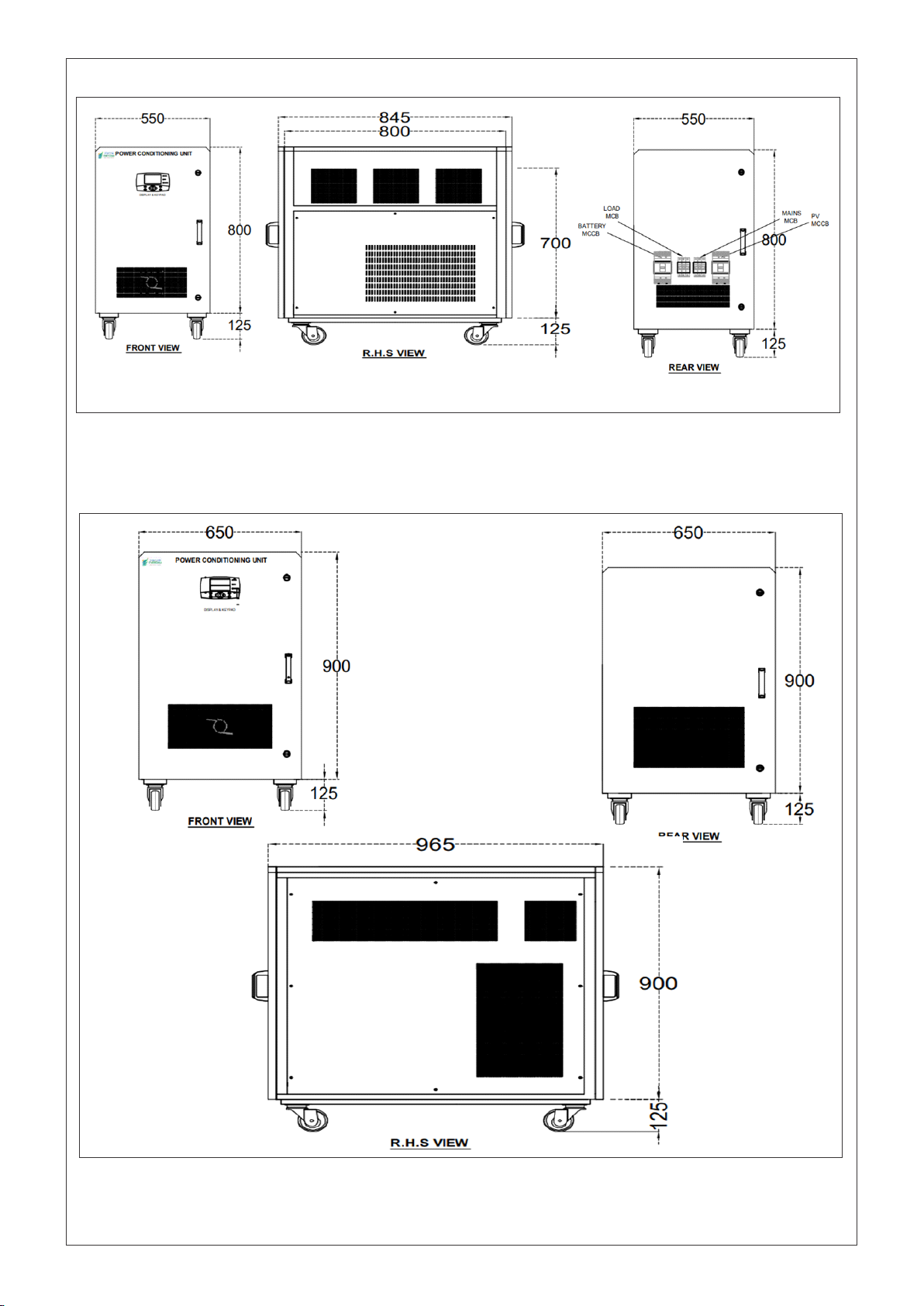
2.5 PHYSICAL APPEARANCE AND TERMINATION DETAILS OF INVERTERS
MONOPOWER/ TRIPOWER series of HBD-NG inverters come in sheet metal enclosures of standard sizes and
color shades depending upon the size of the machine. Any machine may be either wall mounted type, tower type,
floor standing, or hinged door type floor standing, depending upon the capacity of the machine. All the units are for
indoor application only and should not be kept in the open. All these units are forced cooled until mentioned
otherwise for any of the models supplied.
All the units have a common user interface provided on the front side of the panel for ease of access. The display
unit has been explained in detail separately in this manual. All the wire connections to unit are made from the
bottom side, either on the front or the rear side, depending upon the size of the machine. The terminology and
sequence of terminals have been kept the same for as many models as possible for ease of understanding and
has been explained below in detail.
The below chart brings out all the variants available in terms of dimensions and capacity of the machine. These
machines come in 8 basic variants:
Sr. No.
Rating of
Machine
Dimensions
(W X D X H)
Enclosure
Type
Colour
Shade
Cable
Entry
Wheels
Available
Y/N
Figure
No.
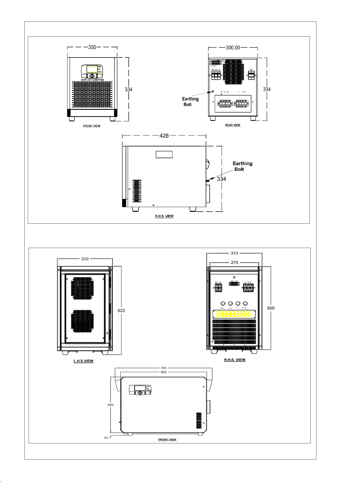
1
1-3kVA
Single-phase
Inverters
300 X 428 X 334
Tower Type
Floor
Standing
RAL-9005
Rear
Bottom
N
Figure-4
2
4-6kVA
Single-phase
Inverters
310 X 625 X 500
Tower Type
Floor
Standing
RAL7035/
RAL3020
Rear
Bottom
N
Figure-5
3
10kVA-12.5kVA
Single-phase
Inverters
400X676.5X650
Sheet Metal,
Floor
Standing,
Front/ Rear
Door
RAL7035/
RAL3020
Front
Bottom
N
Figure-6
4
10kVA-15kVA
Three-
phase/20kVA-
25kVA Single-
phase
Inverters
530X897.4X750
Sheet Metal,
Floor
Standing,
Front/ Rear
Door
RAL7035/
RAL3020
Front
Bottom
Y
Figure-7
5
20kVA-25kVA
Three-phase
Inverters
550X845X800
Sheet Metal,
Floor
Standing,
Front/ Rear
Door
RAL7035/
RAL3020
Front
Bottom
Y
Figure-8
6
30kVA-40kVA
Three-phase
Inverters with
Single/Three
MPPT Charge
Controller
650 X 965 X 900
Sheet Metal,
Floor
Standing,
Front/ Rear
Door
RAL7035/
RAL3020
Front
Bottom
Y
Figure-9

9
Sr. No.
Rating of
Machine
Dimensions
(W X D X H)
Enclosure
Type
Colour
Shade
Cable
Entry
Wheels
Available
Y/N
Views
7
50kVA-60kVA
Three-phase
Inverters with
Single/ Three
MPPT Charge
Controller
850X1050X1650
Sheet Metal,
Floor
Standing,
Front/ Rear
Door
RAL7035/
RAL3020
Front
Bottom
N
Figure-
10
8
70kVA-100kVA
Three-phase
Inverters with
Three MPPT
Charge
Controller
800 X 1050 X
1775
Sheet Metal,
Floor
Standing,
Front/ Rear
Door
RAL7035/
RAL3020
Front
Bottom
N
Figure-11
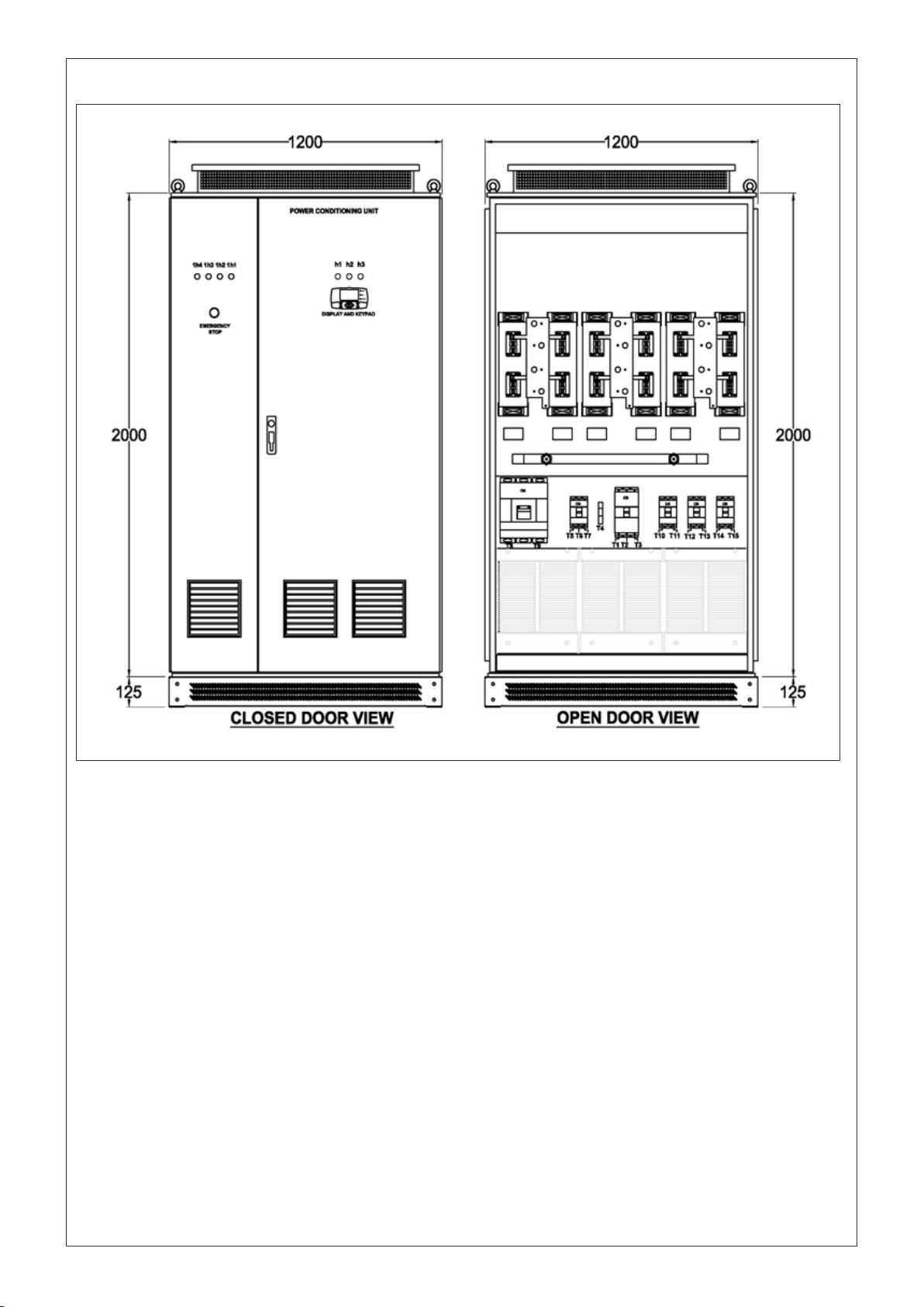
9
Above 100kVA
Three-phase
Inverters with
Three MPPT
Charge
Controller
2000X1400X1200
Sheet Metal,
Floor
Standing,
Front/ Rear
Door
RAL7035/
RAL3020
Front
Bottom
N
Figure-
12
Table 3
Please note that dimensions, weight, enclosure type, color shade and cable entry can be changed by the
manufacturer without prior notice. This is due to technical innovations.
Now we go through the front and rear view of each of these variants in detail. The termination details of each of
these variants are also provided in tabular form, after each variant drawing.
10
2.5.1 1kVA-3kVA SINGLE-PHASE INVERTER WITH SINGLE CHANNEL MPPT CHARGE CONTROLLER
2.5.2 4kVA-6kVA SINGLE-PHASE INVERTER WITH SINGLE CHANNEL MPPT CHARGE CONTROLLER
Figure 4
Figure 5

11
2.5.3 7.5kVA & 8kVA 10kVA-12.5kVA SINGLE-PHASE INVERTER WITH SINGLE CHANNEL MPPT CHARGE
CONTROLLER
Figure 6
Figure 7
2.5.4 10kVA-15kVA SINGLE-PHASE/ THREE-PHASE INVERTER WITH SINGLE CHANNEL MPPT CHARGE
CONTROLLER
12
2.5.5 20kVA-25kVA SINGLE-PHASE INVERTER WITH SINGLE CHANNEL MPPT CHARGE CONTROLLER
Figure 8
Figure 9
2.5.6 30kVA-40kVA SINGLE-PHASE/THREE-PHASE INVERTER WITH SINGLE MPPT CHARGE CONTROLLER

Figure 11
13
2.5.7 50kVA-60kVA SINGLE-PHASE/THREE-PHASE INVERTER WITH SINGLE/THREE MPPT CHARGE
CONTROLLER
Figure 10
2.5.8 70kVA-100kVA THREE-PHASE INVERTER WITH SINGLE MPPT CHARGE CONTROLLER
14
2.5.9 ABOVE THAN 100kVA THREE-PHASE INVERTER WITH THREE CHANNEL MPPT CHARGE CONTROLLER
Figure 12
15
3. INSTALLATION
3.1 UNPACKING AND CONTENTS INSIDE
Precautions are mandatory to prevent any damage due to mishandling or water ingress. Manufacturer shall not
be responsible for any such damage during transport, unloading or storage at site.
Please take a few moments to unpack your new HBD-NG range of Smart Storage Solar Inverter according to the
Following steps:
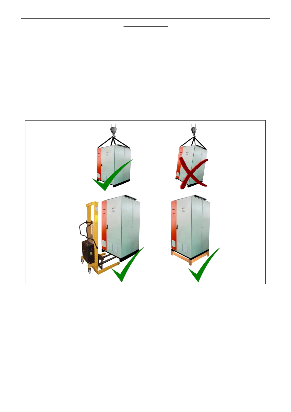
1. Unpack the wooden packing carefully. Be careful as there may be sharp edges or nails. Ensure the unit does
not incur any scratch during unpacking.
2. Use a crane to unload the machine in case of higher capacity machines. Proper lifting hooks have been
provided to lift the machine using a crane as shown below (applicable for larger machines only).
3. Ensure the machine is always lifted vertically without tilting on any side to prevent any damage inside.
4. Check whether unloading or unpacking should be done first in case of large machines depending upon the
condition.
5. Use always a forklift to move the inverters from one location to other location as shown in the figures
above.
6. Ensure the unit is placed on a raised wooden pallet. It will ensure better cable entry through bottom and also
give an increased level of insulation.
7. Verify the contents inside. It should include the SSSI unit, a hard copy of product manual for Installation and
Commissioning which is also, and a warranty card. Please note that any extra accessories such as
communication cable, mounting/ grouting hardware, or termination hardware, is a not a part of supply and is
under the scope of customer or to be bought at extra cost.
8. Go through the rating plate/rating sticker and verify that the model no. matches the model no. that was
ordered. In case of any issue related to model no. or rating, refer to the section 2 of this manual.
9. Please open the doors of the inverter to check there are no hanging wires/ connectors that may have resulted
during the transport. This is just to be sure about the readiness of the unit before being powered up. In case
something does not look okay, please contact the after sales/servicing department or your installer/dealer.
Figure 13

16
3.2 PLACEMENT AND LOCATION
Placement and location of the machine is very important for the machine and the plant both:
Following points should be kept in mind while placing this machine:
1. This machine has high voltages of both AC and DC nature inside and hence should be kept away from access of
children, infants or pets. Proper caution marks should be displayed close by to avoid any accidental conditions.
Location should be chosen accordingly.
2. This machine may be hot during operation and hence, its location should be such that any accidental, contact
with it should be avoided.
3. The room where this machine is placed should be of stationary nature with firm walls, base and roof. It should
be well ventilated with a proper mechanism of fresh air entry and exhaust. Air conditioned room will ensure a
more reliable functioning of this machine.
4. Minimum clearances should be maintained on all four sides as per the given diagram below for ease of access.
Ensure both front and rear door can easily be opened without obstruction. Sufficient space should be provided
between the roof of the room and the top of this unit (atleast 2.5 feet). This is important to avoid creation of hot
air column on top of the unit. Placing the PCU just below the solar panels will also damage the inverter, as the
heat source is directly above it. Ventilation is mandatory.
5. All the units have cable entry from bottom side. Proper route of cables should be envisaged before the
placement of the machine. It is important that none of the wires are in tension or hinder the path of movement
of people around.
6. The machine should be placed preferably on a raised platform for easy route of all incoming and outgoing
cables. It is recommended also for better insulation from ground.
7. The surface used for placing the machine should be horizontal and level. Proper grouting of the panel is
recommended on the holes provided on the base channels of this machine.
8. This machine is inflammable in nature and hence no high pressure items such as gas cylinders, gas pipe lines,
sprays, hay etc should be close by. Please ensure presence of a fire extinguisher close by in case of
emergency.
9. Once the machine has been firmly secured in its place, open the front and rear doors of the unit using the
proper tool provided along with the machine (Optional). Remove the Silica Gel packets from inside (if any).
Please check the fans for Silica Gel so that the running of fan is not hindered during operation.
Figure 14
Figure 15
2.5 FEET2.5 FEET
2.5 FEET
2.5 FEET
TOP VIEW

17
3.3 WIRING PROCEDURES AND ROUTES
Before making any electrical connections to the machine, selection of wire gauge and wire type is very important.
Any compromise with the wire selection will compromise with the efficiency as well as the safety of the plant.
Proper color coding of cables is recommended as per IEC standards throughout the plant. However, the chart
provided is only for assistance and no reference shall be made to it in case of any discrepancy later on.
Follow the procedure in below steps for making electrical connections.
1. All the connections to this machine are done through bottom cable entry only. Hence, no wires should be
hanging. Proper routing of cables through trench is mandatory.
2. Open the front door and locate the gland plate at the front bottom surface of the machine. The gland plate will
have several glands which can be loosened for cable entry.
3. Route all the cables through the bottom of the machine, through the glands and then into the machine.
4. Ensure too many cables are not clustered around the base or inside of the unit as it may hinder easy opening of
the door when required.
5. Ensure that all the circuit breakers/ MCBs/ MCCBs/ Dis-connectors are in OFF position before any connections
are made.
6. Locate the terminals provided for connecting the incoming cables. All the terminals are of bus bar type with
ring type/ pin type connections. Information about the terminal sizes is part of the technical datasheet provided
during ordering stage.
7. Connections of DC should be made first. In case of DC, always connect the negative first and then connect the
positive side.
8. All cables should be routed through the gland located directly below that terminal. This is recommended for
maintaining clearances between the cables. All the cables should be vertically aligned with their respective
terminals.
9. Use proper stripping and crimping tool for the cable termination. Any loose connections or wrong hardware
sizing issues may lead to lose contacts ultimately leading to fire hazards.
10. Once all the cables have been crimped properly, we can start making connections between the incoming
cables and terminals.
Refer to the figure as per enclosure as to locate the various terminals provided. A common sequence of
terminals is provided in all the machines with same type of numbering.
Always start with battery connections. Locate DC (-) terminal to make connections followed by DC (+)
terminals.
Now connect the PV (-) followed by PV (+) cables. There may be one or three nos. of MPPT chargers depending
upon the capacity of system. In case of multi MPPT charger machine, repeat PV connection for all 3 MPPT
sections.
Connect the AC Line and neutral terminals now. In case of three-phase systems, ensure proper phase
sequence is followed. Neutral should always be connected to Neutral terminal only.
Lastly, connect the load terminals in proper sequence.
Neutral of Grid and Neutral of Loads is connected to a common point to maintain the continuity of Neutral under
all circumstances.
11. Use proper nut/ bolts/ washers for connecting the cables to the Terminals provided in the machine. Please be
noted that use hardware of recommended sizes only. Proper contact is required between the cable, cable lugs
and the terminals. Any issues may lead to heating of contacts ultimately leading to fire hazards.
12. All terminals provided are of copper material only. Hence lugs used should be of copper only for homogeneity
of contact. In case of Aluminium cable, bimetallic lugs are mandatory.
13. Use proper spanners to tighten the nut/ bolts. Ensure that once tightened, all the lugs should be vertical. The
conductors are carrying high currents and voltages; hence clearances between them should be maintained.
14. Double check all the connections for polarity and type to avoid any malfunction later on.
15. Double check the tightness of all the nut and bolts.
16. It is recommended to route AC and DC cables with some minimum clearances in between.

3.4 EARTHING OR GROUNDING THE MACHINE
Connecting the inverter machine to earth is not only recommended but mandatory to avoid any electrical shock as
well as proper functioning of the electronics. The primary reason for earthing any equipment is to ensure that the
chassis of the equipment is always at ground potential and there is no experience of shock in case of human
contact. The same is valid of these inverters as well. All the inverters are provided with a proper connection point
in form of an earth bus bar or a terminal. The location of this point may vary from inverter to inverter. Please note
the below points with respect to the grounding of the equipment.
1. Hybrid inverters have an isolation transformer inbuilt and hence, can have a common AC side and DC side
grounding.
2
2. Always ground the inverter using a minimum of 6mm copper cables. Avoid using aluminum cable for
grounding of inverters.
3. All the shields of shielded cables inside the machine are also connected to the same ground. It is important to
ground these shields for the EMI/ EMC compatibility of the inverter.
4. SPD/MOV provided inside may not perform the intended function in case the inverters are not grounded
properly.
5. The inverter ground should be connected to the earth potential of the site to which all the other appliances of
the site are connected.
6. Inverter ground should not be connected to the PV structure ground or the lightning arrestor ground.
Avoid the contact with inverter if barefoot even if the machine is grounded properly. The body of the inverter may
still be live with AC and DC voltages.
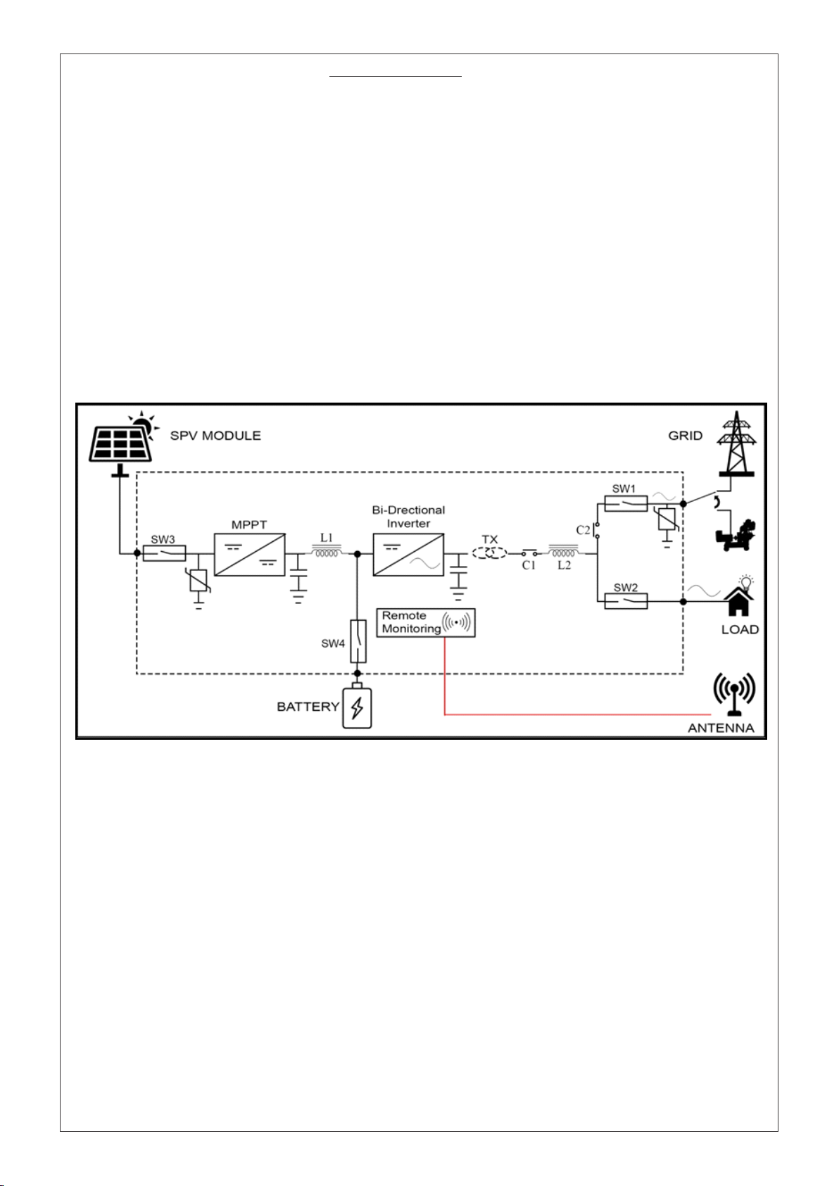
3.5 SURGE PROTECTION DEVICE (SPD)
Surge Protections are a part of plant installations and hence, should be installed in addition to protections
offered in PCU. Type and size of surge protections vary from site to site and adequate consultation should be
done with a subject matter expert before selection of SPD.
Apart from SPD in AJB used for solar panel protection, additional SPD is recommended before PCU inside the
room.
Suitable SPD on AC side (both Grid and Load) is mandatory inside the room before PCU to avoid any damage to
it caused by surges. A typical such schematic drawing can be seen in figure below for single phase as well as
three-phase PCU. An installer may contact some expert and use alternate scheme similar to this for reliable
working of PCU and site.
See the images below for reference:
18

19
This image shows a typical single-line diagram showing use of SPD and earth connection thereof for single
phase.
Figure 16
Table of contents
Other STATCON ENERGIAA Solar Panel manuals

Popular Solar Panel manuals by other brands


Steinbach
Steinbach Curve owner's manual

Steinbach
Steinbach speedsolar Sun 00-49120 manual

Clenergy
Clenergy PV-ezRack SolarTerraceIII-A Planning and installation

Link Energy
Link Energy Pilot Series installation guide

Westinghouse
Westinghouse AC System installation guide

Waterboy
Waterboy MIDI ARRAY Installation

Panasonic
Panasonic HIT Power 240S Series General installation manual

Solahart
Solahart HSL60P6-PB-1-250 Owner's guide and installation instructions

Sonnenkraft
Sonnenkraft SKR500 Series manual

NOMA
NOMA 011-2033-4 instruction manual

LG
LG LG Q1K-V5 Series installation manual

ALLTO SOLAR
ALLTO SOLAR SE-US-120W-F user manual