Solahart HSL60P6-PB-1-250 Technical Document
Solahart PV Systems must be installed and serviced by a suitably qualified person.
Please leave this guide with the PV system owner.
Owner’s Guide
and
Installation Instructions
Single-Phase PV Systems

PATENTS
This PV System may be protected by one or more patents or registered designs in the name of
Solahart Industries Pty Ltd.
TRADE MARKS
® Registered trademark of Solahart Industries Pty Ltd.
™ Trademark of Solahart Industries Pty Ltd.
Note: E ery care has been taken to ensure accuracy in preparation of this publication.
No liability can be accepted for any consequences, which may arise as a result of its application.
Warning: For continued safety of this PV System, it must be installed, operated and maintained in
accordance with these instructions and the installation guide supplied with the PV inverter.
Caution: Only qualified and accredited personnel should perform work on PV systems, such as design,
installation, commissioning, maintenance and repairs. e sure to follow the safety instructions for all system
components. It is also important to observe relevant local codes and regulations for health and safety and
accident prevention.
Only Solahart parts and Solahart approved parts may be used. No substitute parts may be used
without prior approval from Solahart Industries Pty Ltd. Only parts supplied by Solahart Industries
Pty Ltd are overed by the Solahart warranty.
The warranty an be ome void if safety devi es are tampered with or if the installation is not in
a ordan e with these instru tions.

ABOUT YOUR PV SYSTEM
3
CONTENTS
PV SYSTEM OWNER – We recommend you read pages 4 to 7.
The other pages are intended for the installer but may be of interest.
Contents .......................................................................................................................................
About Your PV System ............................................................................................................... 4
Operating Procedures ................................................................................................................. 5
Electrical Safety ........................................................................................................................... 5
Periodic Maintenance ................................................................................................................. 6
Wiring Diagrams .......................................................................................................................... 8
Installation Overview ................................................................................................................ 19
Installation Procedure ............................................................................................................... 21
Installation - Planning ............................................................................................................... 22
Installation - Racking ................................................................................................................ 27
Installation - Wiring ................................................................................................................... 4
Installation - Rooftop Isolator .................................................................................................. 6
Installation - PV Modules .......................................................................................................... 7
Installation - Inverter ................................................................................................................. 42
Installation - Labelling .............................................................................................................. 46
Installation - Commissioning ................................................................................................... 48
Engineering Certification .......................................................................................................... 5
Solahart PV System Warranty - Australia Only ...................................................................... 55
4
ABOUT YOUR PV SYSTEM
MODEL TYPE
Your Solahart PV System is designed for the polycrystalline photovoltaic modules to be roof and/or stand
mounted with the inverter installed in a serviceable position and connected to the electrical distribution grid
(often referred to as ‘the grid’) as per AS 4777.1. These instructions together with the installation instructions
supplied with the inverter give limitations on positioning of the inverter.
This Owner’s Guide and Installation Instructions applies to the following PV modules:
HSL60P6-P -1-250 (250 W module) REC255PE (255 W module)
Note: Unless approved otherwise by Solahart, only modules of the same make and model may be used in
Solahart PV systems.
SYSTEM OPERATION
The Solahart PV System is comprised of two main components; a string or array of photovoltaic modules
and an inverter.
The photovoltaic (PV) modules transform solar radiation into electrical energy in the form of direct current
(DC). In order to utilise this energy and feed it back into the grid, the direct current is transformed into
alternating current (AC) by the inverter. This conversion is also known as DC to AC inversion.
The alternating current generated by the inverter is fed into the main switchboard, which in turn is connected
to the grid.
Note: For safety reasons, the inverter will only operate when the mains electrical supply is available from the
grid. Your Solahart PV System cannot provide a backup electricity supply to your home appliances if the
mains supply is interrupted.
If the energy generated by the PV System is not sufficient to meet domestic demands, the energy necessary
to ensure the standard operation of the connected devices is drawn from the grid.
If the energy generated exceeds that required by property demands, your electrical network operator may
allow the difference to be directly injected into the grid and become available to other users. Energy injected
into the grid can be measured by electricity network operators as either gross (everything generated) or net
(excess generated). Injected energy may or may not be purchased by the local electrical network operator
according to national and local standards, and regulations.
SYSTEM OVERVIEW
• A photovoltaic module is composed of many photovoltaic cells assembled on the same frame.
• A string is composed of a certain number of modules electrically connected in series.
• An array is composed of one or more strings connected in parallel.
• The inverter converts direct current produced by the array into alternating current.
• The PV Array DC Isolators provide a means for isolating the array.
• The Inverter AC Isolator provides overcurrent protection of the inverter and a method of isolating the PV
System from the electrical distribution grid.
Warning: For the inverter to be effectively electrically isolated, both the PV Array DC Isolator(s) and the
Inverter AC Isolator(s) must be in the OFF position.
5
OPERATING PROCEDURES
TO TURN PV SYSTEM ON
1. Turn on the PV Array DC Isolator(s) at the inverter.
2. Then turn on the Inverter AC Isolator at the inverter (if installed) and the Solar Supply Main Switch at the
AC switchboard.
TO TURN PV SYSTEM OFF
1. Turn off the Solar Supply Main Switch at the AC switchboard and the Inverter AC Isolator at the inverter
(if installed).
2. Then turn off the PV Array DC Isolator(s) at the inverter.
Warning: Depending upon the system there may be more than one PV Array DC Isolator.
Warning: To effectively isolate the wiring between the AC isolator and switchboard, the Solar Supply
Main Switch located in the switchboard must also be in the off position.
Warning: PV array DC isolators do not de-energise the PV array and array cabling.
ACTIONS TO UNDERTAKE IN THE EVENT OF AN EARTH FAULT ALARM
1. Limit access to all parts of the PV system
2. Contact Solahart Service on 1800 638 011 or your nearest Solahart dealer.
ELECTRICAL SAFETY
SAFETY REQUIREMENTS
The voltages and currents produced by a single module or modules connected in series (voltages are added
together) or in parallel (currents are added together) can be dangerous.
Note: Only qualified personnel should perform work on photovoltaic systems.
UNIQUE HAZARDS OF DC ELECTRICITY
PV modules generate DC electricity as soon as they are exposed to sunlight. Once the current is flowing,
breaking or opening a connection (e.g. disconnecting a DC cable from the inverter) can cause a DC
electrical arc. Unlike arcs occurring in conventional low voltage AC wiring, DC arcs are not self-extinguishing.
They are a potentially lethal burn and fire hazard, capable of creating high temperatures that can destroy
contacts and connectors.
EARTH FAULTS
An earth fault is a system fault where a short circuit is formed between the DC circuitry of the PV system and
earth. As the PV system owner, please be aware of the current method of communication of earth faults on
your system. Refer to Earth Fault Alarms on page 44 for details.
6
PERIODIC MAINTENANCE
GENERAL
Due to the safety concerns involved with working at heights and working with electricity, we recommend the
householder follow the maintenance schedule provided below. Other maintenance should be performed by a
suitably qualified person, such as a CEC accredited installer. ustralian Standard S/NZS 5033 provides a
recommended maintenance schedule for PV systems.
Modules supplied by Solahart have been designed for easy maintenance. Normal rainfall should naturally
clean the modules. The need for cleaning will vary with the location of the installation, amount of rainfall,
pollution and inclination of the modules.
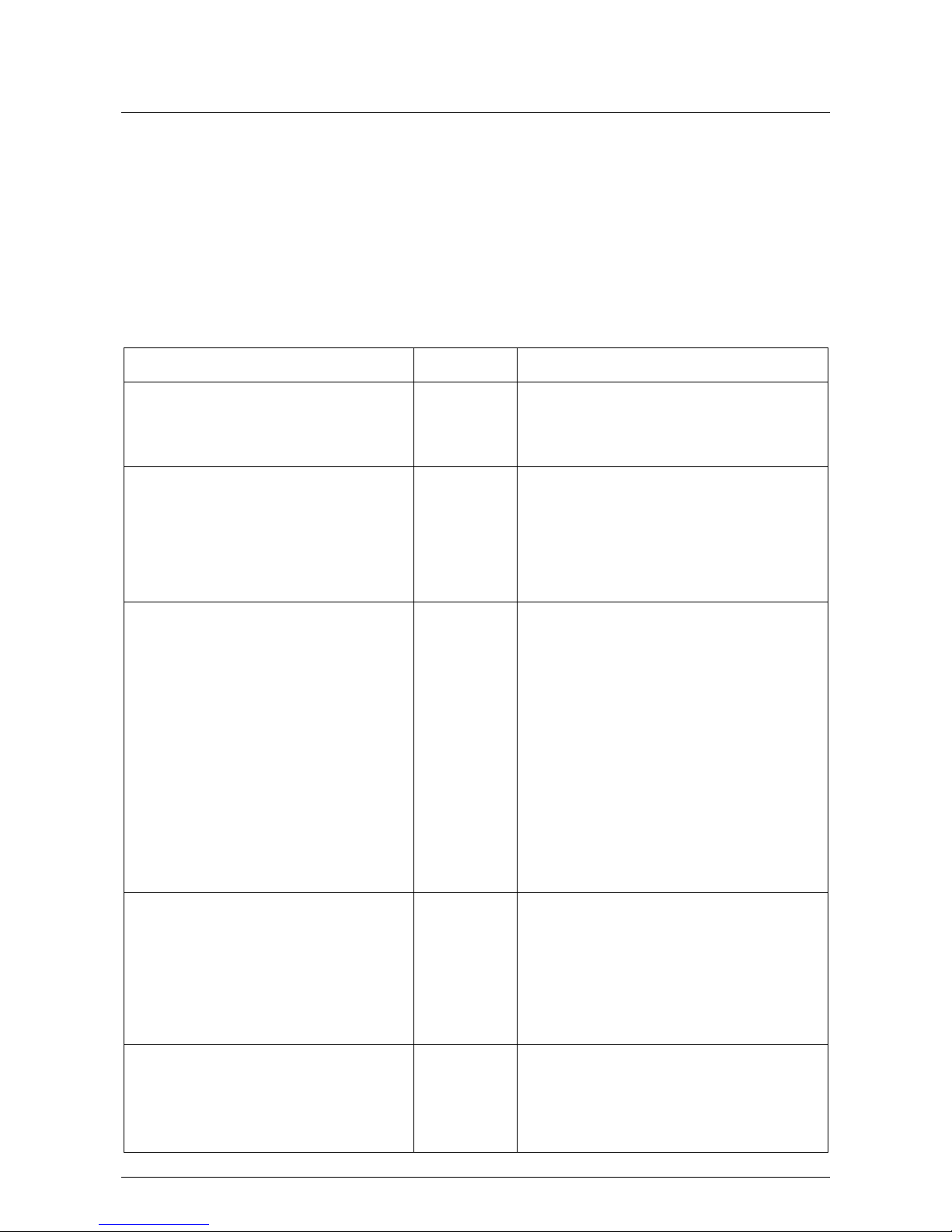
RECOMMENDED MAINTENANCE SCHEDULE
Maintenance Action Frequency Remarks
Under daylight conditions check that your
inverter is operating correctly (refer to the
Inverter Manufacturer’s manual for
details).
Weekly If not operating correctly, contact your
Solahart dealer.
If you have a communications device
installed, such as the SM Webconnect or
BB Wi-Fi logger card, log in to your
inverter manufacturer’s web portal and
check that your system is operating, data
has been logged and communication has
been maintained.
Monthly If you are unable to log in or your system is
not operating correctly, contact your Solahart
dealer.
Visual inspection of PV system
components from ground level, to check
for:
Quarterly
• ccumulation of debris around
components.
Gently remove debris from components that
are safely accessible from ground level.
• Shading of the array. Trim trees, if required.
• Visible damage to any components. Contact your Solahart dealer.
• Cleanliness of PV modules. To optimize electrical output, it is
recommended that the modules are cleaned
when dirt can be seen on the glass surface.
Please contact your Solahart dealer to
arrange module cleaning.
If you have a communications device
installed, such as the SM Webconnect or
BB Wi-Fi logger card, log in to your
inverter manufacturer’s web portal and
ensure that the contact details of the PV
system owner or responsible officer are up
to date to ensure that inverter fault
notifications are delivered.
Quarterly If you are unable to log in, contact your
Solahart dealer.
Contact a suitably qualified person, such
as a CEC accredited installer, to inspect
the system.
Yearly This inspection can be arranged through your
Solahart dealer, and should ensure that:
• Inverter’s ventilation filters and fans are
cleaned.
• ll fastenings are tight, secure and free
PERIODIC MAINTENANCE
7
of corrosion.
• ll cable connections are tight, secure
and free of corrosion.
• Cables are not damaged in any way.
• Earthing of the modules and module rails
is satisfactory.
• Electrical characteristics are within
specification.
• The C and DC isolator/circuit breakers
function correctly.

8
WIRING DIAGRAMS
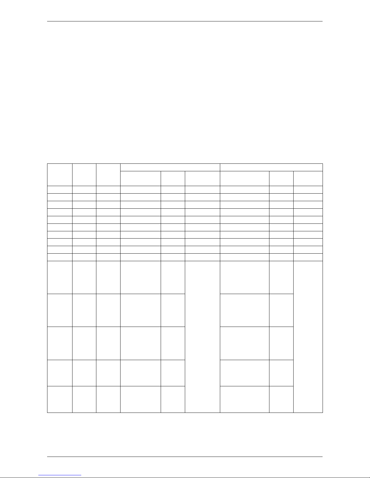
SB 1.5-1 VL-40 INVERTER SYSTEMS
Number
of
Modules
Number
of
Strings
Modules
per
String
HSL60P6-PB-1-250 Modules REC255PE Modules
System Power
Rating (W) * Isc ( )*
Voc (V)*
System Power
Rating (W) * Isc ( )* Voc (V)*
4 1 4 1000 8.79 150.8 1020 8.95 150.4
5 1 5 1250 8.79 188.5 1275 8.95 188.0
6 1 6 1500 8.79 226.2 1530 8.95 225.6
7 1 7 1750 8.79 263.9 1785 8.95 263.2
* Values measured at standard test conditions (STC) defined as: irradiance of 1000 W/m2, Spectrum M 1.5
and cell temperature 25ºC. Variations from STC values will affect actual Isc and Voc and should be allowed
for.
For earthing arrangement and wiring diagram refer to “Earthing rrangements – ll Systems” on page 18.

WIRING DIAGRAMS
9
SB1600TL-10 INVERTER SYSTEMS
Number
of
Modules
Number
of
Strings
Modules
per
String
HSL60P6-P -1-250 Modules REC255PE Modules
System Power
Rating (W) * Isc (A)*
Voc (V)*
System Power
Rating (W) * Isc (A)* Voc (V)*
6 1 6 1500 8.79 226.2 1530 8.95 225.6
7 1 7 1750 8.79 263.9 1785 8.95 263.2
* Values measured at standard test conditions (STC) defined as: irradiance of 1000 W/m2, Spectrum AM 1.5
and cell temperature 25ºC. Variations from STC values will affect actual Isc and Voc and should be allowed
for.
For earthing arrangement and wiring diagram refer to “Earthing Arrangements – All Systems” on page 18
WIRING DIAGRAMS
10
UNO-2.0-I-OUTD
Number
of
Modules
Number
of
Strings
Modules
per
String
HSL60P6-P -1-250 Modules REC255PE Modules
System Power
Rating (W) * Isc (A)*
Voc (V)*
System Power
Rating (W) * Isc (A)* Voc (V)*
6 1 6 1500 8.79 226.2 1530 8.95 225.6
7 1 7 1750 8.79 263.9 1785 8.95 263.2
8 1 8 2000 8.79 301.6 2040 8.95 300.8
9 1 9 2250 8.79 339.3 2295 8.95 338.4
10 1 10 2500 8.79 377.0 2550 8.95 376.0
* Values measured at standard test conditions (STC) defined as: irradiance of 1000 W/m2, Spectrum AM 1.5
and cell temperature 25ºC. Variations from STC values will affect actual Isc and Voc and should be allowed
for.
For earthing arrangement and wiring diagram refer to “Earthing Arrangements – All Systems” on page 18.
WIRING DIAGRAMS
11
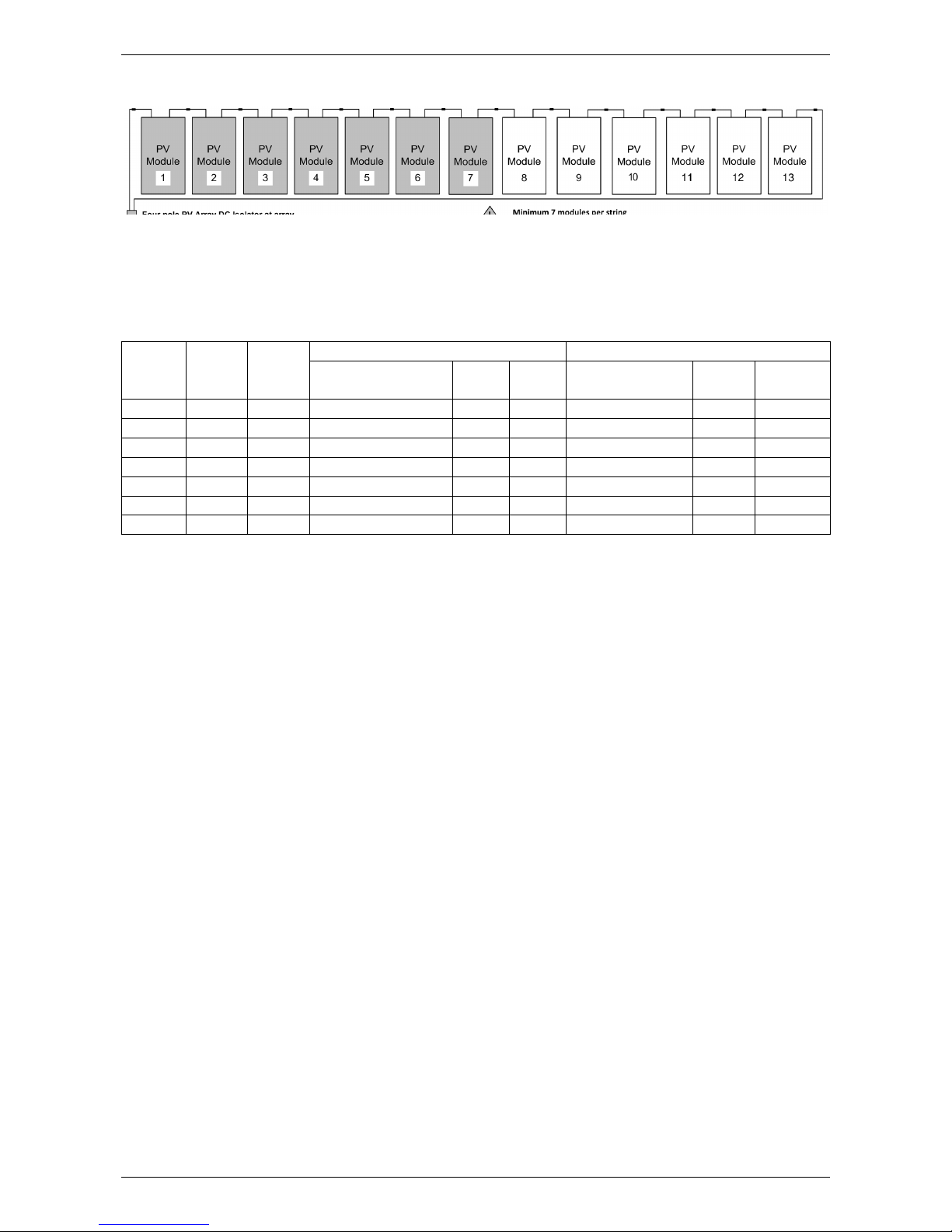
SB 2.5-1 VL-40 INVERTER SYSTEMS
Number
of
Modules
Number
of
Strings
Modules
per
String
HSL60P6-PB-1-250 Modules REC255PE Modules
System Power
Rating (W) * Isc ( )*
Voc (V)*
System Power
Rating (W) * Isc ( )* Voc (V)*
7 1 7 1750 8.79 263.9 1785 8.95 263.2
8 1 8 2000 8.79 301.6 2040 8.95 300.8
9 1 9 2250 8.79 339.3 2295 8.95 338.4
10 1 10 2500 8.79 377.0 2550 8.95 376.0
11 1 11 2750 8.79 414.7 2805 8.95 413.6
12 1 12 3000 8.79 452.4 3060 8.95 451.2
13 1 13 3250 8.79 490.1 3315 8.95 488.8
* Values measured at standard test conditions (STC) defined as: irradiance of 1000 W/m2, Spectrum M 1.5
and cell temperature 25ºC. Variations from STC values will affect actual Isc and Voc and should be allowed
for.
For earthing arrangement and wiring diagram refer to “Earthing rrangements – ll Systems” on page 18.

WIRING DIAGRAMS
12
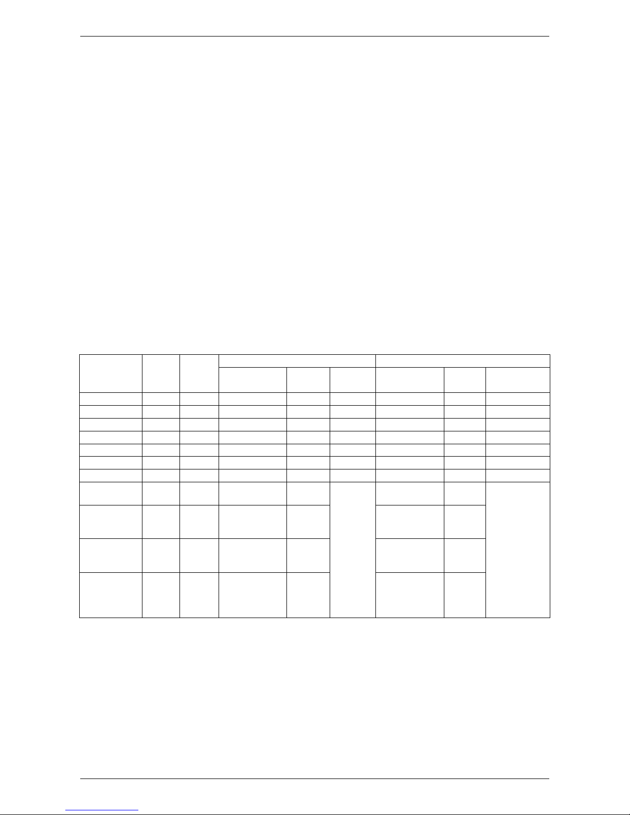
PVI-3.0-TL-OUTD INVERTER SYSTEMS
Number
of
Modules
Number
of
Strings
Modules
per
String
HSL60P6-P -1-250 Modules REC255PE Modules
System Power
Rating (W) * Isc (A)* Voc (V)* System Power
Rating (W) * Isc (A)* Voc (V)*
5 1 5 1250 8.79 188.5 1275 8.95 188.0
6 1 6 1500 8.79 226.2 1530 8.95 225.6
7 1 7 1750 8.79 263.9 1785 8.95 263.2
8 1 8 2000 8.79 301.6 2040 8.95 300.8
9 1 9 2250 8.79 339.3 2295 8.95 338.4
10 1 10 2500 8.79 377.0 2550 8.95 376.0
11 1 11 2750 8.79 414.7 2805 8.95 413.6
12 1 12 3000 8.79 452.4 3060 8.95 451.2
13 1 13 3250 8.79 490.1 3315 8.95 488.8
14 1 14 3500 8.79 527.8 3570 8.95 526.4
10 2 5 + 5 2500 8.79
Refer to string voltages
listed above
2550 8.95
Refer to string voltages
listed above
11 2 5 + 6 2750 8.79 2805 8.95
12 2 5 + 7
6 + 6 3000 8.79 3060 8.95
13 2 5 + 8
6 + 7 3250 8.79 3315 8.95
14 2
5 + 9
6 + 8
7 + 7
3500 8.79 3570 8.95
* Values measured at standard test conditions (STC) defined as: irradiance of 1000 W/m2, Spectrum AM 1.5
and cell temperature 25ºC. Variations from STC values will affect actual Isc and Voc and should be allowed
for.
For earthing arrangement and wiring diagram refer to “Earthing Arrangements – All Systems” on page 18.

WIRING DIAGRAMS
13
SB3000TL-21 INVERTER SYSTEMS
Number
of
Modules
Number
of
Strings
Modules
per
String
HSL60P6-P -1-250 Modules REC255PE Modules
System
Power
Rating (W) *
Isc (A)* Voc (V)* System Power
Rating (W) * Isc (A)* Voc (V)*
6 1 6 1500 8.79 226.2 1530 8.95 225.6
7 1 7 1750 8.79 263.9 1785 8.95 263.2
8 1 8 2000 8.79 301.6 2040 8.95 300.8
9 1 9 2250 8.79 339.3 2295 8.95 338.4
10 1 10 2500 8.79 377.0 2550 8.95 376.0
11 1 11 2750 8.79 414.7 2805 8.95 413.6
12 1 12 3000 8.79 452.4 3060 8.95 451.2
13 1 13 3250 8.79 490.1 3315 8.95 488.8
14 1 14 3500 8.79 527.8 3570 8.95 526.4
12 2 6 + 6 3000 8.79
Refer to
string
voltages
listed above
3060 8.95
Refer to
string
voltages
listed above
13 2 6 + 7 3250 8.79 3315 8.95
14 2 6 + 8
7 + 7 3500 8.79 3570 8.95
* Values measured at standard test conditions (STC) defined as: irradiance of 1000 W/m2, Spectrum AM 1.5
and cell temperature 25ºC. Variations from STC values will affect actual Isc and Voc and should be allowed
for.
For earthing arrangement and wiring diagram refer to “Earthing Arrangements – All Systems” on page 18.
WIRING DIAGRAMS
14
SB 000TL-21 INVERTER SYSTEMS
Number of
Modules
Number
of
Strings
Module
s
per
String
HSL60P6-P -1-250 Modules REC255PE Modules
System Power
Rating (W) * Isc (A)* Voc (V)* System Power
Rating (W) * Isc (A)* Voc (V)*
6 1 6 1500 8.79 226.2 1530 8.95 225.6
7 1 7 1750 8.79 263.9 1785 8.95 263.2
8 1 8 2000 8.79 301.6 2040 8.95 300.8
9 1 9 2250 8.79 339.3 2295 8.95 338.4
10 1 10 2500 8.79 377.0 2550 8.95 376.0
11 1 11 2750 8.79 414.7 2805 8.95 413.6
12 1 12 3000 8.79 452.4 3060 8.95 451.2
15 2 6 + 9
7 + 8 3750 8.79
Refer to string voltages
listed above
3825 8.95
Refer to string voltages
listed above
16 2
6 + 10
7 + 9
8 + 8
4000 8.79 4080 8.95
17 2
6 + 11
7 + 10
8 + 9
4250 8.79 4335 8.95
18 2
6 + 12
7 + 11
8 + 10
9 + 9
4500 8.79 4590 8.95
* Values measured at standard test conditions (STC) defined as: irradiance of 1000 W/m2, Spectrum AM 1.5
and cell temperature 25ºC. Variations from STC values will affect actual Isc and Voc and should be allowed
for.
For earthing arrangement and wiring diagram refer to “Earthing Arrangements – All Systems” on page 18.

WIRING DIAGRAMS
15
PVI- .2-TL-OUTD INVERTER SYSTEMS
Number of
Modules
Number
of
Strings
Modules
per
String
HSL60P6-P -1-250 Modules REC255PE Modules
System Power
Rating (W) * Isc (A)* Voc (V)* System Power
Rating (W) * Isc (A)* Voc (V)*
5 1 5 1250 8.79 188.5 1275 8.95 188.0
6 1 6 1500 8.79 226.2 1530 8.95 225.6
7 1 7 1750 8.79 263.9 1785 8.95 263.2
8 1 8 2000 8.79 301.6 2040 8.95 300.8
9 1 9 2250 8.79 339.3 2295 8.95 338.4
10 1 10 2500 8.79 377.0 2550 8.95 376.0
11 1 11 2750 8.79 414.7 2805 8.95 413.6
12 1 12 3000 8.79 452.4 3060 8.95 451.2
13 1 13 3250 8.79 490.1 3315 8.95 488.8
15 2
5 + 10
6 + 9
7 + 8
3750 8.79
Refer to string voltages
listed above
3825 8.95
Refer to string voltages
listed above
16 2
5 + 11
6 + 10
7 + 9
8 + 8
4000 8.79 4080 8.95
17 2
5 + 12
6 + 11
7 + 10
8 + 9
4250 8.79 4335 8.95
18 2
5 + 13
6 + 12
7 + 11
8 + 10
9 + 9
4500 8.79 4590 8.95
* Values measured at standard test conditions (STC) defined as: irradiance of 1000 W/m2, Spectrum AM 1.5
and cell temperature 25ºC. Variations from STC values will affect actual Isc and Voc and should be allowed
for.
For earthing arrangement and wiring diagram refer to “Earthing Arrangements – All Systems” on page 18.
WIRING DIAGRAMS
16
PVI-5000-TL-OUTD INVERTER SYSTEMS
Number
of
Modules
Number
of
Strings
Modules
per
String
HSL60P6-P -1-250 Modules REC255PE Modules
System Power
Rating (W) * Isc (A)* Voc (V)* System Power
Rating (W) * Isc (A)* Voc (V)*
5 1 5 1250 8.79 188.5 1275 8.95 188.0
6 1 6 1500 8.79 226.2 1530 8.95 225.6
7 1 7 1750 8.79 263.9 1785 8.95 263.2
8 1 8 2000 8.79 301.6 2040 8.95 300.8
9 1 9 2250 8.79 339.3 2295 8.95 338.4
10 1 10 2500 8.79 377.0 2550 8.95 376.0
11 1 11 2750 8.79 414.7 2805 8.95 413.6
12 1 12 3000 8.79 452.4 3060 8.95 451.2
13 1 13 3250 8.79 490.1 3315 8.95 488.8
14 1 14 3500 8.79 527.8 3570 8.95 526.4
18 2
5 + 13
6 + 12
7 + 11
8 + 10
9 + 9
4500 8.79
Refer to string voltages
listed above
4590 8.95
Refer to string voltages
listed above
19 2
5 + 14
6 + 13
7 + 12
8 + 11
9 + 10
4750 8.79 4845 8.95
20 2
6 + 14
7 + 13
8 + 12
9 + 11
10 + 10
5000 8.79 5100 8.95
21 2
7 + 14
8 + 13
9 + 12
10 + 11
5250 8.79 5355 8.95
22 2
8 + 14
9 + 13
10 + 12
11 + 11
5500 8.79 5610 8.95
* Values measured at standard test conditions (STC) defined as: irradiance of 1000 W/m2, Spectrum AM 1.5
and cell temperature 25ºC. Variations from STC values will affect actual Isc and Voc and should be allowed
for.
For earthing arrangement and wiring diagram refer to “Earthing Arrangements – All Systems” on page 18.

WIRING DIAGRAMS
17
SB5000TL-21 INVERTER SYSTEMS
Number
of
Modules
Number
of
Strings
Modules
per
String
HSL60P6-P -1-250 Modules REC255PE Modules
System Power
Rating (W) * Isc (A)* Voc (V)* System Power
Rating (W) * Isc (A)* Voc (V)*
6 1 6 1500 8.79 226.2 1530 8.95 225.6
7 1 7 1750 8.79 263.9 1785 8.95 263.2
8 1 8 2000 8.79 301.6 2040 8.95 300.8
9 1 9 2250 8.79 339.3 2295 8.95 338.4
10 1 10 2500 8.79 377.0 2550 8.95 376.0
11 1 11 2750 8.79 414.7 2805 8.95 413.6
12 1 12 3000 8.79 452.4 3060 8.95 451.2
13 1 13 3250 8.79 490.1 3315 8.95 488.8
14 1 14 3500 8.79 527.8 3570 8.95 526.4
18 2
6 + 12
7 + 11
8 + 10
9 + 9
4500 8.79
Refer to string voltages
listed above
4590 8.95
Refer to string voltages
listed above
19 2
6 + 13
7 + 12
8 + 11
9 + 10
4750 8.79 4845 8.95
20 2
6 + 14
7 + 13
8 + 12
9 + 11
10 + 10
5000 8.79 5100 8.95
21 2
7 + 14
8 + 13
9 + 12
10 + 11
5250 8.79 5355 8.95
22 2
8 + 14
9 + 13
10 + 12
11 + 11
5500 8.79 5610 8.95
* Values measured at standard test conditions (STC) defined as: irradiance of 1000 W/m2, Spectrum AM 1.5
and cell temperature 25ºC. Variations from STC values will affect actual Isc and Voc and should be allowed
for.
For earthing arrangement and wiring diagram refer to “Earthing Arrangements – All Systems” on page 18.

WIRING DIAGRAMS
18
EARTHING ARRANGEMENTS – ALL SYSTEMS
Earthing connections must be made so the removal of one component (e.g. a module) does not interrupt the
earthing to other parts of a system (e.g. other modules). Daisy chaining is not permitted. The PV system
earth connection must be directly connected to the switchboard earth link, not via the inverter earth
connection. If the earth cable could be exposed to direct sunlight, it must have a physical barrier to protect
the earth cable from this exposure.
Earth wires must be sized in accordance with requirements set out in Earthing and bonding arrangements of
AS/NZS 5033.
Solahart approved earthing plates may be used to earth modules via the racking, instead of wiring directly to
the module frames. Refer to “Earthing” on page 38 for more information.
Warning: Do not drill holes in the modules as this will void product warranty.
The racking may be earthed by means of a rooftop isolator bracket. Refer to “Installation - Rooftop Isolator”
on page 36 for details.
Where it is necessary to make an earthing connection to a rail that does not have a rooftop isolator bracket
fitted, a rail splice piece will provide a suitable surface for connection. In this case, the splice should be
attached to the end of the rail using both fixing bolts, and then the earth lug connected to the splice as shown
in the figures below:
1. Slide rail splice onto end of rail, ensuring an overhang of approximately 50 mm.
2. Secure rail splice by tightening both Allen head bolts to 15 Nm.
3. Drill a hole in the centre of the rail splice, attach the earth cable using the earthing set supplied, and
tighten to 5 Nm.
Rail splice attached to rail with
both Allen head bolts
Earth cable connected to splice

19
INSTALLATION OVERVIEW
The following installation instructions detail installation procedures for photovoltaic modules, inverter, module
racking systems and balance of system (BOS) components.
Prior to the installation of any grid connected PV system, a Site Visit shall be performed in accordance with
the Clean Energy Council’s “Grid-Connected Solar PV Systems - Design Guidelines for ccredited
Installers”.
SAFETY REQUIREMENTS
The voltages and currents produced by a single module or modules connected in series (voltages added
together) or in parallel (currents added together) can be dangerous.
lthough module DC plug connectors are insulated to provide touch safe protection, the following points
must be observed when handling modules in order to avoid the risk of sparking, fire hazard, burn risk, and
lethal electric shocks:
• Exercise extreme caution when wiring modules and look out for damaged or split cable ends.
• Do not perform wiring work in rainy or damp conditions.
• Never insert metallic or otherwise conductive objects into plugs or sockets.
• Ensure that all electrical connections are completely dry and free from contaminants before they are
assembled.
• Ensure that connections are tight and correctly made.
• Keep all materials, tools and work areas clean and dry.
• lways use appropriate safety equipment such as insulated tools and wear personal protective
equipment such as insulated gloves.
• Solar modules produce current when exposed to sunlight. It is recommended that the system is shielded
with an opaque cover during installation, maintenance or repair work.
INSTALLER RESPONSIBILITIES
The installer is solely responsible for:
• Observing and conforming to all relevant ustralian Standards, all relevant Clean Energy Council
ccreditation guidelines and all applicable laws, ordinances, regulations, codes of practice and local or
national building codes, including any that may have superseded this Owner’s Guide & Installation
Instructions.
• Ensuring that the installation complies with S/NZS 3000, S/NZS 5033, S/NZS 1170.2, S/NZS
1562.1, S 4777.1, S/NZS 1768, S/NZS 3008, S 2050 and any relevant electrical service and
installation rules for the state or territory where the system is installed.
• Ensuring that the PV System and associated components are appropriate for the particular installation
and the installation environment.
• Ensuring that the roof, roof rafters, battens, purlins, connections, and other structural support members
can support the total assembly under building live load conditions. The roof on which the PV system is to
be installed must have the capacity to resist the combined Design Dead Load and Live Load at each
mounting point.
• Ensuring only parts supplied by Solahart Industries and installer supplied parts as specified by Solahart
Industries are utilised (substitution of parts may void the warranty and invalidate certification).
• Ensuring that lag screws have adequate pull-out strength and shear capacities to suit the installation.
• Maintaining the waterproof integrity of the roof, including selection of appropriate flashing.
• Ensuring safe installation of all electrical aspects of the PV system.

INSTALLATION OVERVIEW
20
DISCLAIMER OF LIABILITY AND WARRANTY
Solahart assumes no responsibility for loss, damage or expense resulting from improper installation,
handling or misuse of PV modules. Refer to “Solahart PV System Warranty - Australia Only” on page 55 for
full warranty terms and conditions.
IEC 61730 INFORMATION
Modules supplied by Solahart are designed to fulfil the criteria of application Class A requirements according
to IEC 61730. Modules are qualified for application Class A: Hazardous voltage (Higher than 50 V DC) and
hazardous power (higher than 240 W) applications where general contact access is anticipated. For the
purposes of AS/NZS 3000, modules are classified as Class I equipment.
FIRE GUIDELINES
Utilise the following fire safety guidelines when installing modules supplied by Solahart:
• Modules supplied by Solahart have a Class C Fire Rating.
• Check with local authorities for guidelines and requirements concerning fire safety for any building or
structure on to which the modules will be installed.
• The system design should ensure that fire fighting personnel can access the system in the event of a
building fire. Check with local authorities for any applicable regulations concerning setbacks or other
placement restrictions that may apply for roof-mounted PV arrays.
• Any electrical equipment can pose a fire risk. Modules must therefore be mounted over a fire retardant
roof covering rated for the application.
ENVIRONMENTAL FACTORS
Solahart’s limited warranty is based upon modules being installed in accordance with the following
conditions:
• Modules are not suitable for installation in potentially hazardous locations.
• Modules should not be installed in locations:
close to fire or combustible materials.
where there is potential for extreme sand and dust damage.
in direct contact with salt water/spray. Avoid installing in areas subject to high salt mist content e.g.
coastal areas.
exposed to extreme air pollution, chemical vapours, acid rain and/or soot, etc.
which experience extreme hail and/or snow.
where they may be exposed to sulphur e.g. near sulphur springs or volcanoes where they may be
exposed to harmful chemicals.
WARNINGS
Warning: This document provides sufficient information for system installation heights up to 10 m. If the
installation site is more than 10 m in height contact Solahart Industries for further advice.
Warning: This system has not been certified for, and should not be installed in, wind region D.
Warning: During installation and when working on the roof, be sure to observe the appropriate OH&S
safety regulations and relevant regulations of your local region.
Warning: Ensure electrical connection/ disconnection is performed only when the relevant circuit is
isolated. Do not connect / disconnect wiring under load conditions.
Warning: Do not expose the PV modules to artificially concentrated light.
Warning: Do not drill holes in the modules as this will void product warranty.
This manual suits for next models
1
Table of contents
Other Solahart Solar Panel manuals


