STAUFF STA-CK-305 User manual


2www.stauff.com
STA-CK-305
Operating Instructions available online
Only use “gas approved" test hose
For use with nitrogen (N2) gas only
Safety goggles must be worn at all times
STAUFF pressure gauges are safety pattern type according to AS1349
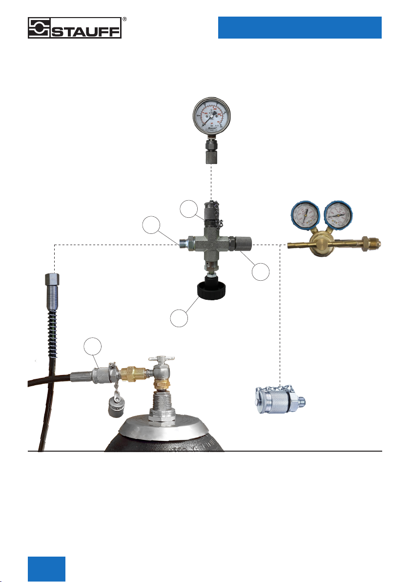
Product Description
STAUFF’s accumulator charging kit is designed to suit accumulators tted with gas valve type USA 0.305” x 32 TPI. It allows for the verication,
pressurisation and nitrogen gas bleeding of the accumulator. Pre-charge pressure can be easily checked by using STAUFF charging valve (1)
which combines a bleed valve, safety pattern gauge and 0.305” x 32 TPI charging chuck adaptor.
Features
The standard kit is delivered in a storage case containing the following:
11 x Charging valve
2
1 x STA-CK-CHRG-HEAD-0.305-SKK20 (for accumulator connection)
3
1 x SKK-20 Test coupling 1/4” NPT (for regulator connection)
4 1 x Safety pattern pressure gauge 0 - 250 bar (standard) according to AS1349
51 x 2000 mm hose
6
1 x Safety goggles
7 1 x Operating instructions
Available on request
▪0 - 25 and 0 - 100 bar kit
Application
▪For checking and pre-charging of accumulators with
gas valve type USA 0.305” x 32 TPI
Maximum working pressure of this equipment
(excluding individual pressure rating of gauges) is 207 bar.
7
1
54
6
32
www.stauff.com
STA-CK-305
3
Operating Instructions available online
Safety Instructions and Recommendations
1. Before using the charging head carefully read the directions and safety instructions in this guide.
2. In all cases observe the pressure limits indicated on the accumulator pressure vessels. If necessary refer to the applicable operating
instructions.
3. Before attempting to check the pre-charge pressure, the accumulator in the hydraulic circuit under pressure has to be isolated and
discharged on the hydraulic side. If required immobilize it and dene a safety zone.
4. Only use nitrogen gas with a purity ≥ 99,8% (N2) to pressurise the accumulator.
5. STAUFF always recommends the use of a nitrogen gas regulator on the nitrogen gas bottle.
6. The charging valve (1) incorporating pressure gauge (4) and charging chuck adaptor (2) are tools for checking gas pressure and
pre-charging pressure of accumulators only. These items are not designed to be permanently attached to the accumulator during
normal operation.
7. Never use an accumulator in a hydraulic system without it rst being pre-charged with the correct nitrogen gas pressure.
Failure to do this will result in bladder or diaphragm damage.
8. Ensure safety goggles are worn when either checking or pre-charging accumulators.
9. To ensure optimum efciency and performance of the hydraulic circuit, the pre-charge pressure must be checked frequently.
STAUFF recommends the pressure be checked initially at intervals of 1 month, 3 months and then 6 months after installation.
Depending on the amount of loss of pressure (if any) over this time, a planned maintenance schedule for monitoring the pressure
can then be put into operation (check annually).
Only use “gas approved" test hose
For use with nitrogen (N2) gas only
Safety goggles must be worn at all times
STAUFF pressure gauges are safety pattern type according to AS1349
Only use “gas approved" test hose
For use with nitrogen (N2) gas only
Safety goggles must be worn at all times
STAUFF pressure gauges are safety pattern type according to AS1349
4www.stauff.com
STA-CK-305
Operating Instructions available online
High Pressure Gas Hose DN4
Length: 2000 mm
Test 20 / 1/4” BSPP Connection
Connection Flow Chart
A
C
E
D
B
*
Pre-Charging -Typical Installation
USA 0.305” x 32 TPI
Charging Chuck Adaptor
STA-CK-CHRG-HEAD-0.305-SKK20
5
2
SKK-20 Test Coupling
1/4" NPT
(for regulator connection)
* Ensure appropriate thread sealing
compound is applied prior to
connection
3
Optional
STAUFF Recommend
the use of a Nitrogen
Gas Regulator
Safety Pattern
Pressure Gauge
+ Adaptor
SMD-20-G1/4
4
Charging Valve
1
www.stauff.com
STA-CK-305
5
Operating Instructions available online
General
1. Recommendation: Before proceeding to any operation concerning the initial pressurisation of an accumulator, consult the applicable
operating instructions.
2. Pressurisation limits: Ensure that the STA-CK-305 Charging Kit and any associated pressure gauge tted are rated for the intended
pressure for both pre-charging and pressure checking. Refer to the manufacturers specications.
The nitrogen gas pressure varies as a function of the gas temperature. After each ination and deation of nitrogen gas, wait for
the temperature to stabilise before checking the pressure (this may take several minutes depending on the accumulator size).
Never exceed the maximum stated design pressure (PS or DP) of the accumulator as stamped on the vessel. If in doubt consult the
manufacturer or check manufacturer’s operating instructions or specication manual.
3. Taking into account the temperature inuence on the pre-charge pressure: In order to observe the working pressures of the
accumulator it is advised to adjust the ination pressure (P0) according to the operating or control temperature.
Bladder Accumulators
Refer to page 4 for connection ow chart
▪ Remove the gas valve cap tted to the accumulator gas valve.
▪ Ensure the tee handle on the charging chuck adaptor (2) is screwed back fully anti-clockwise.
▪Fit the charging chuck adaptor (2) to the gas valve on the accumulator. Be sure not to overtighten.
▪ Select a safety patten gauge and adaptor (4) and couple directly to the SKK-20 tting on the the charging chuck adaptor (2)
▪Slowly turn the tee handle on the charging chuck adaptor (2) clockwise until pressure is indicated on the gauge.
▪ Once the pressure measurement is read from the gauge, turn the tee handle on the charging chuck adaptor (2) fully anti-clockwise.
▪Remove the safety patten gauge and adaptor (4) from the charging chuck adaptor (2). Note a small amount of gas will be released.
▪ Remove the charging chuck adaptor (2) by unscrewing the hex nut that connects the charging chuck adaptor (2) to the gas valve on
the accumulator. Note a small amount of gas will be released.
Pre-charging Accumulators Instruction
General
Note: This information applies to pre-charging new accumulators or after a bladder change when no gas pressure is present inside
the accumulator.
Prior to pre-charging an accumulator it is important that the inside of the accumulator shell be lubricated. New STAUFF accumulators are
already lubricated internally during the manufacture / assembly process. For older units or accumulators that have been repaired and a new
bladder installed, STAUFF recommend that the accumulator be lubricated with enough system uid to evenly coat the inside of the shell.
To ensure good lubrication lay the accumulator horizontally and rotate on its axis.
The pre-charge setting is recommended to be set to 80% - 90% of the minimum system working pressure if no specic pressure has been
calculated.
Checking the Pre-charge Pressure
Only use “gas approved" test hose
For use with nitrogen (N2) gas only
Safety goggles must be worn at all times
STAUFF pressure gauges are safety pattern type according to AS1349

6www.stauff.com
STA-CK-305
Operating Instructions available online
Only use “gas approved" test hose
For use with nitrogen (N2) gas only
Safety goggles must be worn at all times
STAUFF pressure gauges are safety pattern type according to AS1349
Applying the Pre-charge Pressure (Topping up the Pre-charge Pressure)
Charging Valve Connected Directly to Regulator
Typical Installation
Remove the accumulator gas valve protection cap and gas valve screw cap tted to the gas side of the accumulator.
Refer to page 4 for connection ow chart
▪ Ensure regulator used is tted with STAUFF SKK-20 tting
▪Make sure main valve on nitrogen gas bottle is closed
▪ Connect SDA-20 adaptor end (C) of charging valve (1) to SKK-20 test coupling (3) tted to the regulator
▪Connect gauge + adaptor (4) to charging valve (A)
▪ Ensure that the bleed valve (D) on the charging Valve (1) is fully closed.
▪ Connect one end of the gas hose to the SKK test coupling (E) and the charging chuck adaptor (2)
▪Connect remaining gas hose end to the charging valve connection (B)
▪ Ensure the tee handle on the charging chuck adaptor (2) is screwed back fully (turn anti-clockwise).
▪Fit the charging chuck adaptor (2) to the gas valve on the accumulator. Be sure to not to overtighten.
▪ To open the gas valve tted to the accumulator, slowly turn the tee handle on the charging chuck adaptor (2) clockwise until pressure
is read on the gauge (4).
▪Slowly open the valve on the nitrogen gas source and allow pressure to increase to the desired pre-charge setting. Wait until the
temperature and pressure are stable, and if needed increase the pressure again to the required setting.
▪ When the pre-charge pressure (P0) is reach and has stabilised, close the valve of the nitrogen gas source.
▪ Close the gas valve tted to the accumulator by turning the tee handle on the charging chuck adaptor (2) fully anti-clockwise.
Open the bleed valve (D) to drain any residual pressure remaining in the charging chuck adaptor (2) Charging valve (1) and the gas
hose (5)
Important: Do not over depress the gas valve tted to the accumulator as this may result in a damaged gas valve.
Important: Do not over tighten the charging chuck adaptor (2) when tting to the accumulator gas valve
Important: Do not attempt to remove the hose assembly from the ttings (B) or (E) whilst pressure is still monitored on the gauge (4)
Important: Do not attempt to remove the charging valve (1) by removing the test coupling (C) whilst pressure is still monitored on the
gauge (4)

www.stauff.com
STA-CK-305
7
Operating Instructions available online
Only use “gas approved" test hose
For use with nitrogen (N2) gas only
Safety goggles must be worn at all times
STAUFF pressure gauges are safety pattern type according to AS1349
Only use “gas approved" test hose
For use with nitrogen (N2) gas only
Safety goggles must be worn at all times
STAUFF pressure gauges are safety pattern type according to AS1349
Applying the Pre-charge Pressure (Accumulator has no gas)
Charging Valve Connected Directly to Regulator
Typical Installation
Remove any plastic plugs that are tted to the accumulator uid port. Remove the accumulator gas valve protection cap and gas valve screw
cap tted to the gas side of the accumulator. Prepare a container to catch any uid which may drain from the uid port during charging.
Refer to page 4 for connection ow chart
▪ Ensure regulator used is tted with STAUFF SKK-20 tting
▪Make sure main valve on nitrogen gas bottle is closed
▪ Connect SDA-20 adaptor end (C) of charging valve (1) to SKK-20 test coupling (3) tted to the regulator
▪Connect gauge + adaptor (4) to charging valve (A)
▪ Connect one end of the gas hose to the SKK test coupling (E) on the charging chuck adaptor (2)
▪Connect remaining gas hose end to the charging valve connection (B)
▪ Ensure the tee handle on the charging chuck adaptor (2) is screwed back fully (turn anti-clockwise).
▪Fit the charging chuck adaptor (2) to the gas valve on the accumulator. Be sure to not to overtighten.
▪ To open the gas valve tted to the accumulator, slowly turn the tee handle on the charging chuck adaptor (2) clockwise until a slight
resistance is felt. Further rotation of the tee handle at this point might cause damage to the gas valve.
▪ Ensure that the bleed valve (D) is open so that some of the gas from the nitrogen gas source can be vented to air initially.
▪ Slightly open the valve on the nitrogen gas source until a small amount of gas can be heard coming from the bleed valve (D)
▪ After approx. 20 seconds slowly close the bleed valve (D), allow pressure to increase
▪Slowly increase the pressure from the nitrogen gas source by opening its valve until the indicated pressure increases to the desired
setting. Wait until temperature and pressure are stable, and if needed increase the pressure again to the required setting. When the
pre-charge pressure (P0) is reached and stabilised, close the valve of the nitrogen gas source
▪ Close the gas valve tted to the accumulator by turning the tee handle on the charging chuck adaptor (2) fully anti-clockwise.
Open the bleed valve (D) to drain any residual pressure remaining in the charging chuck adaptor (2), charging valve (1) and the gas
hose (5).
Important: Do not over depress the gas valve tted to the accumulator as this may result in a damaged gas valve.
Important: Do not over tighten the charging chuck adaptor (2) when tting to the accumulator gas valve
Important: Do not attempt to remove the hose assembly from the ttings (B) or (E) whilst pressure is still monitored on the gauge (4)
Important: Do not attempt to remove the charging valve (1) by removing the test coupling (C) whilst pressure is still monitored on the
gauge (4)
Maintenance of the STA-CK Charging Valve (1)
It is recommended to check the various connections and adaptors at regular intervals for cleanliness, detection of possible defects, thread
wear and sealing parts.
Please contact your local STAUFF ofce for further information.

www.stauff.com
AUSTRALIA
STAUFF Corporation Pty Ltd
Tel.: +61 2 4271 9000
INDIA
STAUFF India Pvt Ltd
Tel.: +91 20 66 20 2471
sales@staufndia.com
POLAND
STAUFF Polska Sp. z o.o.
Tel.: +48 58 660 11 60
BRAZIL
STAUFF Brasil Ltda
Tel.: +55 11 47 72 72 00
IRELAND
STAUFF Ireland
Tel.: +44 28 92 60 69 00
sales@staufreland.com
RUSSIAN FEDERATION
STAUFF LLC
Tel.: +7 495 276 16 50
CANADA
STAUFF Canada Ltd
Tel.: +1 416 282 46 08
ITALY
STAUFF Italia S.r.l
Tel.: +39 0362 63 80 70
THAILAND
STAUFF (Thailand) Co Ltd
Tel.: +66 2 712 25 98
CHINA
STAUFF China
Tel.: +86 21 68 18 70 00
KOREA
STAUFF Korea Ltd
Tel.: +82 51 266 66 66
UNITED KINGDOM
STAUFF UK Ltd
Tel.: +44 114 251 85 18
FRANCE
STAUFF S.A.S.
Tel.: +33 2 54 50 55 50
MALAYSIA
STAUFF South East Asia Sdn Bhd
Tel.: +60 3 8024 61 68
UNITED STATES
STAUFF Corporation
Tel.: +1 201 444 78 00
GERMANY
Walter Stauffenberg GmbH & Co. KG
Tel.: +49 23 92 916 0
NEW ZEALAND
STAUFF Corporation (NZ) Ltd
Tel.: +64 9 912 1530
VIETNAM
STAUFF Vietnam Ltd
Tel.: +84 8 3995 47 23
Table of contents


