9.2 PP 72/48D PN.............................................................................................................................95
9.2.1 Description..................................................................................................................................95
9.2.2 Mounting......................................................................................................................................97
9.2.3 Connecting................................................................................................................................100
9.2.3.1 Interface overview.....................................................................................................................100
9.2.3.2 X1 power supply........................................................................................................................100
9.2.3.3 X2 PROFINET...........................................................................................................................103
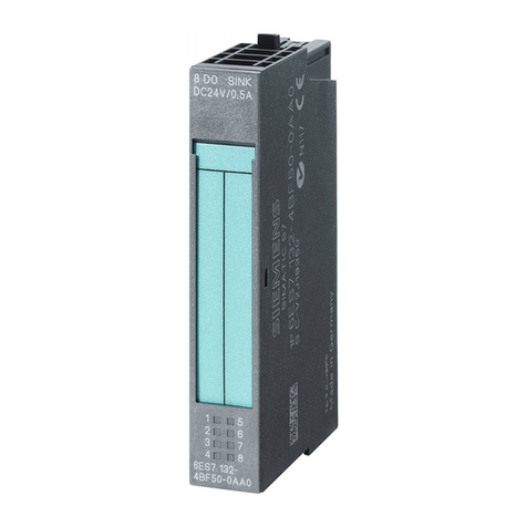
9.2.3.4 X111, X222 and X333 digital inputs/outputs.............................................................................105
9.2.4 Parameter assignment..............................................................................................................111
9.2.4.1 Input / output images.................................................................................................................111
9.2.4.2 Diagnostics via input image.......................................................................................................112
9.2.5 Technical data...........................................................................................................................113
9.3 PP 72/48D 2/2A PN...................................................................................................................114
9.3.1 Description................................................................................................................................114
9.3.2 Dimension drawing....................................................................................................................117
9.3.3 Mounting....................................................................................................................................117
9.3.4 Connection................................................................................................................................118
9.3.4.1 Interface overview.....................................................................................................................118
9.3.4.2 X1 power supply........................................................................................................................119
9.3.4.3 X2 PROFINET...........................................................................................................................121
9.3.4.4 X111, X222 and X333 digital inputs/outputs.............................................................................124
9.3.4.5 Analog X3 inputs/outputs..........................................................................................................130
9.3.5 Parameter assignment..............................................................................................................134
9.3.5.1 Input / output images.................................................................................................................134
9.3.5.2 Assigning parameters to the analog inputs / outputs................................................................136
9.3.5.3 Analog value representation......................................................................................................138
9.3.5.4 Examples...................................................................................................................................141
9.3.5.5 Diagnostics via input image.......................................................................................................142
9.3.6 Technical data...........................................................................................................................144
9.4 COM01.3 RS 232C (V.24) module............................................................................................145
9.4.1 Description................................................................................................................................145
9.4.2 Installation/Mounting.................................................................................................................147
9.4.3 Connection................................................................................................................................147
9.5 CBE30-2....................................................................................................................................148
9.5.1 Description................................................................................................................................148
9.5.2 Installation/Mounting.................................................................................................................151
9.5.3 Connection................................................................................................................................152
10 Spare Parts/Accessories..........................................................................................................................155
10.1 Replacing the dual fan/ battery module.....................................................................................155
10.2 CompactFlash Card..................................................................................................................157
10.2.1 Properties of the CompactFlash card........................................................................................157
10.2.2 Inserting the CompactFlash card..............................................................................................157
A Appendix...................................................................................................................................................159
A.1 Abbreviations.............................................................................................................................159
A.2 Documentation overview...........................................................................................................161
Index.........................................................................................................................................................163
Table of contents
NCU 7x0.3 PN, NCU 7x0.3B PN
Manual, 06/2014, 6FC5397-1EP40-5BA1 7
