Stealth Products CUSTOM Operation manual

FEATURES:
• Lateral and pre-ischial
shelf contoured, high-
density molded foam
base.
• Twin-cell, lightweight
uid insert under at risk
bony areas.
• CoolCore®technology
cover standard.
• 4-Way Stretch Poly liner
optional.
• Sizes available - 14”-
24”W x 16”-24”D
SPECTRUM GEL SPP
INSTALLATION AND CARE INSTRUCTIONS
CUSTOM

Stealth Products strives for 100% customer satisfaction. Your complete
satisfaction is important. Please contact us with feedback or suggested changes
to help improve the quality and usability of our products. You may reach us at:
General
Read and understand all instructions prior to the use of the product. Failure to
adhere to instructions and warnings in this document may result in property
damage, injury, or death. Product misuse due to failure to adhere to the following
instructions will void the warranty.
Immediately discontinue use if any function is compromised, if parts are missing
or loose, or if any component shows signs of excessive wear. Consult with your
supplier for repairs, adjustments, or replacements.
MDSS GmbH
Schigraben 41
30175 Hannover, Germany
Customer Satisfaction 1.0
Stealth Products, LLC
1 0 4 J o h n K e l l y D r i v e , B u r n e t , T X 7 8 6 1 1
Phone: (512) 715-9995 Toll Free: (800) 965-9229
Fax: (512) 715-9954 Toll Free: (800) 806-1225
[email protected] www.stealthproducts.com
i

Important Information!
All persons responsible for tting, adjustment, and daily use of the devices
discussed in these instructions must be familiar with and understand all safety
aspects of the devices mentioned. In order for our products to be used
succesfully, you must:
•read and understand all instrucons and warnings;
•maintain our products according to our instrucons on care and maintenance; and
• ensure devices are installed and adjusted by a trained technician.
Supplier Reference
Supplier:
Telephone:
Address:
Purchase Date:
Model:
Important Information 2.0
ii

These installation instructions will guide you through your product’s options
and possibilities. They are written with the expressed intent of use with standard
congurations. They also contain important safety and maintenance information
and describe possible problems that may arise during use. For further assistance
or more advanced applications, please contact your supplier or Stealth Products,
LLC at (512) 715-9995 or toll free at (800) 965-9229.
Always keep the operating instructions in a safe place so they may be referenced
as necessary.
All information, pictures, illustrations, and specications are based on the product
information that was available at the time of printing. Pictures and illustrations
shown in these instructions are representative examples and are not intended to
be exact depictions of the various parts of the product.
Ordering Documentation
You can download additional copies of this user manual by accessing the
Stealth website (https://stlpro.site/stealth-docs) and searching “Custom Cushion
Owner’s Manual” in the search bar at the top of the page.
Introduction 3.0
iii
CAUTION
These products are designed to be tted, applied, and installed exclusively by a
healthcare professional trained for these purposes. The tting, application and
installation by a non-qualied individual could result in serious injury.

Warranty 4.0
Our products are designed, manufactured, and produced to the highest of
standards. If any defect in material or workmanship is found, Stealth Products,
LLC will repair or replace the product at our discretion. Any implied warranty,
including the implied warranties of merchantability and tness for a particular
purpose, shall not extend beyond the duration of this warranty. Stealth
Products, LLC does not warrant damage due to, but not limited to:
•misuse, abuse, or misapplicaon of products; and/or
•modicaon of products without wrien approval from Stealth Products, LLC.
Any lack or alteration of serial number, where applicable, will automatically void
this warranty.
Stealth Products, LLC is liable for replacement parts only. Stealth Products, LLC is
not liable for any incurred labor costs.
No person is authorized to alter, extend, or waive the warranties of Stealth
Products, LLC.
Stealth Products warrants against failure due to defective materials or
workmanship for a period of:
Covers/Soft Goods: 2 years
Hardware: 5 years
Electronics: 3 years
In Case of Product Failure
In the event of product failure covered by our warranty, please follow the
procedures outlined below:
1. Call Stealth Products at (512) 715-9995 or toll free at (800) 965-9229.
2. Request a Return Authorizaon form (RA) from the Returns Department and follow the
instrucons on the document.
iv

Table of Contents 5.0
v
.
1.0 Customer Satisfaction ................................................................................. i
2.0 Important Information............................................................................... ii
3.0 Introduction ............................................................................................... iii
4.0 Warranty ..................................................................................................... iv
5.0 Table of Contents........................................................................................ v
6.0 Warning Labels.......................................................................................... vii
6.1 Warning Labels ...........................................................................................................vii
6.2 Limited Liability...........................................................................................................vii
7.0 Design and Function................................................................................... 1
7.1 Intended Use .................................................................................................................1
7.2 Features ...........................................................................................................................1
8.0 Installation Instructions ............................................................................. 2
8.1 Preparations...................................................................................................................3
8.2 Tools..................................................................................................................................3
8.3 Installation Plan ............................................................................................................3
8.4 Required Tools...............................................................................................................4
8.5 Hardware System Assemblies .................................................................................5
8.6 Hardware System Installation..................................................................................6
9.0 WC20 Information .................................................................................... 13
9.1 WC20 All-Purpose Hardware................................................................................13
9.2 Before Transit.............................................................................................................. 13
9.3 Belt Placement ...........................................................................................................14
9.4 User Safety...................................................................................................................17

Table of Contents 5.0
vi
10.0 First-Time Use .........................................................................................19
10.1 Dealer Assistance ................................................................................................... 19
10.2 User Testing ..............................................................................................................19
10.3 Conditions of Use................................................................................................... 19
11.0 Maintenance........................................................................................... 20
11.1 Cleaning .....................................................................................................................20
11.2 Disinfecting............................................................................................................... 20
11.3 Maintenance............................................................................................................. 21
12.0 Notes....................................................................................................... 22

Warning Labels 6.0
Warning Labels 6.1
Warnings are included for the safety of the user, client, operator and property.
Please read and understand what the signal words DANGER, WARNING,
CAUTION, NOTICE and SAFETY mean, and how they could aect the user, those
around the user, and property.
Limited Liability 6.2
Stealth Products, LLC accepts no liability for personal injury or damage to
property that may arise from the failure of the user or other persons to follow
the recommendations, warnings, and instructions in this manual.
Stealth Products, LLC does not hold responsibility for nal integration or nal
assembly of product to end user. Stealth Products, LLC is not liable for user death
or injury.
DANGER Identies an imminent situation which, if not avoided, may
result in severe injury, death, and/or property damage.
WARNING Identies a potential situation which, if not avoided, may
result in severe injury, death, and/or property damage.
CAUTION
Identies a potential situation which, if not avoided, may
result in minor to moderate injury, and/or property
damage.
NOTICE
Identies important information not related to injury, but
possible property damage.
SAFETY
Indicates steps or instructions for safe practices, reminders
of safe procedures, or important safety equipment that may
be neccesary.
vii

Design and Function 7.0
1
Features 7.2
The Custom Cushion features numerous customizable options and
accommodations to provide the best t for each user. Customizable options
include:
• Frame Width and Seat Depth
•Cover Material
•Cushion Shape
•Cushion Base
• Growth Notches
• Hamstring Relief Depth
•Leg Length Discrepancy Cuts
• Anti-Thrust
• Abduction and Adduction Options
•Cushion Foam Composition
• Ischial Gel Inserts
•Accessories (Zippered Pouch, Extra Cover, Incontinence Liner)
Intended Use 7.1
Stealth Products’ Custom Cushion is designed to provide optimal tting for
individuals requiring solid seats to support minimal deformities or stability
needs, and who require moderate postural support, improved trunk or pelvic
positioning, or have mild pelvic asymmetries.

Installation Instructions

Installation Instructions 8.0
3
Preparations 8.1
Only a qualied service technician may install the Custom Cushion and its
accessories.
WARNING
Incorrect installation of the Custom Cushion or its accessories may cause
damage to the hardware and/or injury to the user.
Tools 8.2
Use the proper tools to install and adjust the Custom Cushion to the desired
position for the user.
Installation Plan 8.3
Set up an installation plan before beginning the installation. This plan should take
into account:
• where the Custom Cushion will be placed;
• how the Custom Cushion will be operated, including the release funcons for the hardware
opons; and
• a sucient amount of clearance for other hardware and accessories.
CAUTION
The use of improper tools may cause damage to the device.
CAUTION
Any connection must always be secured with all delivered screws. Only use the
screws provided in the package.
Installation Instructions 8.0
4
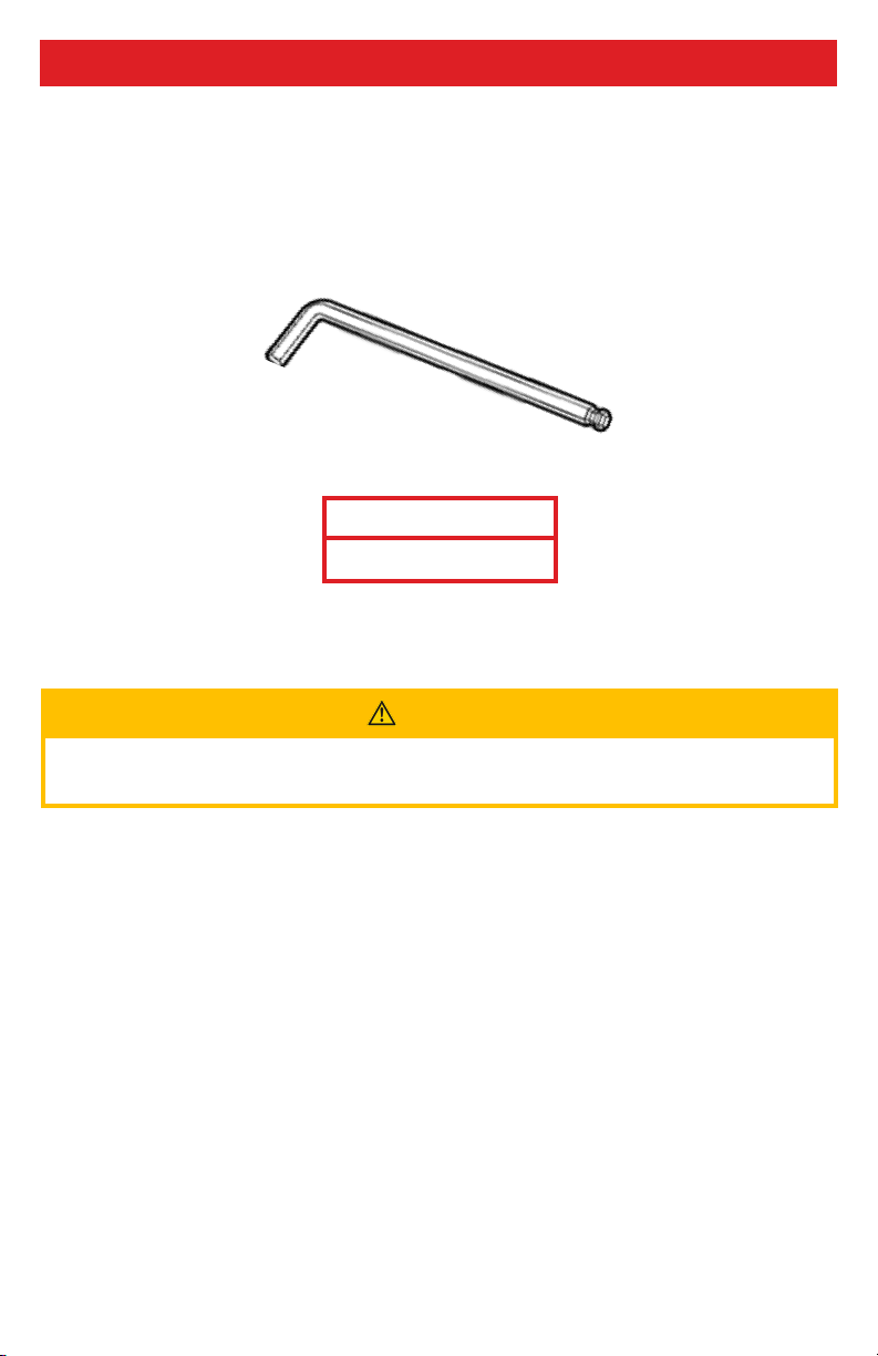
Required Tools 8.4
Below are the tools needed to complete the installation of the cushion hardware
systems:
Tools are not provided. Refer to the manuals provided with additional accessories
for a list of the tools required to install those accessories.
Tool:
5/32” Hex Key
CAUTION
Tools required to install additional accessories are detailed in the manuals for
those accessories.

Installation Instructions 8.0
5
Hardware System Assemblies 8.5
J&L Hardware:
Trouble Free Hardware:
All-Purpose Hardware:
(Note: Two-point assemblies pictured.)
When coupled with a seat pan, the Custom Cushion is able to be installed on
wheelchairs via three dierent hardware options. Each hardware option can be
ordered to t on 3/4”, 7/8”, or 1” wheelchair canes.
Hold Down Drop
Stop Weldments
Female/Male Tube
Stop Clamps
All-Purpose Knob
Clamps
Transit Locking
Pins
(Note: Four-point
J&L hardware
assemblies will
include two rotang
weldments, to be
ouied at the back
of the chair.)
Rotang Hold
Down Drop Stop
Weldments
(Note: Four-point
All-Purpose hardware
assemblies will include
four WC20-labeled
locking pins.)
Installation Instructions 8.0
6
Hardware System Installation 8.6
This section details how to install the cushion to the wheelchair with the three
available hardware congurations.
Please note that the hardware is functional whether it faces outward (as is
pictured) or inward. The amount of space, clearance, and the type of chair are the
determining factors in installation compatibility.
J&L Hardware Installation:
The J&L hardware attaches to a wheelchair in two-point or four-point options.
The following instructions are for the two-point option. In order to install the
four-point option, simply repeat the following steps for the two remaining
hardware sub-assemblies.
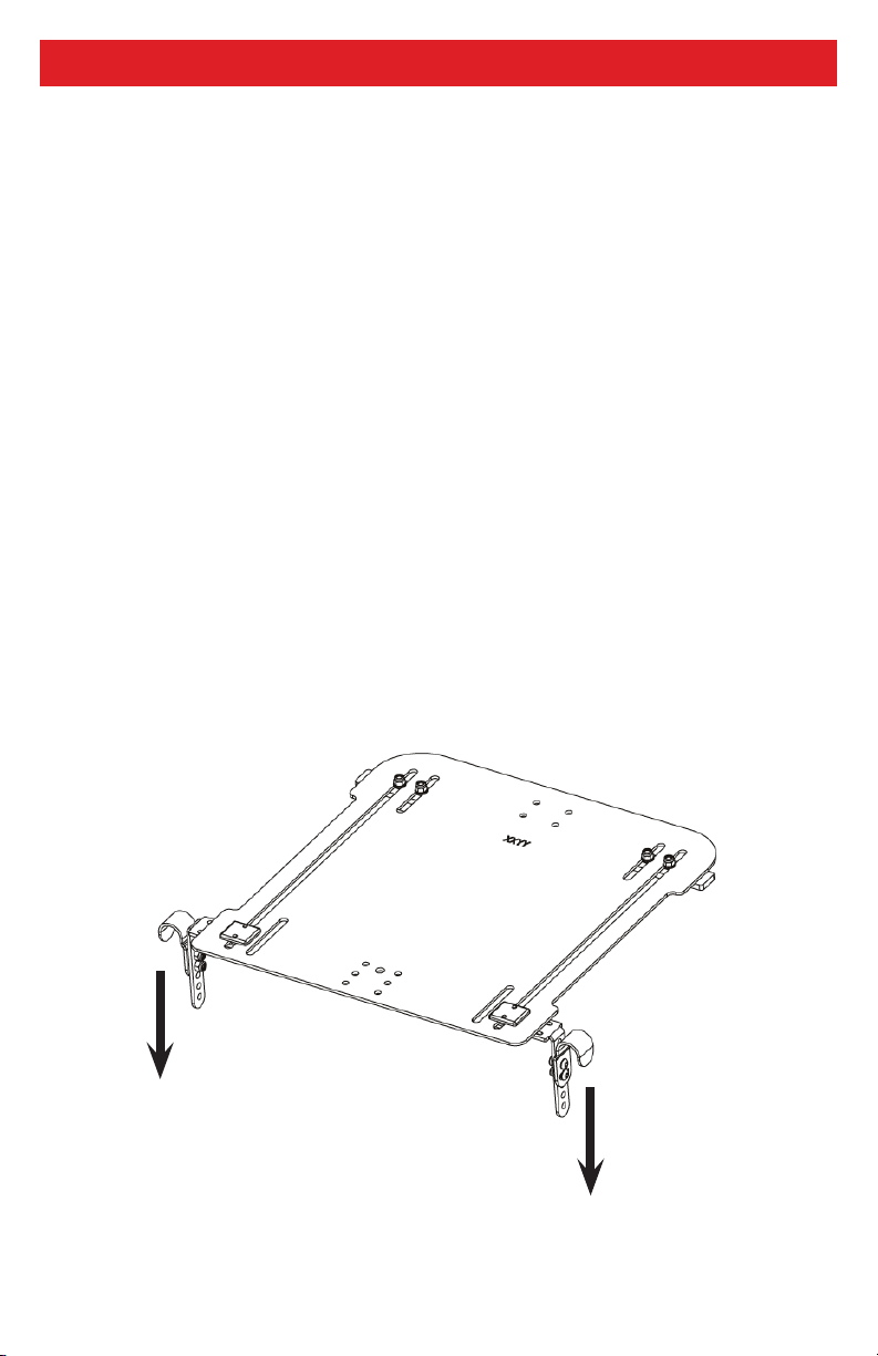
Step One: Place the seat pan assembly onto the wheelchair canes so that the
hardware is at the front of the chair.
Front
Back

Installation Instructions 8.0
7
Step Two: Using a 5/32” hex key, remove the screws, washers, and nuts from the Hold
Down Drop Stop Weldments. Position the weldments just outside the J-clips on the
wheelchair cane.
Step Three: Use the 5/32” hex key to replace the screws, washers, and nuts from the
weldments and tighten rmly.

Installation Instructions 8.0
8
Trouble Free Hardware Installation:
The Trouble Free hardware attaches to a wheelchair in two-point or four-point
options. The following instructions are for the two-point option. In order to
install the four-point option, simply repeat the following steps for the two
remaining hardware sub-assemblies.
Step One: Unlatch the clasps of the hardware attached to the seat pan, then place the
seat pan assembly onto the wheelchair canes so that the hardware is at the front of
the chair. When the seat pan is in position, re-latch the clasps.
Front
Back

Installation Instructions 8.0
9
Step Two: Join the Female/Male Tube Stop Clamps around the wheelchair canes.
When the clamps are positioned
correctly, use a 5/32” hex key to
tighten the screws through the tube
stop clamps.

Installation Instructions 8.0
10
All-Purpose Hardware Installation:
The All-Purpose hardware attaches to a wheelchair in a two-point or a WC20-
approved four-point option. The following instructions are for the four-point
option.
Step One: Using a 5/32” hex key, slightly loosen the three screws in the base of each
knob’s clamp, pictured below.
Step Two: With the clamp screws now loosened, slide the clamps onto the wheelchair
canes.
Determine an ideal position for each
knob assembly, then tighten down
the clamp screws to secure it in place.

Installation Instructions 8.0
11
Step Three: Turn the knobs counterclockwise to loosen them and expose the knob’s
center screw.
Step Four: Place the seat pan assembly onto the knob assembly. Ensure the seat’s
L-brackets are ush with the knobs’ exposed center screws.

Installation Instructions 8.0
12
Step Five: Turn the knobs clockwise to rmly tighten them against the L-brackets.
Step Six: In order to comply with the provisions and requirements of WC20, the
provided locking pins must be inserted in the through-holes of each L-bracket, as
illustrated below.
Table of contents


