STEAM Train STEAMbot V1.3 User manual

STEAMbot V1.3 User Guide, Rev 2
2018 © Copyright The STEAM Train 1
STEAMbot V1.3 User Guide
Introduction
Welcome to the world of STEAMbot robots! We at The STEAM Train want to thank you for getting a
STEAMbot robot kit. We believe that any child that wants a robot should be able to afford one. This
kit will help you learn more about Science, Technology, Engineering, Art and Math (STEAM). We
hope you will have lots of fun putting your robot together and learning how to program it. Your
efforts will be rewarded and give you opportunities for a better future.
This guide has the following chapters:
1. Assembly of Your STEAMbot –covers how to assemble your STEAMbot robot.
2. STEAMbot Controller –provides a description of the STEAMbot Controller, the heart of you
robot.
3. Software Installation –tells you how to install the required software so you can program your
STEAMbot robot.
Warning
Although the STEAMbot has been carefully designed and manufactured, the STEAMbot has fragile
components. Dropping it or pushing on the Ultrasonic Sensor Bracket may cause it to crack or break.
In addition, the header pins of the STEAMbot Controller can pierce your skin if you are not careful.
The pins are also easy to bend. So please handle your STEAMbot with care.
Glossary
The following terms are used in this document.
STEAMbot V1.3 User Guide, Rev 2
2018 © Copyright The STEAM Train 2
Term
Meaning
BLE
Bluetooth Low Energy or Bluetooth 4.0
PCB
Printed Circuit Board
USS
Ultrasonic Sensor
Assembly of Your STEAMbot
Parts
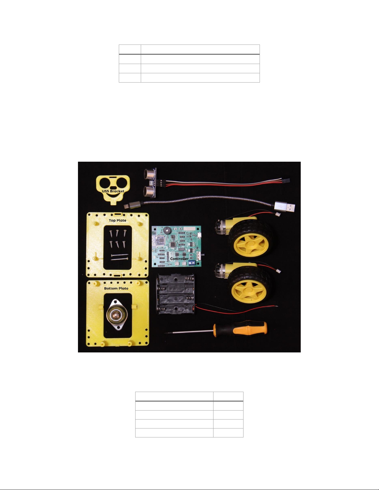
Figure 1 shows you all the parts that should be in your kit. If any part is missing, please email us at
support@thesteamtrain.cc.
Figure 1, STEAMbot Kit Parts
The following table has the parts and quantities.
Part
Quantity
STEAMbot Top Plate
1
STEAMbot Bottom Plate
1
STEAMbot Controller
1
DC Motor and Wheel
2
STEAMbot V1.3 User Guide, Rev 2
2018 © Copyright The STEAM Train 3
Part
Quantity
Battery Holder
1
Ball Caster
1
Phillips Screwdriver
1
#4 1 inch screw
2
#4 3/8 inch screw
6 (or 8)
Ultrasonic Sensor and Wire
1
Ultrasonic Sensor Bracket
2
USB Cable
1
Note 1: the wire on the USS
Note 2: the USS Bracket shown is one of several that are available. When you placed the order for
your STEAMbot, you had the option to pick two different brackets.
Parts Not Included
The following parts are needed but not supplied in the kit:
•Four AA batteries –please read the section on batteries on page 11.
•A smart phone with Bluetooth LE support. This is optional if you want to remotely control
your STEAMbot.
•A small flat screwdriver. In the near future this screwdriver will not be required.
•A Windows or MacOS computer. Needed only if you want to program the STEAMbot using
either the Arduino IDE or Google’s Blockly.
Assembly Steps
It is highly recommended that you read through all the steps below and then perform the following
steps to assemble your STEAMbot:
1. If the wheels are attached to the motors, remove the wheels by pulling them from the motor. The
wheels fit tightly so be careful when pulling on the wheel to not break the axel.
2. Place the bottom plate flat on a table along with both motors and the two 1” screws, as shown in
Figure 2.

STEAMbot V1.3 User Guide, Rev 2
2018 © Copyright The STEAM Train 4
Figure 2, Bottom Plate with Motors
3. Use a 1” screw to attach each motor to the bottom plate. Be careful not to strip the plastic as you
tighten.
4. Place the top plate over the bottom. Screw the top plate to the bottom plate using four 3/8”
screws as shown in the following figure.
Figure 3, Top Plate
5. Flip the robot. Using two 3/8” screws, attach the roller ball to the bottom plate as shown in the
following figure.

STEAMbot V1.3 User Guide, Rev 2
2018 © Copyright The STEAM Train 5
6. Take the wheels and attach them to the motors.
7. Flip the robot over so it is resting on the wheels and roller ball as shown in the following figure.
Figure 4, Chassis with Wheels
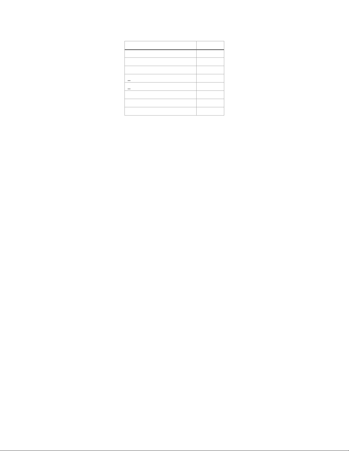
8. Add 4 AA batteries to the battery holder.
9. Place the battery holder on the top plate as shown in the following figure.
STEAMbot V1.3 User Guide, Rev 2
2018 © Copyright The STEAM Train 6
Figure 5, Battery Holder
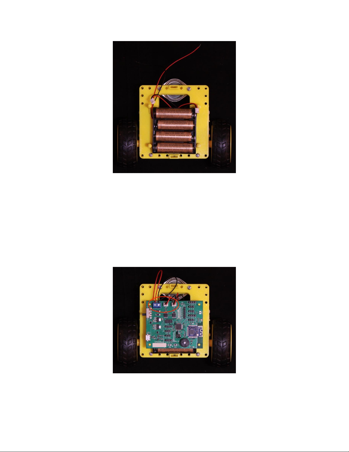
10. Take the STEAMbot Controller and place it on the posts of the top plate. Note that some version
may have two posts and two screw holes. If you have the screw holes, screw in the last two 3/8”
screws to hold the STEAMbot Controller in place.
11. Loosen the screws of the blue battery terminal, labeled “+BATT-”with the small flat screwdriver.
12. Insert the red wire from the battery holder to the + battery terminal and tighten the screw.
13. Insert the black wire from the battery holder to the - battery terminal and tighten the screw.
14. Push the wire from the left motor onto the JST connector labeled “MTRA”.
15. Push the wire from the right motor onto the JST connector labeled “MTRB”.
16. Make sure the wiring is as shown in the following figure.
Figure 6, STEAMbot Controller
17. Pick an ultrasonic sensor bracket. As stated above, you received at least two different brackets
when your STEAMbot was ordered.
STEAMbot V1.3 User Guide, Rev 2
2018 © Copyright The STEAM Train 7
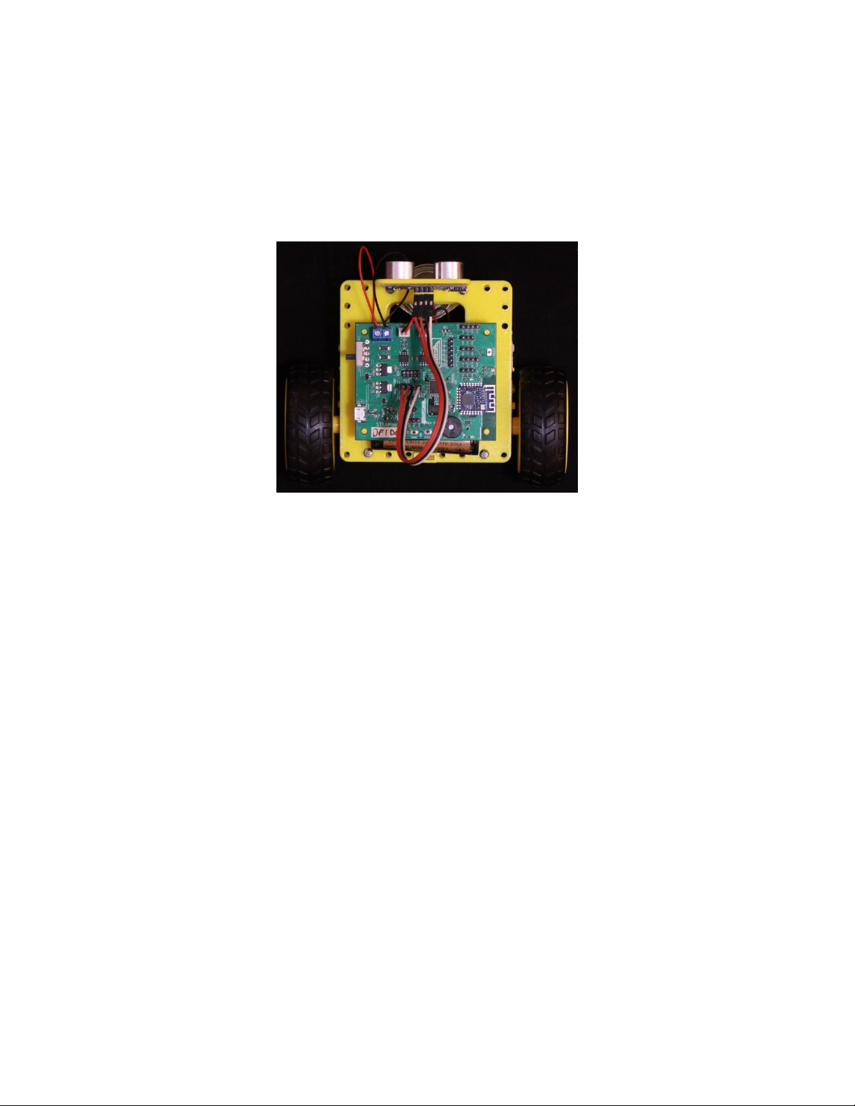
18. Take the ultrasonic sensor (with the attached four conductor wire), align it with the holes on the
ultrasonic sensor bracket and press fit the sensor into the bracket. The wire goes to the top.
19. Take the other end of the wire from the ultrasonic sensor and plug each conductor into the pins
labeled “P5”. Note that the colors of the four-conductor wire differ between kits. The important
thing to remember is to keep them in the same order on the sensor as on the pins of P5. Your
robot should look similar to the following figure.
20. Push the power switch to the ON position (labeled on the PCB). A red LED near the speaker on
the STEAMbot controller will turn red. The LED near the RESET button will blink green for
about 1 second. You will hear a beep; the LED will turn several colors and then stay blue.
21. Congratulations, your STEAMbot is ready to be controlled via a smart phone (iPhone or Android)
or to be programmed by you! If you don’t have a smart phone, see below for the different modes.
Now go have some fun with your STEAMbot robot!
Where Is the Front of The STEAMbot?
If you correctly followed the assembly steps above, the front of your STEAMbot is where the is
where the ball caster is. However, if you wish to flip this configuration so that the ball caster is the
rear, just swap to which motor terminal blocks the wires from the motors are connected, i.e. push the
wire from the left motor onto the JST connector labeled “MTRB” and push the wire from the right
motor onto the JST connector labeled “MTRA”.
Batteries
The STEAMbot robot has been tested with alkaline batteries and with Ni-Zn rechargeable batteries.
The STEAMbot does NOT support Ni-Cd or Ni-MH rechargeable batteries. These batteries only
provide 1.2 volts each as compared to the 1.5 volts produced by alkaline batteries or the 1.6 volts
provided by Ni-Zn batteries. Four Ni-Cd or Ni-MH provide only 4.8 volts which is not enough to
reliably power the STEAMbot.
Figure 7, Completed STEAMbot

STEAMbot V1.3 User Guide, Rev 2
2018 © Copyright The STEAM Train 8
An alternative to AA batteries is to use a USB Power Bank that are commonly available. These are
rechargeable and can be used multiple times. The power bank comes with a USB cable that is
connected to the USB connector on the STEAMbot Controller. The downside to using a power bank
is that the power switch is bypassed. To turn off your STEAMbot, remove the USB cable.
Removing or Adding Batteries
To remove or add batteries from the battery holder, carefully remove the STEAMbot Controller from
the mounting posts. It’s best to use a thumb and push up with the thumbnail. If the STEAMbot
Controller was held in place with screws, first remove the screws and then push up the STEAMbot
Controller from the two posts using your thumbs.
Modes
The default program that comes with the STEAMbot robot provides the following two modes:
1. Bluetooth mode –in this mode, the STEAMbot is controlled by a smartphone using the built-
in Bluetooth LE module. When first powered on or after a reset, this is the mode the
STEAMbot is in.
2. Cat mode –in this mode, the STEAMbot acts similar to a cat. Put an object in front of the
STEAMbot (your hand, your shoe, a broom or something similar). At a certain distance, the
STEAMbot will follow the object. However, if the STEAMbot gets too close to the object, it
will back away from the object.
To change modes, push both the RUN and the STOP button. You will hear a single beep when
transitioning from Cat mode to Bluetooth mode. You will hear a beep and then a higher pitched beep
when transitioning from Bluetooth mode to Cat mode.
Programming Your STEAMbot
Google’s Blockly
The easiest way to program your STEAMbot is with Google’s Blockly. Blockly is a “block
programming” language, very similar to MIT’s Scratch. To you program with Blockly, you must have
one of the following setups:
•A ChromeBook with BLE support
•A Macintosh (Mac) computer with BLE support and running Google’s Chrome web browser
Using one of the setups above, start your Chrome browser and go to https://thesteamtrain.cc/sbp.
When the page loads, along the top you will see a “Connect to” button next to a shaded “STEAMbot-”
label and then a greyed out “ID” field. In this field, enter the alphanumeric information written on
the STEAMbot Controller under “STEAMbot”. Turn on your STEAMbot and click the “Connect to”
button.

STEAMbot V1.3 User Guide, Rev 2
2018 © Copyright The STEAM Train 9
See the highlighted figure below.
Figure 8, STEAMbot ID
A Blockly Programming Guide will be available soon.
Software Installation for Arduino IDE
You can program your STEAMbot with the Arduino Integrated Development Environment (IDE) and
some additional software and libraries. You must know C/C++ in order to program your STEAMbot.
In the near future, you will be able to program your STEAMbot with a drag-and-drop programming
environment such as Scratch or other similar environment.
Please follow the following steps to install all the required software:
1. On Windows, install the software from the Microsoft Store. On a Mac, download the Arduino
IDE from https://www.arduino.cc/en/Main/Software. Refer to the
https://www.arduino.cc/en/Guide/HomePage for the instructions on how to install the software.
2. Start the Arduino IDE. Open up the Preferences dialog. On Windows it’s under File →
Preferences.
3. In the text field for Additional Boards Manager URLs enter
“http://dan.drown.org/stm32duino/package_STM32duino_index.json”. Click the OK button.
4. Click on Tools →Board →Boards Manager. When the Board Manager dialog box appears, enter
“maple” into the “Filter your search...” text box.
5. Select the “STM32Fxx/GD32F1xx boards by stm32duino” option and click “Install”.
6. The installation process may take several minutes. When completed, click “Close”.
STEAMbot V1.3 User Guide, Rev 2
2018 © Copyright The STEAM Train 10
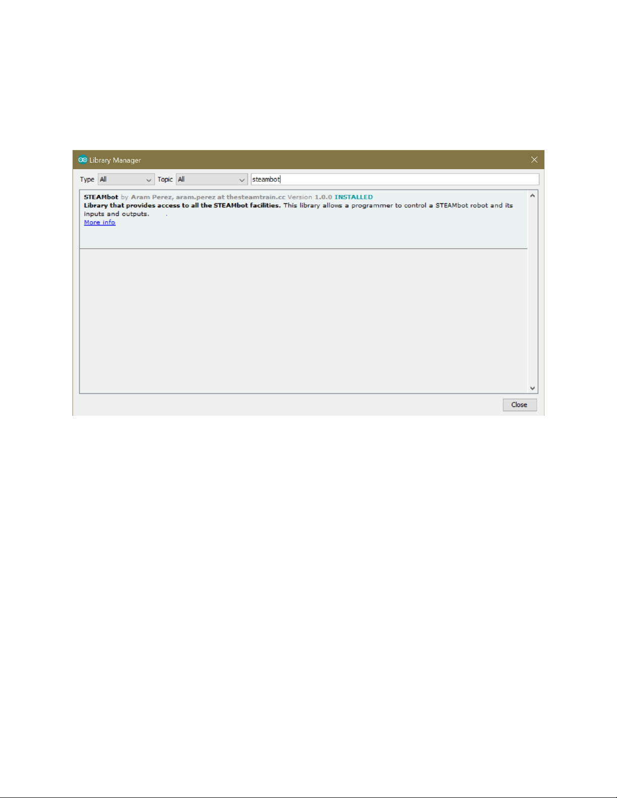
7. Click on Sketch →Include Library →Manage Libraries...
8. When the Library Manager dialog appears, enter "steambot" into the "Filter your search..." text
field. Select the STEAMbot library and click install. Note that the version may be a later version.
It will take a few seconds to install the library and you should see the following.
9. Click the Close button (see figure below).
10. Click on Tools →Board: and select "Maple Mini".
11. Click on Tools →Bootloader Version and select "Bootloader 2.0 (20k RAM, 120k Flash)".
12. On Windows, click on Tools →Port and select the COM port which has "(Maple Mini)" after it.
13. You can now look at the different examples we provide by selecting File →Examples →
STEAMbot, including the DefaultSTEAMbot example which is the default program running
when you first get your STEAMbot and power it up.
14. You are now ready to create your very own programs your STEAMbot to do other things! And
please share them on our web site.
STEAMbot Controller
The STEAMbot is controlled by a controller board that provides all the required functions to control
the robot but also allows you to expand your robot by adding additional sensor and/or actuators. It
can easily be programmed by the Arduino IDE (see the next chapter). It has a 32-bit
STM32F103CBT6 ARM microcontroller with 128 KB FLASH memory (to store your programs), 20
KB of RAM (used while running your program to store data that changes) and 17 general purpose
Figure 9, Arduino Library Manager

STEAMbot V1.3 User Guide, Rev 2
2018 © Copyright The STEAM Train 11
inputs and outputs (GPIOs). There are two GPIO that are assigned to the Ultrasonic Sensor that
comes with the kit.
The following functionality is built into the controller:
•An RGB LED that supports 8 different colors.
•A speaker that can produce a variety of different notes and beeps.
•Two H-bridge controllers for controlling 2 DC motors.
•A Bluetooth LE module for communications with external devices such as smart phones.
•Two pushbuttons that can be used by programs you write.
General Purpose Input and Outputs
All the GPIOs are available on male pin headers, grouped in different connectors. Each connector has
power and ground to make it easy to connect sensors and actuators. The following table lists the
header and pins.
Table 2, Pin Headers
Header
Pin 1
Pin 2
Pin 3
Pin 4
Pin 5
Pin 6
P5*
+5V
PA14
PA13
GND
-
-
P6
PB6 (SRV2)
+5V
GND
-
-
-
P7
PB7 (SRV1)
+5V
GND
-
-
-
Figure 10, STEAMbot Controller

STEAMbot V1.3 User Guide, Rev 2
2018 © Copyright The STEAM Train 12
P8
+5V
PB7
PB6
GND
-
-
P9
PWR**
PB15/MOSI2
PB14/MISO2
PB13/SCK2
PB12/SS2
GND
P10
PWR**
PA10/RX1
PA9/TX1
GND
-
-
P11
PA8
PWR**
GND
-
-
-
P12
PB5
3.3V
GND
-
-
-
P13
3.3V
PA11/RX3
PB10/TX3
GND
-
-
P14
PB2
3.3V
GND
-
-
-
* The default STEAMbot program expects the Ultrasonic Sensor to be connected on P5. If you write
your own program and will not need the Ultrasonic Sensor, you can use the GPIO pins on P5.
** Default PWR is 5V but can be changed to 3.3V by cutting trace of JP1 to 5V and soldering wire to
3.3V (labeled “3V” on the board).
JTAG
The Controller board also has a JTAG connector (P4) that is useful for low level debugging. Very few
persons will need to use this connector. The following table provides the pinouts.
Table 3, JTAG
Pin
Signal
Pin
Signal
1
3.3V
2
PA13/JTMS
3
GND
4
PA14/JTCK
5
PB4/NJTRST
6
PB3/JTD0
7
GND
8
PA15/JTDI
9
GND
10
NRST
This table is provided for completeness and can generally be ignored.
Table of contents
Other STEAM Train Toy manuals


Popular Toy manuals by other brands

MinimumRC
MinimumRC Beech V-35 Install manual

Oregon Scientific
Oregon Scientific Electronic Learning Aid Tote N' Teach instruction manual

Faller
Faller ST. MARTIN'S GATE IN FREIBURG I. BR. Assembly instructions

Mega Bloks
Mega Bloks Barbie Build'n Play Fab Park manual

Fisher-Price
Fisher-Price RAINFOREST K4562 instruction sheet

marklin
marklin 37104 user manual


