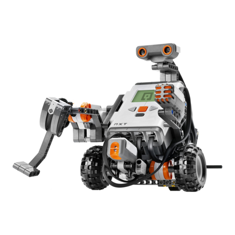
STEAM Train STEAMbot V2.0 User manual

STEAMbot V2.0 User Guide, Rev 0
2020 © Copyright The STEAM Train 1
STEAMbot V2.0 User Guide
Introduction
Welcome to the world of STEAMbot robot kits! We at The STEAM Train want to thank you for
getting a STEAMbot robot kit. We believe that any child that wants a robot should be able to get
one, no matter their socio-economic background. This kit will help you learn more about
Science, Technology, Engineering, Art, and Math (STEAM). We hope you will have lots of fun
putting your robot together and learning how to program it. Your efforts will be rewarded and
give you opportunities for a better future.
This guide has the following chapters:
1. Assembly of Your STEAMbot –provides the steps of how to assemble your STEAMbot
robot.
2. Connectivity –describes how the STEAMbot communicates over a WiFi network.
3. STEAMbot Home Page –describes the home page of the STEAMbot. Via the home page
you can control your STEAMbot, change the operating modes of your STEAMbot, ,
mange the WiFi networks it connects to, calibrate the motors of your STEAMbot, update
the firmware of your STEAMbot and finally, you can program your STEAMbot.
Why Robotics?
When you learn about robotics, you will learn about the following fields:
•Mechanical engineering –how is the robot designed to mechanically work together and
make sure all the parts fit and not fall apart.

STEAMbot V2.0 User Guide, Rev 0
2020 © Copyright The STEAM Train 2
•Electrical engineering –most robots use some sort of electricity to function. In addition,
when you connect a sensor or actuator, you must make sure it is connected electrically
correct. Otherwise, the sensor or actuator will not work.
•Computer science –A general purpose robot can perform different functions or tasks.
You will learn how to write programs to make the robot perform the different functions
or tasks.
Warning
Although the STEAMbot has been carefully designed and manufactured, the STEAMbot has
fragile components. Dropping it or pushing on the Ultrasonic Sensor Bracket may cause it to
crack or break. In addition, the header pins of the STEAMbot Controller can pierce your skin if
you are not careful. The pins are also easy to bend. So please handle your STEAMbot with care.
Documentation Updates
Although every attempt has been made to ensure that this document is correct, we are not
perfect. Be sure to periodically check our web site for updates to this document.
Glossary
The following terms are used in this document.
Table 1, Glossary
Term
Meaning
WiFi
Wireless communications network
AP
WiFi Access Point
DC
Direct Current
Device
Either a computer or a mobile device used to connect to a STEAMbot
Firmware
Software that runs on your STEAMbot and can be remotely updated
LED
Light Emitting Diode
PCB
Printed Circuit Board
STA
WiFi Station
USS
Ultrasonic Sensor
Vin
Voltage input, the same as VIN.
VIN
Voltage Input, the same as Vin
Identity
Each STEAMbot robot has its own unique identifier (or ID). The ID consists of the phrase
“STEAMbot-”followed by a 6-digit hexadecimal number. The 6-digit number should be taped
onto the top of the controller.

STEAMbot V2.0 User Guide, Rev 0
2020 © Copyright The STEAM Train 3
Web Server
When powered on, your STEAMbot robot runs a web server. All you need to control or program
your STEAMbot is a WiFi-enabled device that runs modern web browser.
Clicking
In this document, the term “click” is used throughout. It applies to devices where you use a
mouse to move a cursor to an object and your press the left button
1
of the mouse. If you are using
a device with a touch screen, you will tap the object instead of clicking it.
Batteries
Your STEAMbot robot requires batteries for power. The kit comes with a holder for four AA
batteries. The following table lists the different types of AA batteries along with their pros and
cons.
Table 2, AA Size Batteries
Type
Voltage
Total
Voltage
Pros
Cons
Regular
(non-
alkaline)
1.5V
6V
Lowest initial cost
Lowest capacity, cannot be
recharged.
Alkaline
1.5V
6V
Higher capacity than regular
Higher cost than regular,
cannot be recharged.
Ni-Cd
1.2V
4.8V
Rechargeable, lowest cost
rechargeable, good capacity
Suffers from “memory”
issue, a smaller number of
recharges, higher initial
cost than regular/alkaline
Ni-MH
1.2V
4.8V
Large number of recharges,
medium cost rechargeable, very
good capacity
Higher initial cost.
Ni-Zn
1.6V
6.4V
Higher voltage
High initial cost, lower
capacity than Ni-CD or
MH.
Li-ion
3.7V
7.4V
Highest voltage, needs only two
batteries, very good capacity
Highest initial cost,
requires a different battery
holder.
The following table lists alternatives to using AA sized batteries.
1
Unless you have changed the normal behavior for mouse buttons.

STEAMbot V2.0 User Guide, Rev 0
2020 © Copyright The STEAM Train 4
Table 3, Alternative Batteries
Type
Total
Voltage
Pros
Cons
9 Volt
9V
Only one battery needed
Low capacity, cannot be
recharged.
Rechargeable
9 Volt
9V
Only one battery needed
Higher cost than regular 9-volt,
low capacity.
USB Power
Bank
5V
Large number of recharges,
good capacity
Relative high cost, special USB
cable is required.
The electronics of your STEAMbot robot uses 3.3V. All the batteries (except for the USB Power
Bank) must be connected to the VIN/GND terminal posts. The voltage on the VIN terminal is
connected to a voltage regulator which regulates the voltage down to 3.3V. The maximum
voltage that can be applied to the VIN terminal is 10V. Exceeding this voltage will damage the
electronics!
A USB power bank can be connected via a special cable to the VIN/GND terminal posts or via a
micro USB cable. The disadvantage of the USB cable is that you have to plug in the cable to the
controller board to turn on the STEAMbot or remove the cable to turn it off. You can find right
angle micro USB cables which make it a little bit easier.
Normally the motors are driven from the voltage applied to the VIN terminal. The higher the
voltage on the VIN terminal, the faster your STEAMbot will move. The exception is if a USB
cable is connected to the controller in which case the motors run from the USB voltage (normally
5V). In all cases, as the voltage of the batteries
Assembly of Your STEAMbot
Parts
Figure 1 shows you all the major parts that should be in your kit apart from the chassis. The
chassis and screws are listed separately. If any part is missing, please email us at

STEAMbot V2.0 User Guide, Rev 0
2020 © Copyright The STEAM Train 5
Figure 1, STEAMbot Robot Kit Parts
The following table lists the parts of the kit (except for the chassis and screws).
Table 4, STEAMbot Parts List
Number
Name
Quantity
1
USS Bracket (see note below)
1
2
Ultrasonic Sensor
1
3
Speaker
1
4
Controller
1
5
Batter Holder
1
6
Wheels
2
7
Roller Ball
1
8
DC Motors
2
Note: The shape of the USS Bracket may be different, depending on what you ordered.
The STEAMbot chassis is laser cut from birch plywood. The chassis parts should be in a plastic
bag. Figure 2 shows all the parts of the chassis.

STEAMbot V2.0 User Guide, Rev 0
2020 © Copyright The STEAM Train 6
Figure 2, STEAMbot Chassis

STEAMbot V2.0 User Guide, Rev 0
2020 © Copyright The STEAM Train 7
The following table lists the parts of the chassis.
Table 5, STEAMbot Chassis Parts List
Number
Name
1
Left Motor Mount
2
Bottom Plate
3
Right Motor Mount
4
Back Wall
5
Top Plate
6
Left Support
7
Right Support
8
USS Support
9
Left Wall
10
Right Wall
11
Bottom Cover
12
Top Cover
Finally, there is a small plastic bag with six #4 machine screws. There should be two 1-inch
screws and four 3/8-inch screws.
Parts Not Included
The following parts are needed but are not included in the kit:
•Four AA batteries –please read the section on batteries on page 3.
•Optional: A mobile device with WiFi and a modern web browser. It is required only if
you want to remotely control your STEAMbot. If the mobile device is a tablet, you will
also be able to program your STEAMbot using Google’s Blockly.
•Optional: A desktop computer with WiFi and a modern web browser. This is required
only if you want to remotely control your STEAMbot or to program the STEAMbot
using Google’s Blockly.
Assembly Process
The first step to building your STEAMbot is to assemble the chassis. It is highly recommended
to watch this video before continuing. The video only shows how the left motor mount, support
and wall are assembled. The right motor mount, support and wall are assembled in a similar
manner. After viewing the video, you should read through all the steps below, so you are familiar
with the process. For the most part, the STEAMbot chassis will “snap” together and be held
together by friction.
These are the steps to assemble your STEAMbot:
1. Place the bottom plate with the words facing down on a flat surface like a table or desk.

STEAMbot V2.0 User Guide, Rev 0
2020 © Copyright The STEAM Train 8
2. Insert the left motor mount into the bottom plate (from the bottom). Push the mount until
it snaps in place.
3. Insert the right motor mount into the bottom plate (from the bottom). Push the mount
until it snaps in place.
4. Place the back wall to the bottom plate. Push the back wall until it snaps in place.
5. Place the top plate onto the back wall. Push the top plate until it snaps in place.
6. Place both the left and right supports in the slots of both the bottom and top plates.
7. Push the USS support into the slots of the left and right supports.
8. Place the left wall onto the top plate. Push the left wall until it snaps in place.
9. Place the right wall onto the top plate. Push the right wall until it snaps in place.
10. Place the bottom cover onto the tabs of the left and right walls. The bottom cover does
not snap in place.
11. Place the top cover over the bottom cover and onto the tabs of the left and right walls.
Push the top cover until it snaps in place. Your chassis should now look like the
following photo:
Figure 3, Completed Chassis
12. Flip the chassis over.
13. Take the roller wheel and place it towards the front, aligning the two holes on the wheel
with the holes on the bottom plate. Take one 3/8-inch screw and start tightening it (but do
not completely tighten it). See the following figure.

STEAMbot V2.0 User Guide, Rev 0
2020 © Copyright The STEAM Train 9
Figure 4, Roller Wheel
14. Take a 3/8-inch screw and insert it into the other hole and start tightening the second 3/8-
inch screw.
15. Tighten both screws so the roller ball is fixed in place. BE VERY CAREFUL NOT TO
STRIP THE WOODEN THREADS.
16. Flip over the STEAMbot chassis again.
17. If the wheels are attached to the DC motors, remove the wheels by pulling them from the
motor. The wheels fit tightly so be careful when pulling on the wheel to not break the
axel.
18. Take one DC motor and place it between the top and bottom plates. The tab on the back
of the motor goes into the hole in the back wall as shown in the following figure.
Figure 5, Left motor and back wall
19. Make sure the wire from the left motor is going through the hole in the top plate. Take
one 1-inch screw and insert it in the left motor as shown in the following figure.

STEAMbot V2.0 User Guide, Rev 0
2020 © Copyright The STEAM Train 10
Figure 6, Bottom Plate with Motors
20. Tighten the screw, remembering to being careful not to strip the wooden thread.
21. Repeat steps 17 –20 for the right DC motor.
22. Attach both wheels to the left and right motors.
23. Flip the STEAMbot chassis so it is resting on both wheels and roller wheel.
24. Place the controller board on top of the top cover and align it against the tabs of the left
wall as shown in the following figure.
Figure 7, Controller placement
25. Take one 3/8-inch screw and place it in the hole towards the upper left of the controller as
shown in the following figure.

STEAMbot V2.0 User Guide, Rev 0
2020 © Copyright The STEAM Train 11
Figure 8, First controller screw placement
26. Tighten the screw until the controller is snug in place. Remember not to strip the wooden
threads.
27. Take the last remaining 3/8-inch screw and place it in the lower right hole of the
controller as shown in the following figure.
Figure 9, Second controller screw placement
28. Carefully insert the screwdriver through the hole in the top lower right corner of the
controller and tighten the second screw as shown in the figure below. Remember not to
strip the wooden threads.

STEAMbot V2.0 User Guide, Rev 0
2020 © Copyright The STEAM Train 12
Figure 10, Tightening the 2nd controller screw
29. Loosen all the screws in the terminal block of the controller except for the one labeled
VM and the one next to it labeled GND.
30. With the roller wheel facing you and the other two wheels away from you, insert the
wires from the right motor into the left most wire terminals as shown in the following
figure. They are labeled A- and A+. Make sure that the red wire is in the A- position and
the black wire A+. Tighten both screws so the wires do not come out.
Figure 11, Right motor wiring

STEAMbot V2.0 User Guide, Rev 0
2020 © Copyright The STEAM Train 13
31. Repeat step 30 for the left motor as shown in the following figure.
Figure 12, Left motor wiring
32. Optional: You can push in the wires for both motors through the hole in the top plate as
shown in the following figure.
Figure 13, Cleaned up motor wiring
33. Add 4 AA batteries to the battery holder as shown in the following figure. Make sure that
the positive and negative ends match.

STEAMbot V2.0 User Guide, Rev 0
2020 © Copyright The STEAM Train 14
Figure 14, Batteries
34. Place the battery holder on the top plate as shown in the following figure. Note where the
wires from the holder go.
Figure 15, Battery Holder
35. Insert the wires from the battery holder to the rightmost terminal posts as shown in the
following figure. Make sure that the red wire is in the post labeled VIN and the black
wire is in the post labeled GND.

STEAMbot V2.0 User Guide, Rev 0
2020 © Copyright The STEAM Train 15
Figure 16, Battery wiring
36. Insert the ultrasonic sensor into the USS bracket, being careful not to push in the
protective grill. Insert the USS bracket into the front of the top plate as shown in the
following figure.
Figure 17, USS bracket placement
37. Take the lose end of the wire from the ultrasonic sensor and plug the connector into the
pins of the controller as shown in the following figure. The colors of the wires may be
different.

STEAMbot V2.0 User Guide, Rev 0
2020 © Copyright The STEAM Train 16
Figure 18, Ultrasonic wiring
38. Take the speaker and insert it into the hole of the top cover as shown in the following
figure.
Figure 19, Speaker placement
39. Take the two wires from the speaker and connect them to the row 7 of the controller as
shown in the following figure. The colors do not matter, just that one wire goes to the
leftmost pin of the row and the other wire to the rightmost pin.

STEAMbot V2.0 User Guide, Rev 0
2020 © Copyright The STEAM Train 17
Figure 20, Speaker wiring
40. Your STEAMbot should now look like the following figure.
Figure 21, Assembled STEAMbot
Congratulations, your STEAMbot is ready to be controlled via a mobile device or a computer. In
addition, when connected to a computer or tablet, you can program your STEAMbot for different
activities! Now go have some fun with your STEAMbot robot!

STEAMbot V2.0 User Guide, Rev 0
2020 © Copyright The STEAM Train 18
Connectivity
Your STEAMbot operates over a WiFi connection. The STEAMbot configures itself either as a
standalone WiFi Access Point (AP) or as a station (STA) connected to an existing WiFi network.
Once the WiFi is configured, a blue LED on the controller will blink, waiting for a connection
from a device. On power up (or reset), the STEAMbot follows the following steps to configure
the WiFi:
1. Beep once and setup the WiFi in STA mode.
2. Was the STEAMbot previously connected to a WiFi network? If No, proceed to step 4.
3. Try to connect to the previous WiFi network. If the connection is successful, beep twice
and proceed to step 6.
4. Are there any WiFi networks saved in the STEAMbot? If No, proceed to step 6.
5. For each WiFi network saved, try to connect to that network. If the WiFi connection is
successful, beep twice and proceed to step 6.
6. Set up the WiFi in AP mode with the network name of “STEAMbot-hhhhhh”(the ID of
the STEAMbot). Beep 3 times.
7. Your STEAMbot is now ready for a connection from one of your devices. The procedure
to connect a device is described below and the procedure depends on what type of device
and operating system you have.
AP Mode
If you heard 3 beeps, then your STEAMbot has configured its WiFi to be an Access Point. In this
case, you must connect your device’s WiFi to your STEAMbot’s WiFi network. To do this, open
the WiFi settings on your device. Scan for WiFi networks and click on the network which has the
name “STEAMbot-hhhhhh” (corresponding to your STEAMbot’s ID). Connect to that network
using the password “steambot”. Open a web browser on your device and enter "192.168.4.1" in
the address bar. Proceed to the STEAMbot Home Page below on page 21.
STA Mode
If you heard 2 consecutive beeps, then your STEAMbot connected to an existing WiFi network
as a station (STA). To communicate to your STEAMbot, your device must be on the same WiFi
network as your STEAMbot. In addition, you must find out what IP address was assigned to your
STEAMbot. How you find the IP address will depend on the type of device and what operating
system your device runs. The processes are described below based on the device types.
Android Device or Chromebook
If you have an Android device, we recommend that you install the Bonjour Browser app. When
you run the app, it will display a list of available web servers. Find the server with the name of
“STEAMbot-hhhhhh” that matches your STEAMbot ID. Tap on it and your default browser will
open to your STEAMbot’s home page.

STEAMbot V2.0 User Guide, Rev 0
2020 © Copyright The STEAM Train 19
iOS Device
If you have an iOS device, we recommend that you install either Bonjour Search for HTTP app
or the Hola Browser app. When you run the app, it will display a list of available web servers.
Find the device with the name of “STEAMbot-hhhhhh” that matches your STEAMbot ID. If you
are using Bonjour Search for HTTP, tapping on the STEAMbot ID will open your default
browser to your STEAMbot’s home page. If you are using the Hola Browser, it will use an
internal browser and open to your STEAMbot’s home page. There is an icon to use an external
browser.
Windows Computer
We have only tested with Windows 10. While earlier versions of Windows may work, this has
not been tested. There are several options to find the IP address of your STEAMbot. These are as
described below.
Windows Network
If you open the Windows File Explorer and select the Network on the left pane, your STEAMbot
should show up under “Other Devices” with the name of “STEAMbot-hhhhhh”. Double click on
it and your default web browser will open to your STEAMbot’s home page.
All My Lan App
You may install the application “All My Lan” (free from the Windows Store app). You can find
your STEAMbot via either via “UPnP” or mDNS Services. These options are on the left side of
the app.
The UPnP option is the easiest to use. Click on UPnP. After a few seconds the ID of your
STEAMbot should appear. Below it you will see it’s IP address. Open your browser and enter
your STEAMbot’s IP address in the browser’s address bar. The STEAMbot’s home page will
appear.
If you chose the mDNS option, click on the icon. After a few seconds a list of mDNS services
will appear. Click on the one labeled “_http._tcp.local”. After a few seconds, you will see the
“Found Devices” and your STEAMbot should be there. Click on your STEAMbot ID and the IP
address will be shown. Open your browser and enter your STEAMbot’s IP address in the
browser’s address bar. The STEAMbot’s home page will appear.
Command Line or Terminal Window
Open a command line or Terminal window (type “cmd” in the search bar or run PowerShell).
Enter “dns-sd -B _http._tcp”. You will see a list of services similar to the following:
C:\Users\xxxx> dns-sd -B _http._tcp
Browsing for _http._tcp
Timestamp A/R Flags if Domain Service Type Instance Name
9:09:33.364 Add 2 23 local. _http._tcp. STEAMbot-hhhhhh
9:09:34.081 Add 2 23 local. _http._tcp. EPSON WF-7720
Run your web browser and in its address bar, enter “steambot-hhhhhh.local”. The STEAMbot’s
home page will appear.

STEAMbot V2.0 User Guide, Rev 0
2020 © Copyright The STEAM Train 20
Apple Computer
There are several options to find the IP address of your STEAMbot on an Apple computer. These
are as described below.
Discovery –DNS-SD Browser App
You may install the application “Discovery”(free from the Apple App store). When it is run, the
app will display a list of services. Click on the triangle for the “_http._tcp” service. A list of
devices offering the _http._tcp service will be displayed, including your STEAMbot. Click the
triangle next to the STEAMbot ID and it’s IP address will be shown. Open up your web browser
and either 1) enter “steambot-hhhhhh.local” or 2) enter the IP address. The STEAMbot’s home
page will appear.
Terminal Window
Open a Terminal window. Enter “dns-sd -B _http._tcp”. You will see a list of services similar to
the following:
C:\Users\xxxx> dns-sd -B _http._tcp
Browsing for _http._tcp
Timestamp A/R Flags if Domain Service Type Instance Name
9:09:33.364 Add 2 23 local. _http._tcp. STEAMbot-hhhhhh
9:09:34.081 Add 2 23 local. _http._tcp. EPSON WF-7720
Run your web browser and in its address bar, enter “steambot-hhhhhh.local”. The STEAMbot’s
home page will appear.
Table of contents
Other STEAM Train Toy manuals
Popular Toy manuals by other brands
KidKraft
KidKraft My Pretty Petal 65275 Assembly instructions
Seagull Models
Seagull Models Gipsy Moth DH-60M Assembly manual
ROBBE
ROBBE Spirit Fun PLUS RTF Assembly and operating instructions
Multiplex
Multiplex FUNWING Assembly instructions
Multiplex
Multiplex FUNCUB XL Building instructions
Little Tikes
Little Tikes First FRIDGE user manual
