K0800 SV-10アルシオンⅡ 組立説明書
OPERATION MANUAL FOR THE SV-10 ALCYONⅡ
安全に楽しむための注意事項
■説明書中の商品の価格については巻末の価格リストをご参照ください。
説明書に出てくるマーク
・組立に不慣れな方は模型を良く知っている人にアドバイスを受け、確実に組み立ててください。
・走行の際は道路や人の多い所を避け、周囲の安全を確認し、責任を持ってお楽しみください。
・走行後のモーターやアンプは熱くなっていますので十分に気を付けてください。
仮止めをしてください。
Do not fully tighten screw.
接着剤を使います。
Apply cement. 選択して進みます。
Choose.
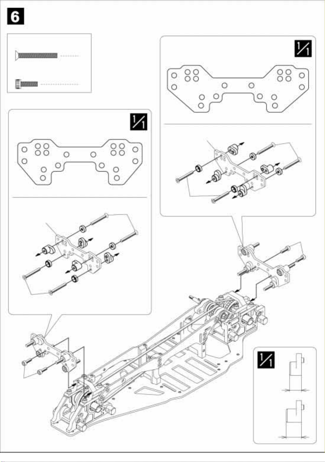
実物大で書いてあります。
Shown actual size.
絵を見て確認してください。
Check the diagram.
完全に締めてください。
Tighten screw securely.
SAFETY PRECAUTIONS
・First time builders should seek advice from experienced builders when assembling this.
・Please follow all safety precautions before operating this model.
・Be careful! Motor and speed control can get extremely after operating.
SV-34 5×10mmベアリング6個セット
5×10mm BEARING 6 pcs for SV-10
セッティングの章を参考にして下さ
い。
Refer to the setup recommendati-
ons.
オプションのベアリング(6個)を組
み込むことによって、余分ながたつ
きを抑えることができます。
Install optional ball bearings.
※製品改良のため、予告なく仕様を変更することがあります。
Spesifications are subject to change without notice.
説明書中の部品の価格は巻末の価格リストをご参照ください。
All prices of items in this manual are on back pages.