Steamist TSG-12 User manual
05/11 Pub. No. 200-G
- 1 -
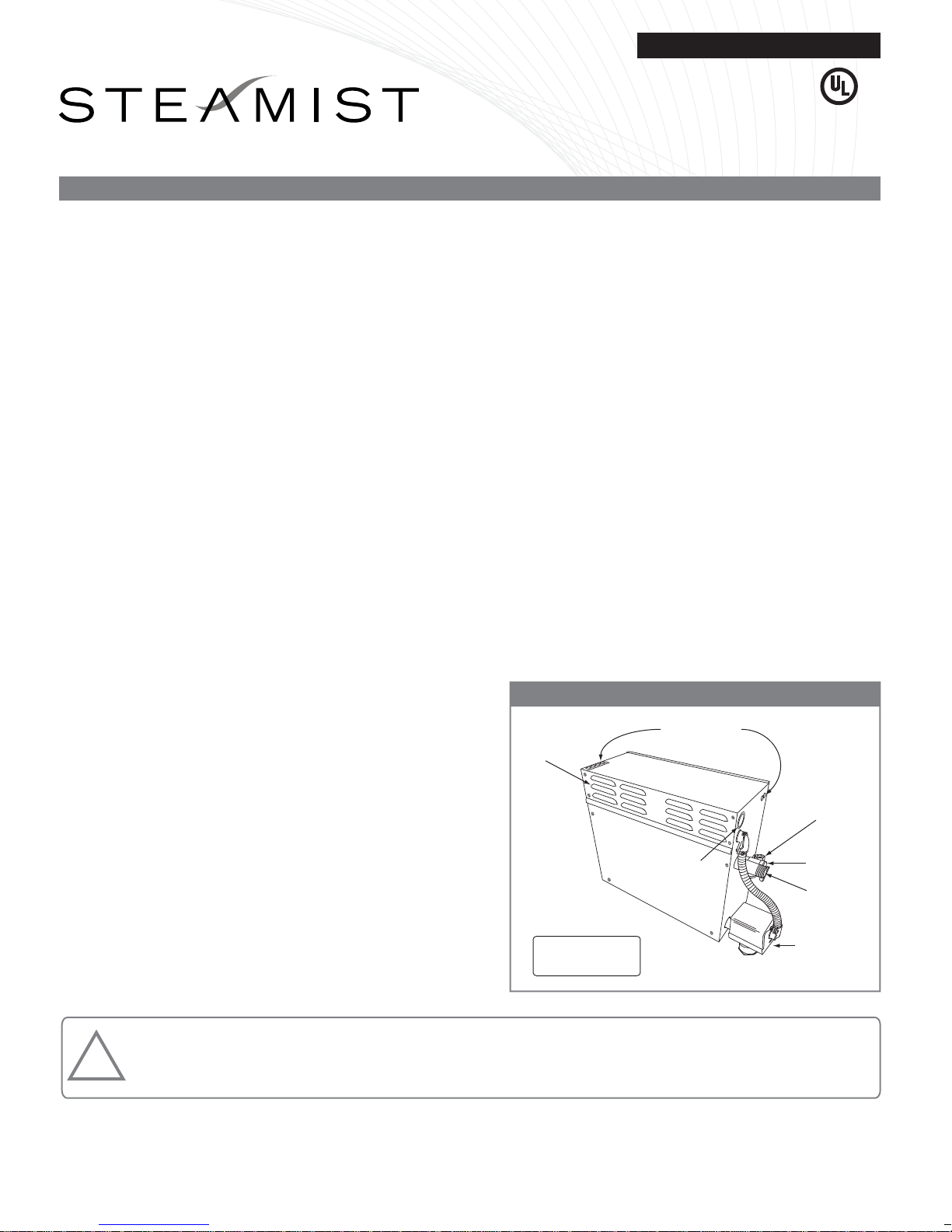
Optional Auto
Drain Installed
Model TSG-AD
Water Inlet
⅜" Compression
Fitting
¾" Safety
Relief Valve
¾" Steam
Outlet
Electrical
Panel Cover
Knockouts for
Electrical
Supply Line
Knockouts for
Control Cable
Install Upright
and Level
CUS
®
Model: TSG-12 & TSG-15
WARNING: Elderly persons, pregnant women, or those suffering from heart disease, high blood pressure, diabetes, or
who are otherwise not in good health, do not use this device unless directed to do so by a physician. Also, do not use
steambath while under the influence of alcohol. For additional Important Safety Information, please see a separate
instruction sheet Pub. No. 199.
!
IMPORTANT: The warranty of this product is voided if it is used in a commercial application or for anything other than a residential
steambath installation. All electrical connections must be performed by a licensed electrician in accordance with Local and National
Electric Codes. This product is not intended for use with Home Automation systems.
Electrical Installation Instructions
Steambath Generators
The Steamist “TSG” Generator operates with only “TSC” series
controls mounted inside and an optional TSX or TSR remote
control located outside the steamroom. It’s small enough in size
to be tucked away using very little space in a vanity, closet, or
basement, but large enough to provide steam for most residential
baths.
The Steamist “TSG” Steambath Generator comes factory
assembled, carefully wired and tested.
NOTE: A “TSC” series control is required to operate the "TSG"
generator.
1. Pre-Installation
a) Proper electrical supply (208 or 240 Volt): See rating
label on Steam Generator and Chart on page 4.
Determine proper size of wire, voltage, amperage, and
phase for the Steam Generator. 90°C copper wire is
required for generator connection.
b) In-line fuse/circuit breaker required: Fuse/circuit breaker
to be installed must be sized in accordance with chart
on back page. Do NOT install a GFI (Ground Fault
Interrupter) to this equipment (per article 210-8 in the
National Electric Code).
c) Route power supply cable to the location where the
Steam Generator will be installed (before walls are
closed).
2. Electrical Rough-in
a) Route appropriate power cable to the location the Steam
Generator will be installed. If receptacle is desired,
mount the box for the receptacle near the location of
the Steam Generator.
NOTE: The plug and receptacle require a rating of no
less than 250V and proper amperage. Refer to chart on
page 4 for amperage rating.
After the walls are complete, the Steam Generator and
Control can be wired.
3. Steam Generator Electrical Installation
WARNING: All power to the Steam Generator must be
turned off.
a) Remove the four screws holding the electrical access
cover and remove cover.
b) Locate the supply line knockout. Mount proper strain
relief into knockout hole.
c) Strip back power cable’s outer insulation jacket
eight inches and insert into Steam Generator.
Strip back insulation ½" from the three (3)
incoming wires (two power and one ground).
d) Insert ground wire into grounding lug located
on the right side of the electrical compartment
and secure.
CAUTION: Be sure the ground wire does not
come in contact with a live electrical part.
e) Locate the terminal/fuse block in the upper portion
of the electrical compartment. Insert power wires
into the power lugs on the front of the terminal/fuse
block and secure.
4. Optional Auto Drain Valve Connection
a) Open knockout for Auto Drain Valve conduit
connection.
b) Route flexible conduit from valve to knockout and
secure.
c) Connect two wires from valve to the auto drain
connection J8 on the printed circuit board (see
Figure 2).
Figure 1 - Steam Generator
®
05/11 Pub. No. 200-G
- 2 -
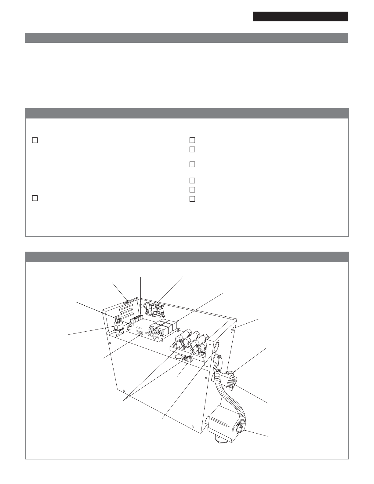
Optional Auto Drain
shown installed
Power Supply
Modular Jacks
Knockouts for
Control Cables
PC Board
Knockouts for
Control Cables
Knockouts for
electrical
supply line
208/240 Volt
incoming power
connections
Ground
Optional Auto
Drain Connection
Water Inlet
⅜" Compression
Fitting
¾" Steam
Outlet
Safety
Relief
Valve
Water
Level
Probe
DIP Switches
for Ganging
Generators
Electrical Installation Instructions
Figure 2 - Internal Electrical Connections
The Steam Generator is installed in an upright position.
The proper sized 90°C copper wire and circuit breaker
have been used.
The circuit breaker is NOT a GFI (Ground Fault
Interrupter) type.
The Steam Generator is properly grounded.
The circuit breaker or disconnect switch is on.
Water supply is open to the Steam Generator.
Checklist
Before starting, insure that the conditions of the following checklist have been met:
The proper size Steam Generator has been selected by
using the sizing page in the “Full Line Brochure,” “Pricing
Guide,” or “The Generator Sizing Guide” in the Residen-
tial Systems/Steambath Product Information section of
the Steamist website - www.steamist.com.
CAUTION: An improperly sized Steam Generator will
NOT produce the amount of steam necessary to reach
selected temperature.
The proper voltage Steam Generator has been selected
(i.e., 208V or 240V). A 208V Generator operating on
240V will damage the heating element, and a 240V
Generator operating on 208V will result in a 25%
loss of power.
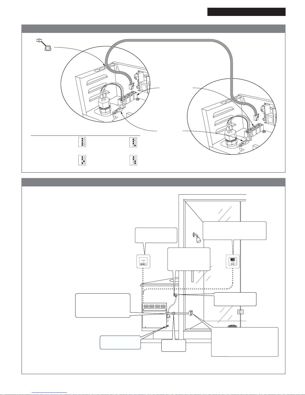
5. Ganging Mulltiple Steam Generators
IMPORTANT: When ganging 2 to 4 steam generators
together an additional 3199 steam head and 5158 control
cable must be purchased for each additional generator.
a) Locate the Control Cable knockout at top of steam
generator. Mount proper strain relief into knockout hole.
b) Route 5158 control cable from any one of the 4 Modular
Jacks located on the circuit board to the steam genera-
tor to be ganged (see Figure 3).
c) Set DIP Switches on each additional Steam Generator's
main PCB as shown in the Gangable Generators chart
(see Figure 3).
Model: TSG-12 & TSG-15
05/11 Pub. No. 200-G
- 3 -
Steam Outlet Pipe - Use a minimum of a ¾"
Copper or Brass pipe.
CAUTION: Do NOT install a shutoff valve on the
steam outlet pipe. Do NOT create traps or valleys
in this line which would prevent the flow of steam.
The steam outlet pipe should be pitched toward
the Steam Generator (preferred), allowing conden-
sation to run back into the Steam Generator or
toward the steamhead. If the steam pipe exceeds
ten feet, use an appropriate pipe insulation rated
for a minimum of 212°F.
Slope ceiling 2" per foot
TSC Series Control
Control MUST be installed inside
the Steam room.
Steamhead Installation
Steamhead should be mounted 18"
above the finished floor or 6" above
the rim of the tub as far from the
bather as possible.
Safety Valve
Connect ¾" pipe to an
indirect waste or as required
by local codes.
Connect to Hot or Cold
water supply
Auto Drain Ready
½" Capped Line
The Plumbing Instructions must be given to the homeowner for future use.
⅜" Shutoff Valve
Keep in open position
during normal
operation.
STOP
2
12
1
TIME
TEMP
IM
STOP
TSX Auxilary Outside
Control
Union
Required
Generator 1:
All 4 Switches to the left
(Factory Default Setting)
1 2 3 4
1 2 3 4
1 2 3 4
1 2 3 4
Generator 2:
Set Switch 1
to the right
Generator 3:
Set Switch 2
to the right
Generator 4:
Set switches 1 & 2
to the right
SW1 DIP Switch Settings for Multiple
Steam Generators on Processor Board:
Modular Jacks:
All four modular jacks are
identical and work in
any combination.
Connect to any jack.
Generator 1
Generator 2
25' Control Cable Part# 5158
Insert strain
relief clamp
into knockout
DIP Switches
Electrical Installation Instructions
Figure 3 - Ganging Steam Generators (when applicable)
Figure 4 - Typical Installation
Model: TSG-12 & TSG-15
- 4 -
05/11 Pub. No. 200-G
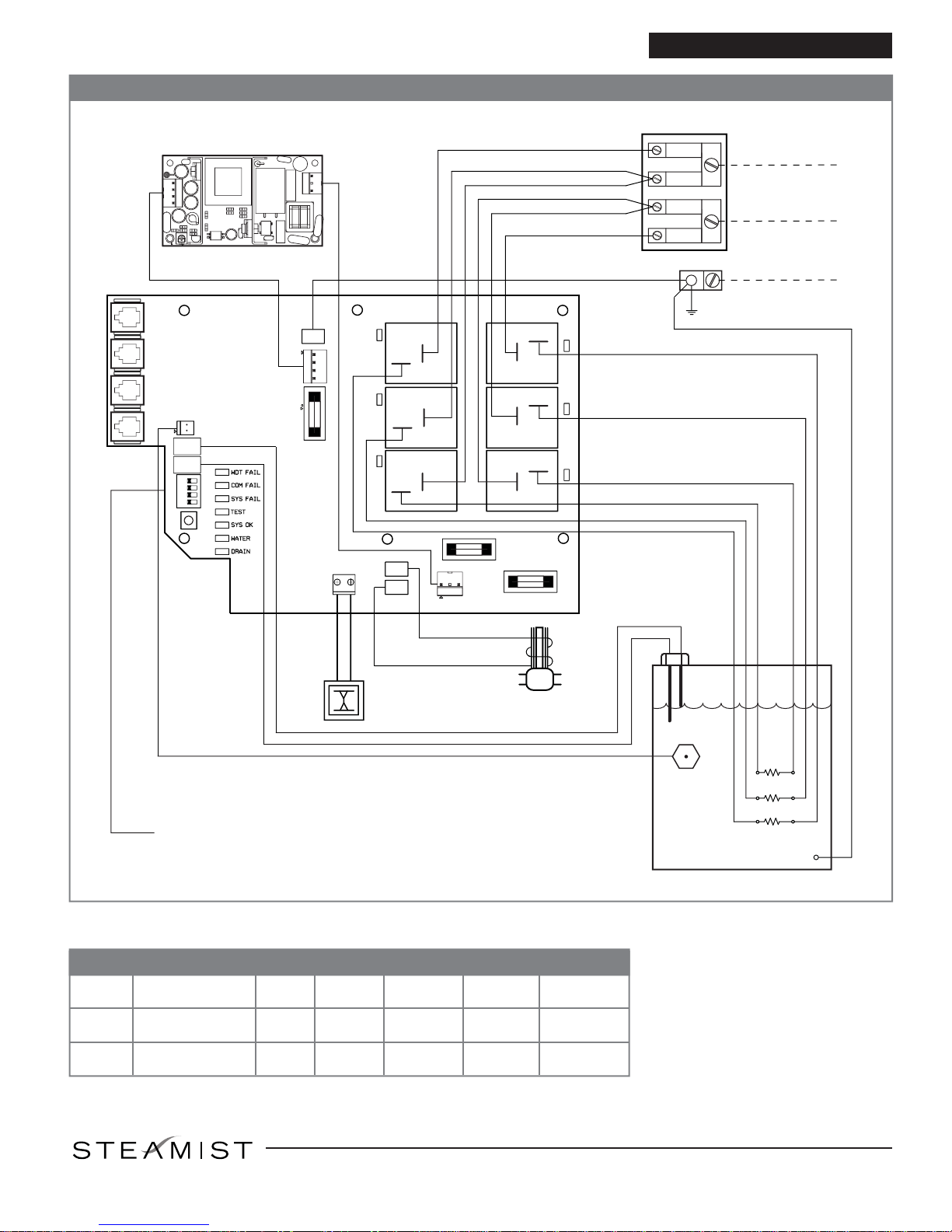
Water
Level
Probe
GN
Heating
Elements
Temperature
Sensor
TANK
AUTODRAIN
DS2
DS1
DS3
DS4
DS5
DS6
DS7
XL
H
Water
Solenoid
Valve
Optional
Auto Drain
Valve
STEAMIST, INC.
ASSEMBLY NO. 007-3420
0.5A 208/240VAC
0.5A 208/240VAC
P6
P7
W.S.
J8
GND
J2
F1
J4
J5
J6
J7
SW2
J1
F2
F3
DS9
RH1_L2
RH2_L2
RH3_L2
RH1_L1
RH2_L1
RH3_L1
DS11
DS13
DS8DS10
DS12
SW1
1 2 3 4
TEST
P1
P2
P3
POWER SUPPLY
J3
FUSE BLOCK
Ground Lug
208-240VAC
Supply Connection
35A
35A L1
60A
60A
L2
GND
0.8A 208/240VAC
208-240VAC
15VDC
Model: TSG-12 & TSG-15
Figure 5- Wiring Diagram
Electrical Installation Instructions
90°C copper wire is required for
generator connection. Installation
shall be in accordance with NEC and
local electrical codes.
Specication Chart
Model
No. Max. Cu. Ft.
For Area Up To KW Volt Phase Amps Breaker
Size
TSG-12
TSG-15
550
675
12
15
240
208
240
208
1
1
1
1
50
58
63
72
60
70
80
90
25 E. Union Ave., East Rutherford, NJ 07073 • Tel: 800-577-6478 • Fax: 201-933-0746
West Coast Office: Tel: 800-355-6478 • Fax: 661-940-1617
®
See Figure 3 for SW1 DIP Switch settings
This manual suits for next models
1
Other Steamist Inverter manuals


Popular Inverter manuals by other brands

IO-Power Technology
IO-Power Technology IOP-USSS-12V3556-OA Series user manual

SOLINTEG
SOLINTEG INTEG M MHS Series Quick installation guide

Xantrex
Xantrex Freedom SW 2000 installation guide

Mission Critical
Mission Critical xantrex XPower 3000 owner's guide

Kimo
Kimo FrigoPack EC FU+/12 quick start guide

Omron
Omron 3G3MX2-AB001-E instruction manual


