Steamist HC-9 User manual
HEAVY COMMERCIAL
STEAMBATH GENERATOR
OWNERS MANUAL
Models HC-9 Thru HC-18
3/98 Pub. No. 400- G

TABLE OF CONTENTS
I. Plumbing Installation...............................................................................................................1
A. Plumbing Pre-Installation ..................................................................................................1
B. Plumbing Rough-In .............................................................................................................1
C. Steam Generator Plumbing Installation............................................................................2
Title Page
11. Electrical Installation ...............................................................................................................2
A. Electrical Pre-Installation ...................................................................................................2
B. Electrical Rough-In .............................................................................................................2
C. Steam Generator Electrical Installation............................................................................2
III. CP-1 Control Package Installation and Operation ................................................................4
A. Pre-Construction Considerations .......................................................................................4
B. CP-1 Control Package Rough-In ........................................................................................5
C. CP-1 Control Package Installation .....................................................................................5
D. Steam Solenoid Valve ...........................................................................................................6
E. Operation ..............................................................................................................................6
IV. Auto Blowdown and Automatic ON/OFF Time Clock............................................................8
V.Steam Generator Operation......................................................................................................8
VI. Steam Generator Maintenance..................................................................................................8
A. Manual Blowdown ................................................................................................................8
B. Periodic Inspection ...............................................................................................................8
LIST OF ILLUSTRATIONS
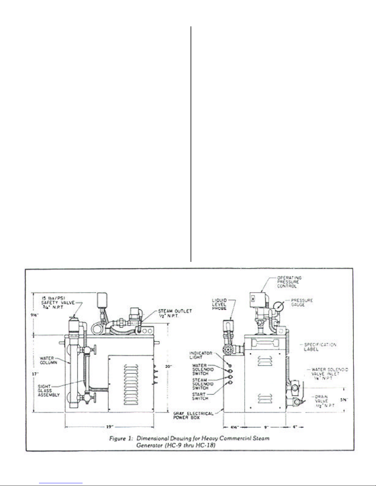
1. Dimensional Drawing for Heavy Commercial
Steam generator (HC-9 thru HC-18) ....................................................................................1
2. Typical Steam generator Installation ........................................................................................3
3. ST-200C Temperature Sensor Installation ...............................................................................4
4. ST-200C Temperature Control Installation .............................................................................5
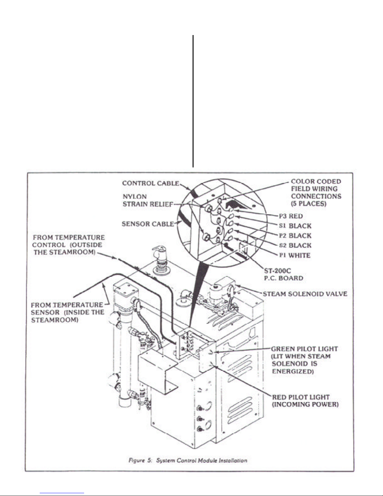
5. System Control Module Installation .........................................................................................6
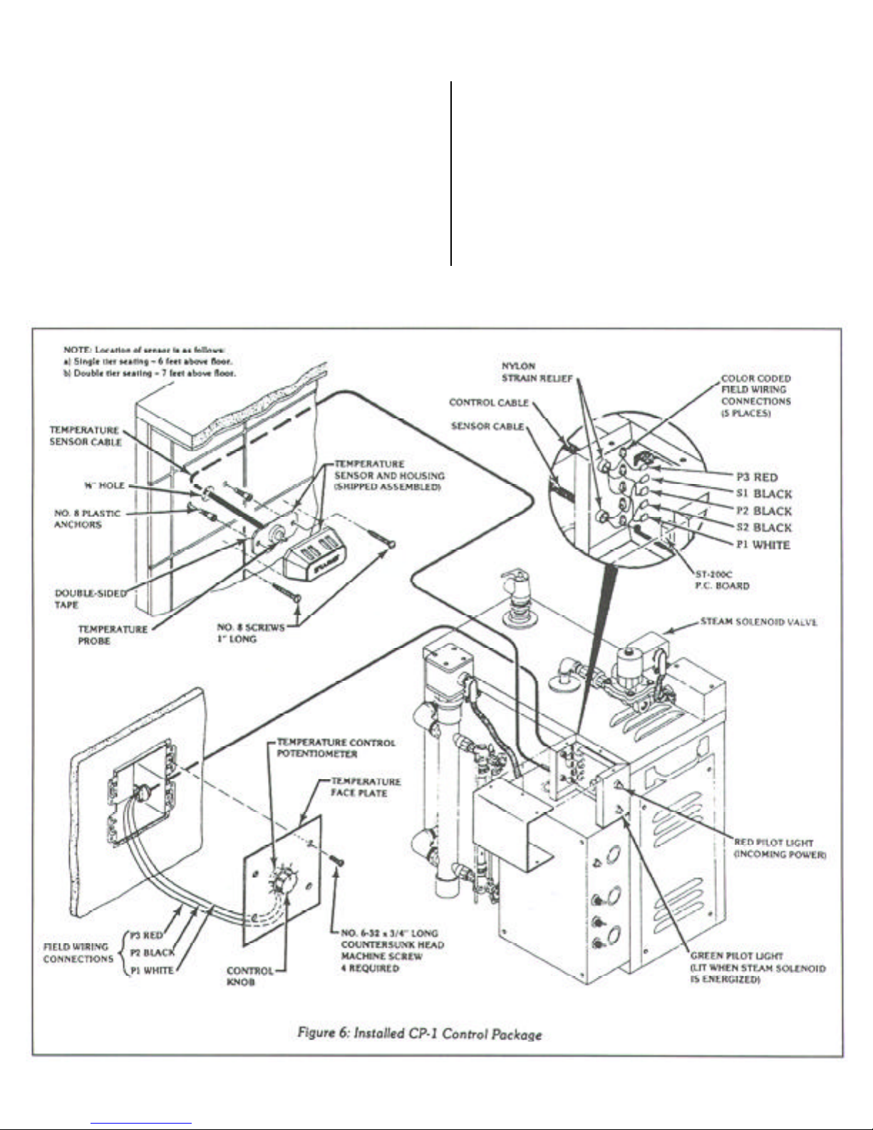
6. Installed CP-1 Control Package...............................................................................................7
7. Automatic Blowdown and Automatic ON/OFF Time Clocks...... ............................................9
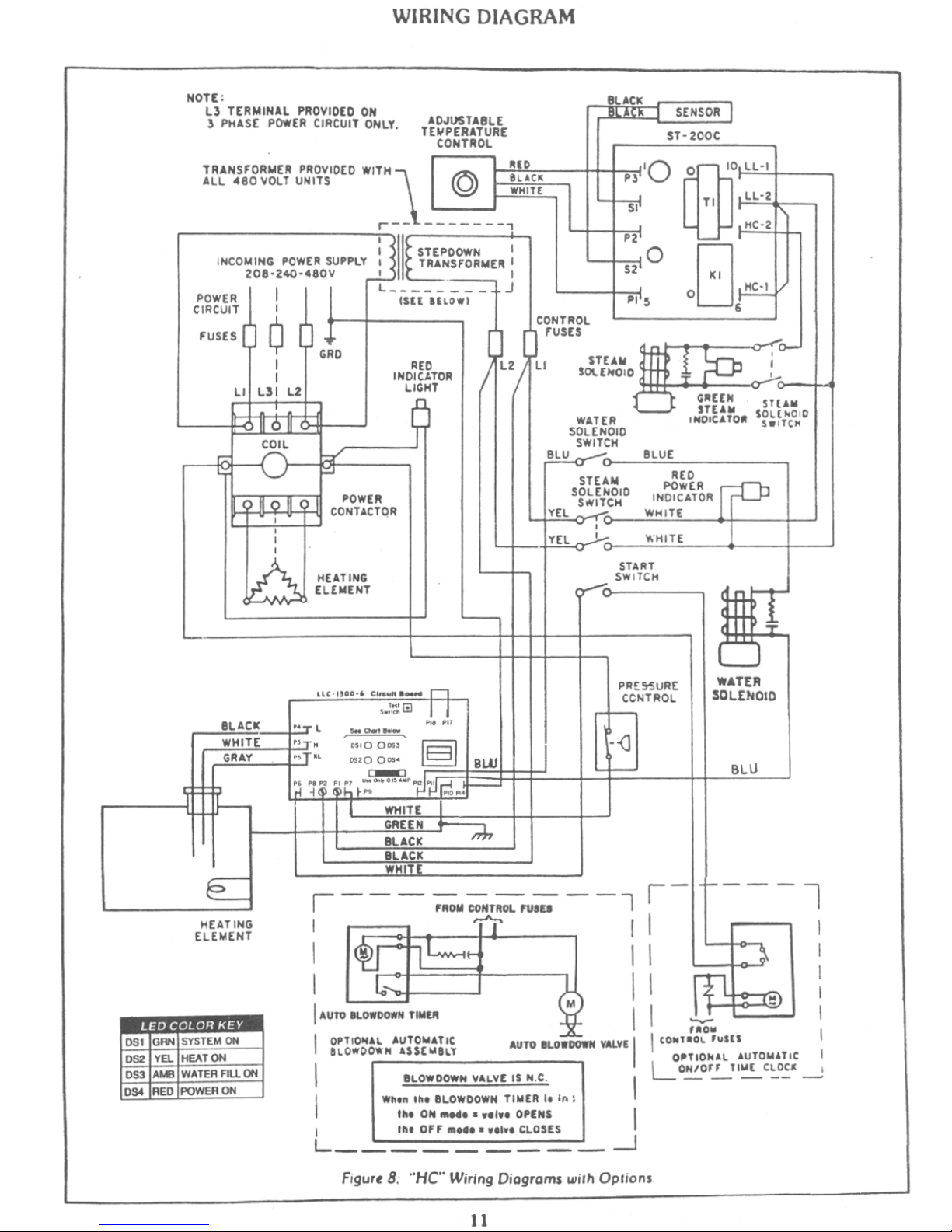
8. “HC” Wiring Diagram with Option..........................................................................................11
IMPORTANT: Read all instructions before installing equipment
Steamaster Company Inc., 1998
Figure Page
System Control Module Installation
PLUMBING INSTALLATION
The Heavy Commercial Steam Generator (HC-9 thru
HC-18) comes factory assemblect, carefully wired, and
tested.Allworkmustconformtolocalandnationalcodes.
All power must be OFF to the steam generator when
Installing or servicing the unit.
WARNING - Elderly persons, pregnant women, or those
suffering from heart disease, high blood pressure,
diabetes, or not in good health must not use this device
unlessdirectedbyaphysician. Also. steambathing should
be avoided while intoxicated.
I. PLUMBING INSTALLATION
A. Plumbing Pre- Installation
Allow sufficient room (30" minimum) for
access to the unit in the event service is
required. Do not keep flammable materi-
als such as gasoline, thinners, paints, etc.
In the same area as the steam generator.
The steam generator must be located as
close as possible to the steamroom. If the
steam generator is more than ten feet from
Insure that the model steam generator
unit you have purchased is sized ad-
equately for your steamroom.
1)
2)
3)
the steamhead, Insulate the steam pipe.
The serial number plate should be vis-
ible. Refer to Figure 2 for Installation
drawing. Do not Install outdoors or an
area where parts may freeze or corode.
Also, do not install near combustible
materials, i.e., paints, thinners, chlorine,
etc.
The steamroom must be completely sealed
on all sides. top, and bottom. Floor. walls,
and ceiling should be completely covered
with waterproof material. In the event that
the walls or ceiling are exposed plaster.
sheetrock, or plaster board, a waterproof
paint must be applied to seal the surfaces.
4)
B. Plumbing Rough-in
The Heavy Commercial “HC” Steam Generator
req,tires the following connec. tions: 1/2" NPT
piping for water inlet. 3/4" NPT brass or 3/4"
(I.D.)copper tubing for steamoutlet. and 3/4" NPT
safety valve should be piped to an indirect waste
line. A 3/4" minimum indirect waste line must be
installed for the drain. This should be completed
before wa!ls are installed.
Before connecting the water line it is important to
make sure the line is thoroughly clean and free of
foreign matter.
Rough-in a water line from hot (prefer-
ably) or cold water pipe; brass pipe or
1)
1

ELECTRICAL INSTALLATION
copper tubing is recommended. A shut-
off valve should be convenicnitly placed
in the water feed line.
Rough- in the steam line using 1/2" NPT
brass pipe or 3/4 " I. D. copper tubing. Do
not use iron pipe. it will rust and discolor
wall of steamroom. For a steam line that
is longer than 10 feet, insulation must be
used. The stearnhead location should be
approximately 12” to 18" above the
steamroom floor.
CAUTION: NO shut-off valve should be
installed on the steam line. Do not create
trapsor valleys in thisline which would trap
condensation and block the flow of steam.
Thesteampipeshouldbepitchedawayfrom
thestearnhead allowingcondensation to run
back into steam generator (Preferably) Or
pitched toward the steamhead.
Rough- in a 3/4" indirect waste line to be
used for the safety valve and drain. The in-
direct drain must be in accordance with lo-
cal plumbing codes.
2)
3)
C. Steam Generator Plumbing Installation
Care must be taken when installing the steam
generator. Leave proper access for servicing
(30'’ minimum each side). (Refer to Figure 2
for typical steam generator installation.)
CAUTION: The steam generator is designed
to be used ONLY in an upright and level posi-
tion ; to do otherwise would damage the unit
and void the warranty.
If needed mount the steam generator on a
platform to allow draining into a basin or
into previously installed indirect waste line.
NOTE: Optional automatic blowdown must
be piped into the 3/4" indirect waste line.
Connect the 3/4" NPT safety valve into ihe
previously installed indirect waste line.
In areas where high water pressure may be
a problem a water hammer arrestor should
be installed. Connect the water supply to
the steam generator connection marked
“water inlet”. (See Figure 1.)
Connect the steam line from the preViously
roughed-in location to the steam solenoid
valve on the generator marked .. steam out-
let”. (See Figure 1.)
1)
2)
3)
4)
In the steamroom. place the center of the
escutcheon onto the steam pipe and Screw
the stearnhead into place. Care must be
taken not to Scratch the stearnhead or es-
cutcheon with a wrench. Be Sure the steam
slot in the stearnhead is facing down.
After the plumbing connections are complete
the electrician may finish the wiring and test
the unit.
II. ELECTRICAL INSTALLATION
Electrical Pre- Installation
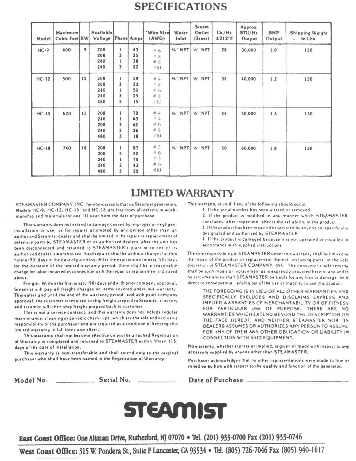
Proper electrical supply: see specification
label located above the drain valve (see Fig-
ure 1)Determine proper size of wire,voltage,
amperage. and phase for the steam genera-
tor.
Inline fuse/circuit breaker required: fu or
circuit breaker sized in accordance with
specification label. Do not install a (GFI)
Ground Fault interrupter to this equip-
ment.
B. Electrical Rough-In
Route power supply cable to the location the
steamgenerator will beinstalled before walls
are closed.
C. Steam Generator Electrical Installation
WARNING ALL POWER TO THE STEAM
GENERATOR MUST BE TURNED OFF.
Locate appropriate knockout found on top
of the steam generator. Mount proper stain
relief into knockout hole.
Strip back the power cable’ s outer insulat-
ingjacket twelve inchesand insert intosteam
generator. Strip back insulation 1/2" from
the incoming wires; single phase (two power
and one ground). 3 phase (three power and
one ground).
Insertgroundwireintogroundingluglocated
on the lower left side wall of the gray elec-
trical power box.
CAUTION: Insure ground wire does not
come in contact with live electrical connec-
tions.
Locate the fuse block. found in the upper
part of the gray power box. Insert power
wires into the proper power lug terminals
on top of the fuse block and secure.
5)
A.1)
2)
1)
2)
3)
4)
5 )
2
Locate and remove six (6) screws securing
the access cover to the gray electrical power
box. (See Figure 1.)
1)

ELECTRICAL INSTALLATION
Replacecoverandsecure screws removed
in step 1
6)
NOTE: Steam Generator will not operate
without water.
3
If connections are made properly the indi-
cator lamp will illuminate when the
7)
generator is heating.

CP-1 CONTROL PACKAGE
CP-1 CONTROL PACKAGE INSTALLATION
AND OPERATION
The CP-I Control Package is completely automatic in
operation... room temperature is thermostatically con-
trolled by the Steamist ST-200C Solid State Temperature
Control System in conjunction with the generator’s steam
solenoid valve. No attendant required... set it, forget it.
The “rapid response” ST-200CTemperature Control Sys-
tem is made up of three components: Temperature Sensor
Probe (Figure 3), Temperature Control Panel (Figure 4),
and System Control Module (Figure 5). After installation
of the ST200C is complete the steamroorn temperature
will automatically be maintained within 1-1/2 F of the
desired setting.
NOTE: This control is not an ON/OFF switch, it is used
in conjunction with the Steam Solenoid Valve. The steam
generator cannot be turned OFF with this device.
A. Pre - Construction Considerations
Choose a location to mount the Temperature Con-
trol Panel. If only a manager or limited group will
be in charge of controlling the steambath tempera-
ture, a utility area may be appropriate.
If steambathers will be permitted to adjust the tem-
perature, choose a convenient location outside the
steamroom door.
Mount the Temperature Control Panel OUTSIDE
the steamroom. Mount the Temperature Sensor
Probe INSIDE the steamroom.
WARNING: Allelectrical powerto the steam gen-
erator MUST be turned OFF before proceeding
with installation.
B. CP-1 Control Package Rough-in
The 3 wire cable for Temperature Control Panel to
be used during installation of the ST200C Solid
State Temperature Control System is low voltage;
18 or 22 AWG wire recommended. Every attempt
should be made to match the color wire of the Tem-
perature Control Potentiometer lead wires (P1
white, P2 black, and P3 red) to the 3 wire cable.
Install a metal two-gang switch box rotated 90
(refer to Figure 4). Install an inverted strain re-
lief clamp and feed the 3 wire cable into the
two -gang box. Run the 3 wire came from the
switch box to the steam generator’s location.
1)
STEPS TO INSTALL SENSOR
SEPARATE TWO WIRES OF CABLE (COMING THRU
WALL FROM GENERATORS ST 200C CIRCUIT
BOARD, TERMINAL #2 AND #4) APPROX. 2", STRIP
AND TWIST APPROX. 1/2" OF BARE WIRE.
TAKE NEW SENSOR ASSEMBLY AND TWIST WIRES
TO WALL CABLE AND SECURE WITH WIRE NUTS.
PEEL OFF ADHESIVE BACKING FROM SENSOR.
CAREFULLYAPPLYSILICONESEALANTAROUND
REAR EDGE.
FEED WIRES BACK INTO WALL AND PRESS SENSOR
FIRMLY TO WALL (BE CAREFUL TO ALIGN PLATE
HOLES WITH ANCHOR HOLES).
INSTALLSCREWS,AND SNAPCHROME COVERBACK
IN PLACE.
TEMPERATURE SENSOR ASSEMBLY MUST FORM A
100%WATER TIGHT SEAL TO THE WALL USING SILI-
CONE SUPPLIED.
1)
2)
3)
4)
5)
6)
7)
Note: Location of sensor is as follows:
a) Single tier seating - 6 feet above floor.
b) Double tier seating - 7 feet above floor.
III
4

CP-1 CONTROL PACKAGE
Install the cable from the area of the Tem-
perature Sensor (Probe) to the steam
generator’s location. The Temperature Sen-
sor (Probe) MUST be located inside the
steamroom. In steamrooms with singletier
seating the Sensor should be located 6 feet
abovethe floor, withtwo tier seating it should
be 7 feet above the floor and in either case
away from the steamhead and steamroom
door. The connector end of the wire must be
installed inside the steamroom. NOTE: A
5/8 inch hole should be provided so that the
connector can be passed through the wall for
installation found later in these instructions.
2)
CP-1 System Control Package Installation
Temperature Sensor (Probe ) (for installation
inside the steamroom)
C. 1)
Locate the 2 wire cable described in the
Rough-in section.
a.
Keeping the 5/8 inch hole centered, drill two
1/4 inch holes 2 inches apart. Insert 2-No. 8
plastic anchors into drilled holes.
b.
c. Follow Figure 3.
Temperature Control Panel (for installation out-
side the steamroom )
2)
Attach the 3 wires (P1, P2, and P3) from the
Temperature Control Potentiometer to the 3
wire cable in the two-gang box. Note the
colors of wire P1, P2, and P3 are attached to
match the colors of the 3 wire cable to the
potentiometer wire colors.
a.
Secure Temperature Face Plate to the two-
gangbox usingfour (4) machine screws. (See
Figure 4.) Important: Care must be taken
to mount Temperature Face Plate properly.
b.
5
CP-1 CONTROL PACKAGE
3) System Control Module
Remove screws securing cover to Sys-
tem Control Module and remove cover
(Figure 5).
a.
Feed the 3 wire cable through the top
strain relief. three inches into the control
module. Attach wires as shown in the
blowup (Figure 5).
Feed the 2 wire cable through the lower
strain relief, three Inches into the control
module. Attach wires as shown in the
blowup (Figure 5).
Check that all connections are made
b.
c.
d.
in accordance with Wiring Diagram
(See Figure 7.)
e. Replace control module cover.
D. Steam Solenoid Valve
There is no installation required for the steam
solenoid valve. it is factory installed and
wired.
E. Operation
The temperature of the steambath is regu-
latedautomatically by the ST-200CTempera-
tureControl System whichturns “On orOff”,
the Steam Solenoid Valve located on the
steam generator allowing steam to enter the
room.
6
CP-1 CONTROL PACKAGE
To INCREASE the temperature, turn the knob on
the Temperature Control Panel clockwise; the
HIGHER THE NUMBER, THE HIGHER THE
SETTING (numbered 1 to 10).
To DECREASE the temperature, turn the knob
counterclockwise.
Once a desired temperature setting has been estab-
lished there should be no further need for additional
adjustments.
IMPORTANT.
To check the function, two lights are provided on
the exterior of the System Control Module located
on the steambath generator. The “Red Light” indi-
cates there is electrical power to the Temperature
Control Module. The “Green Light” indicates the
Steam Solenoid Valve is energized.
If a malfunction should occur in either the incom-
ing electrical power supply “Red Light” or the
Steam Solenoid Valve “Green Light” then the ap-
propriate light will not be lit. However, the “Green
Light” will cycle “ON and OFF” to indicate mode
of the Steam Solenoid Valve.
7

AUTOBLOWDOWNANDAUTOON/OFFTIMECLOCKS
The “HC” steam generator, with an optional auto blowdown sys-
tem, will automatically purge the steam boiler. Working in con-
junction, the Time Clock and electrically motorized valve, which
allows blowdown on boilers, prevents excessive mineral and scale
build-up.
IV.
A. Installation
1. Auto Blowdown Drain Valve (plumbing)
Attach the main blowdown drain valve to 3/4" indirect drain
(most local codes require a blowdown tank). A strainer must
not be used with the valve. Note: the drain line must be angled
downward, allowing gravity to properly drain the machine.
2. Auto Blowdown (electrical)
All wiring is done at the factory so that no special electrical
wiring is necessary.
B. Operation
First decide the TIME OF DAY you require the boiler to
blowdown. It is recommended to select a time while the boiler
is in use, but under low demand. For best results program the
Timer to blowdown every day of use for a period of 5 minutes.
The blowdown will begin with the Timer “ON” command and
end with the Timer “OFF” command. See Page 9 and 10.
C. SETTING AUTOMATIC ON/OFF TIME CLOCK
The Steam Generator will turn ON with the Timer “ON” com-
mand and OFF with the timer “OFF” command. See Page 9
and 10.
IMPORTANT. The Auto Blowdown Timer and Auto On/Off
Timer are two separate timers. If your steam generator only
has one timer, then only one of these two options can be pro-
grammed. Check with the installer to see which option has
been purchased.
V. STEAM GENERATOR OPERATION
A. Place START, WATER SOLENOID, and STEAM SOLE-
NOID switches in the ON position. The Water Solenoid Valve
will open and the boiler will fill to its proper level (one-half to
two-thirds of the sight glass full) and automatically shut-off.
B. When there is adequate water in the boiler the power contactor
will energize and the red power light will illuminate indicating
that the boiler is heating up.
NOTE: This boiler is equipped with a Solid State Liquid Level
Control System. Water level is maintained in the boiler, by a
ground potential signal between each stainless steel water level
probe and the boiler, and operates by sensing the electrical resis-
tance of water.
Both the water feed and low water cut-off functions are regulated
bya low voltage electrical signal that activates the control relay(s),
depending on the water level within the boiler which, in turn,
energizes the water solenoid valve and/or power contractor.
C. When adequate steam has been generated from the boiler
and the desired temperature reached in the steamroom the
steam solenoid valve will close: when controlled by the ST-
200C. The steamroom is now ready for use. Note: When the
steam solenoid valve closes the red pilot light above the toggle
switches will go out only after steam pressure builds to ap-
proximately 8 to 10 PSI within the boiler.
The boiler will maintain an 8 to 10 PSI steam pressure by use
of a pressure control which is supplied as standard equipment.
The pressure control will cycle the unit ON and OFF auto-
matically when the steam solenoid valve is OFF and the room
temperaturecontrol is satisfied.If the solenoidvalve is OPEN,
the pressure in the boiler will drop and the red light will stay
ON.
D. If a ST-200C Temperature Control System (Thermostat) is
provided, set the dial to the desired TEMPERATURE (Dial
Calibration: 1 to 10 setting for comfort level). (Refer to Sec-
tion III for Operating Instructions.)
E. If an Automatic ON/OFF Time Clock is provided, set “the
timer cycle” in order to operate the steambath generator.
VI. STEAM GENERATOR MAINTENANCE
A. MANUAL BLOWDOWN (Only if not equipped with
Automatic Blowdown)
The boiler should be blown down on a daily basis to purge the
vessel of mineral deposits and possible scaling. For effective
blowdown, the STEAM, WATER, and START switches must
be placed in the OFF position. The drain valve should be
opened completely, allowing the boiler water to exit through
your drainage piping into an indirect drain. Now, place the
water solenoid switch in the ON position allowing the system
to flush through for approximately 5 minutes. Close the drain
valve and allow the boiler to fill with water until the proper
level has been reached. The generator is again ready for use,
place the START and STEAM switches in the ON position.
B. PERIODIC INSPECTION
CAUTION: Disconnect all power to boiler before servicing.
Service should be performed by a qualified person.
Check electrical connections periodically, to ensure that
they are tight.
Remove flange-type element to clean any scale that might
have built up on sheath of heating element(s). Be careful
when cleaning heating element, not to deform the rods.
1.
2.
3.
8
Remove Liquid Level Probe periodically to check for
deposits.Check that thebottom union,which attaches
the water level probe assembly is clean of deposits. If
necessary, clean stainless steel probes and teflon insu-
lated tubing by removing all foreign matter. Extreme
care should be exercised so that porcelain insulators
are not damaged during the removal of Liquid Level
Probe. This will ensure proper conductivity and op-
eration of boiler.

Digi 20 Series
One Circuit Electronic
24 Hour or 7 Day Time Switches
FIGURE 7. Auto Blowdown and Auto ON/OFF Timeclock
Digi 20A
(surface mounting)
Operating Instructions
APPLICATION
Time based control of lighting, ventilating, heating, cooling or other electrical loads in commercial and industrial applications. The Digi 20 time
switches are programmable for 24-hour or 7-day schedules.
The Digi 20A is intended for either surface or rail mounting. The control is completely enclosed in a plastic housing and includes a terminal
cover and sub-base for installation and hard wiring.
The Digi 20E is intended for flush (panel) mounting.
All units are supplied with a clear plastic dust cover.
TECHNICAL DATA
Output-1 SPDT relay with dry contacts
Switch Rating: 16A/277VAC resistive
1 OOOW tungsten @ 240VAC; 50OW @ 120VAC
1/2 hp @ 120VAC; 1 hp @ 240VAC
100 hour capacitor back-up of memory and display
Supply voltages: Separate Models - 24VAC/DC, 120VAC,
208/240VAC, all 50/6OHz (refer to product label)
Shortest switch time-1 minute
Ambient Temperature Range -20 F to 140 F ( 28 C to 60 C)
VA required: 120V & 240V models: 4VA
24V model: 2VA @ 24VAC, 1VA @ 24VDC
Screw terminal connections (Digi 20A)
1/4" quick connects (Digi 20E)
Accuracy ± 4 minutes per year
WIRING
1. Disconnect the power.
2. Wire input to timer M to the proper
voltage marked on the unit. Wiring to
incorrect voltage will avoid the warranty.
3. Connect wiring according to the wiring
diagram. The terminals on the Digi 20A
sub base will accommodate 10 to 24 AWG
wire.
Mechanical Timer Shown
9

Other manuals for HC-9
2
This manual suits for next models
9
Table of contents
Other Steamist Inverter manuals


Popular Inverter manuals by other brands

Parkside
Parkside PSE 2800 A1 Operation and safety notes

Mitsubishi Electric
Mitsubishi Electric FR-A700 Series Technical manual

CONPO
CONPO SDC-20A instruction manual

WindTronics
WindTronics AURORA PVI-3.0-OUTD-W quick start guide

UnitedPower
UnitedPower IG3600S instruction manual

Growatt
Growatt SPF3000 Installation and operation manual

SMA
SMA SUNNY ISLAND 4.4M Quick reference guide

Endress
Endress ESE 30YW/RS Original operating manual

Mitsubishi Electric
Mitsubishi Electric FR-A8AP instruction manual

Growatt
Growatt SPH TL BL-UP Series installation manual

aptos
aptos MAC 800 Quick installation guide

Trotec
Trotec AIROZON 10000 Original instructions


