Steamist SM-15 User manual

05/11 Pub. No. 323-M
- 1 -
Optional Auto
Drain Installed
Model SM-900
Water Inlet
⅜" Compression
Fitting
¾" Safety
Relief Valve
¾" Steam
Outlet
Electrical
Panel Cover
Knockouts for
Electrical
Supply Line
Knockouts for
Control Cable
Install Upright
and Level
®
®
®
CUS
®
Electrical Installation Instructions
Steambath Generators Models: SM-12 and SM-15
The Steamist “SM” Generator operates with one or two controls
appropriately located inside and/or outside the steamroom. It’s
small enough in size to be tucked away using very little space in
a vanity, closet, basement, or an insulated attic, but large enough
to provide steam for most residential baths.
The Steamist “SM” Steambath Generator comes factory
assembled, carefully wired and tested.
NOTE: The SMC-120, SMC-150, TC-125, TC-150, TC-110,
TC-135, DSC-425, and DSP Controls are designed to work with
all Steamist “SM” Generators.
1. Pre-Installation
a) Proper electrical supply (208 or 240 Volt): See rating label
on Steam Generator and Chart on back page. Determine
proper size of wire, voltage, amperage, and phase for the
Steam Generator. 90°C copper wire is required for
generator connection.
b) Dedicated overcurrent protection device, such as an
in-line fuse/circuit breaker required: Fuse/circuit breaker
to be installed must be sized in accordance with chart
on back page. Do NOT install a GFI (Ground Fault
Interrupter) to this equipment (per article 210-8 in the
National Electric Code).
c) Route power supply cable to the location where the
Steam Generator will be installed (before walls are
closed).
2. Electrical Rough-in
a) At this time read through the installation instructions for
the selected control(s).
b) Route appropriate power cable to the location the
Steam Generator will be installed. If receptacle is
desired, mount the box for the receptacle near the
location of the Steam Generator.
NOTE: The plug and receptacle require a rating of no
less than 250V and proper amperage. Refer to chart on
page 4 for amperage rating.
After the walls are complete, the Steam Generator and
Control can be wired.
3. Steam Generator Electrical Installation
WARNING: All power to the Steam Generator must be turned off.
a) Remove the four screws holding the electrical access
cover and remove cover.
b) Locate the supply line knockout. Mount proper
strain relief into knockout hole (see Figure 2:
Internal Electrical Connections).
c) Strip back power cable’s outer insulation jacket
eight inches and insert into Steam Generator.
Strip back insulation ½" from the three (3)
incoming wires (two power and one ground).
d) Connect incoming ground wire to floating green
pigtail labeled “GND.”
CAUTION: Be sure the ground wire does not
come in contact with a live electrical part.
e) Connect incoming power to floating black pigtail
leads labeled “L1” and “L2” (see Figure 2: Internal
Electrical Connections).
f) The Steam Generator is ready for operation once
the installation of the controls is completed (refer to
separate Installation and Operating Instructions).
4. Optional Auto Drain Valve Connection
a) Open knockout for Auto Drain Valve conduit
connection.
b) Route flexible conduit from valve to knockout
and secure.
c) Connect two wires from valve to the two place
terminal strip provided (see figure 2).
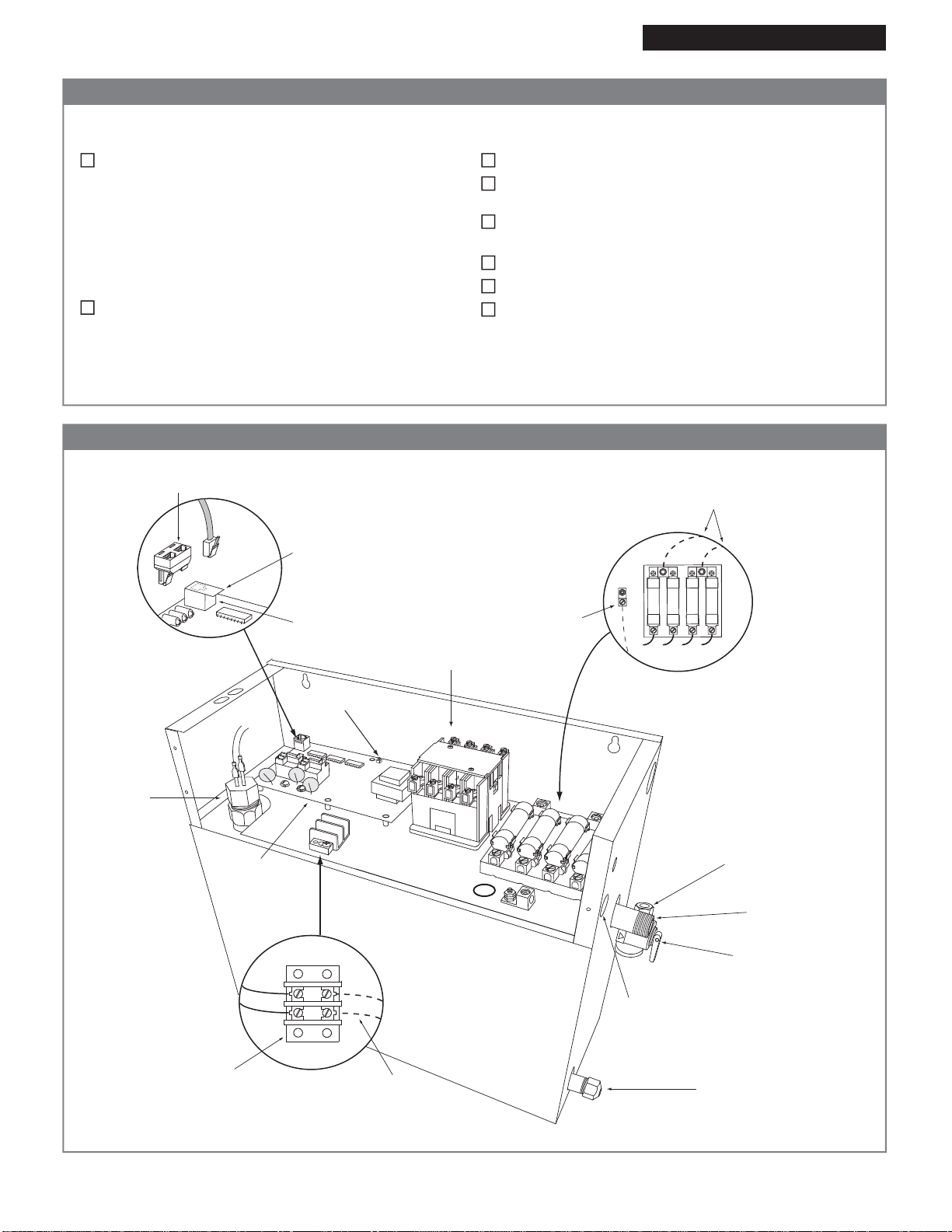
Figure 1 - Steam Generator
WARNING: Elderly persons, pregnant women, or those suffering from heart disease, high blood pressure, diabetes, or
who are otherwise not in good health, do not use this device unless directed to do so by a physician. Also, do not use
steambath while under the influence of alcohol. For additional Important Safety Information, please see a separate
instruction Pub. No. 199.
!
IMPORTANT: The warranty of this product is voided if it is used in a commercial application or for anything other than a residential
steambath installation. All electrical connections must be performed by a licensed electrician in accordance with Local and National
Electric Codes. This product is not intended for use with Home Automation systems.
®
05/11 Pub. No. 323-M
- 2 -
Single Phase
Connections Shown
Power Supply
L1 and L2
Ground
Optional Steamist Splitter
for Two Controls
Modular Jack
Protective Covering
“Remove Before
Installation”
Plug
Optional Auto
Drain Connection
Knockout
for Auto Drain
¾" Steam
Outlet
Safety
Relief
Valve
Water Inlet
⅜" Compression
Fitting
½" Outlet
When not equipped
with Auto Drain leave
drain line capped
and closed
Printed
Circuit
Board
Water
Level
Probe
Contactor/Relay
Terminal Strip
for Auto Drain
Connection
®
®
Test Switch
®
The Steam Generator is installed in an upright position.
The proper sized 90°C copper wire and circuit breaker
have been used.
The circuit breaker is NOT a GFI (Ground Fault
Interrupter) type.
The Steam Generator is properly grounded.
The circuit breaker or disconnect switch is on.
Water supply is open to the Steam Generator.
Electrical Installation Instructions
Checklist Models: SM-12 and SM-15
Figure 2 - Internal Electrical Connections
Before starting, insure that the conditions of the following checklist have been met:
The proper size Steam Generator has been selected by
using the sizing page in the “Full Line Brochure,” “Pricing
Guide,” or “The Generator Sizing Guide” in the Residen-
tial Systems/Steambath Product Information section of
the Steamist website - www.steamist.com.
CAUTION: An improperly sized Steam Generator will
NOT produce the amount of steam necessary to reach
selected temperature.
The proper voltage Steam Generator has been selected
(i.e., 208V or 240V). A 208V Generator operating on
240V will damage the heating element, and a 240V
Generator operating on 208V will result in a 25%
loss of power.

05/11 Pub. No. 323-M
- 3 -
START
STOP
®
TEMPERATURE
START
STOP
WARNING
HOLD THIS FITTING SECURELY WITH A PIPE
WRENCH WHILE MAKING A PLUMBING
CONNECTION TO THE WATER INLET IN ORDER
TOPREVENT INTERNAL DAMAGE TO THE WATER
SOLENOIDVALVE. 009-1054
CUS
®
LISTED995C
STEAMBATHGENERATOR
MODELNO.
SERIALNO. HEATERLOAD
VOLTS PH MAXAMPS kW
CONTROL CIRCUIT
VOLTS AMPS 50/60HZ
SERVICEBY AUTHORIZED PERSONNEL ONLY
APRODUCT OF STEAMIST CO., RUTHERFORD, NJ
IMPORTANT: Run the Control Cable through a ¾" conduit. Remove protective cap when making the
final connection to Control.
The Electrical Instructions must be given to the homeowner for future use.
SMC-150 or TC-150
Control MUST be
installed inside the
steam room.
NOTE: Unit must be wired with 90°C
copper wire in a suitable raceway, or, if
local codes allow, provide twist lock plug
on a 90°C copper wire cord from genera-
tor to a 250V 2-pole, 3-wire grounding
receptacle (amperage rating as required).
Control Cable
Route from
Control to Steam
Generator in a
¾" conduit.
Appropriately
fuse protected
208/240V field
wiring to Steam
Generator.
Inside Installation
Control should be mounted four
feet from the floor. Select a
location convenient to the
bather but not in a direct line of
Shower or Body Sprays and not
directly above the Steamhead.
SMC-120 or TC-125
Auxilary Outside
Control
®
®
Electrical Installation Instructions
Figure 3 - Typical Installation Models: SM-12 and SM-15

05/11 Pub. No. 323-M
- 4 -
LLC-1300-3 Circuit Board
P14
P12
P11
P16
P15
P10
P1
P2
P6
P8
P7
P9
P4
P3
P5
L
H
XL
P18 P17
DS1
DS2
DS3
DS4
See
Chart
Test
Switch
Fuse 0.15 AMP
P13
GND
COIL
Heating
Elements
TANK
WHT
GREY
BRN
RED
BLU
BLU
GRN
Water
Solenoid
Valve
Optional
Auto Drain
Valve
Auto Drain
Thermostat
Terminal
Block
Contactor/Relay
Fuse Block
YEL
YEL
RED
RED
ORG
BLK
BLK
Water
Level
Probe
GND
RED
Field
Connections**
ORG
L1
L2
L3
L4
T1
T2
T3
T4
GND
Noise
Filter
L1
L2
GRN
NOTES: *Supplied with Controller.
**Field Connections, use 90ºC copper wire
LLC-1300-3 Circuit Board
(Low Voltage)
Multi-Conductor
Cable*
Typical Steamist
Control
P14
P12
P11
P16
P15
P10
P1
P2
P6
P8
P7
P9
P4
P3
P5
L
H
XL
P18 P17
DS1
DS2
DS3
DS4
See
Chart
Test
Switch
BLU
WHT
GREY
Water
Solenoid
Valve
Terminal
Block
Optional
Auto Drain
Valve
GRN
Heating
Elements
Water
Level
Probe
Fuse 0.15 AMP
P13
GND
Auto Drain
Sensor
BLU
COIL
GND
BLK
BLK
BLK
YEL
BRN
ORG
ORG
BLK
BLK
RED
BLK
BLK
BLK
L1
L3
L2
T1
T3
T2
Noise
Filter
RED
RED
RED
Field
Connections**
YEL
TANK
GND
Contactor/Relay
L1
L3
L2
L3
L1
L2
GRN
NOTES: *Supplied with Controller.
**Field Connections, use 90ºC copper wire
®
TEMPERATURE
START
STOP
®
(Low Voltage)
Multi-Conductor
Cable*
Typical Steamist
Control
TEMPERATURE
START
STOP
®
Electrical Installation Instructions
SM-12/15 Single Phase Schematic Models: SM-12 and SM-15
SM-12/15 Three Phase Schematic
DS1
DS2
DS3
DS4
GRN
YEL
AMB
RED
TIMER ON
HEAT ON
WATER FILL ON
POWER ON
LED Color Chart
Specification Chart
240
208
1
1
240
208
240
208
240
208
3
3
1
1
3
3
50
58
29
33
63
72
36
42
60
70
40
40
80
90
50
50
Model
No. Max. Cu. Ft.
For Area Up To KW Volt Phase Amps Line
Fuse
SM-12
550
12
15675SM-15
90°C copper wire is required for generator
connection. Installation shall be in accordance
with NEC and local electrical codes.
DS1
DS2
DS3
DS4
GRN
YEL
AMB
RED
TIMER ON
HEAT ON
WATER FILL ON
POWER ON
LED Color Chart
East Coast Office: 25 E. Union Ave., East Rutherford, NJ 07073 • Tel: 800-577-6478 • Fax: 201-933-0746
West Coast Office: Tel: 800-355-6478 • Fax: 661-940-1617
This manual suits for next models
1
Other Steamist Inverter manuals


Popular Inverter manuals by other brands


Goodwe
Goodwe HT Series user manual

New Holland
New Holland Windrow Inverter Specifications

pcl
pcl N72 user manual

Champion Power Equipment
Champion Power Equipment 201054 Operator's manual

Hitachi
Hitachi HFC-VWS3 U SERIES, HFC-VWS3 H SERIES instruction manual

Nidec
Nidec Leroy-Somer Gearlec Series Installation and Maintenance

Champion Global Power Equipment
Champion Global Power Equipment 100485 Operator's manual

Xantrex
Xantrex PROWATT SW SW 1000 owner's guide

TSUNESS
TSUNESS TSOL-A3.0K-H user manual

MY PROJECT
MY PROJECT MPSW 300 C3 instructions

LIFAN Power USA
LIFAN Power USA ESI2000i Owner & operator instruction manual

Chigo
Chigo CMV Installation and user manual