Steamist DSC-425 User manual
3
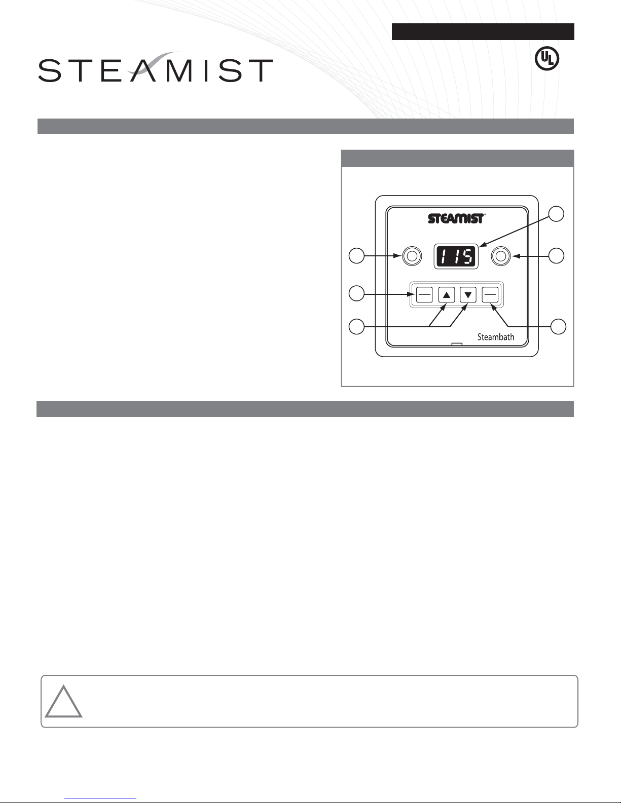
START
STOP
TIME
TEMP
SENSOR HEAT
2
1
6
TIME / TEMP
4 5
Installation and Operating Instructions
C US
®
02/09 Pub. No. 120-F
- 1 -
Control Features
1. Temperature Sensor: Measures temperature inside
steamroom.
2. Temperature/Timer Display: Counts down remaining
minutes and shows programmed minutes, set temperature,
and room temperature.
3. Heat Light: Indicates the generator is producing steam when
illuminated. The heater in the generator and the heat light
will cycle ON/OFF as the temperature is maintained
automatically in the steamroom.
4. Increase/Decrease, Temperature and Timer Set Keypads:
Press for a second to view the previously selected time/temp.
Press and hold to program the desired minutes or setpoint
temp.
5. Start/Stop Keypad: Press to start programmed cycle, press
again to cancel cycle.
6. Time/Temp Keypad: Press to select between time and
temperature.
Steambath Control
Installation Instructions
Model: DSC-425
DSC-425 Digital Timer and Digital Temperature Control
IMPORTANT: This control MUST be installed inside the steam-
room for proper operation of the system.
The Digital ON/OFF Elapsed Timer/Temp Control is designed
to be connected and operated only with the Steamist SM
Steambath Generator and cannot be used with any other
equipment.
CAUTION: All electrical connections must be performed by a
licensed electrician in accordance with Local and National
Electrical Codes. Power must be OFF until all wiring is complete.
1. Remove the cover from the Steambath Generator. Insert
multi-conductor cable with strain relief (provided) through
cabinet knockout and secure the cable to the top of the
steambath generator leaving 8" of cable inside the generator.
Remove the protective covering labeled “Remove Before
Installation” from the Telco Jack found on the Circuit Board.
Remove protective cap from plug and insert Steamist cable
into Telco Jack; check that the orientation of the plug properly
aligns with the jack. A snap will indicate the plug is installed
correctly (see Figure 1). Close and secure Generator cover.
NOTE: The DSC-425 Control should be stored in the
protective box until the wall is completed and is ready
to be installed.
2. Select a mounting location inside the steamroom for the
DSC-425 Control, 4 feet above the floor, convenient to
the bather. Do NOT locate in direct line of shower head
spray or above steamhead (see Figure 6). Mount 2
metal, gangable switch boxes, twinned together (not
provided) in this location. Do NOT use a 4x4 electrical
box.
WARNING: Elderly persons, pregnant women, or those suffering from heart disease, high blood pressure, diabetes, or
who are otherwise not in good health, do not use this device unless directed to do so by a physician. Also, do not use
steambath while under the influence of alcohol. For additional Important Safety Information, please see a separate
instruction sheet Pub. No. 199.
!
IMPORTANT: The DSC-425 Controls will only function with one of the following Steamist Generator models: SM-46, SM-79, SM-4,
SM-5, SM-7, SM-8, SM-11, SM-12, SM-15, System-18, System-24, System-30, with or without the InstaMist feature.
®

Protective Covering
“Remove Before
Installation”
Modular Jack Plug
Knockout for
Strain Relief
To Control
¾" Conduit
Coupler
Gasket
Control Cable
to Generator
Installation and Operating Instructions
IMPORTANT: Test Control for operation before installing
face plate.
6. To install Face Plate, peel back the (2) paper liners on
Base Plate to expose adhesive surfaces. Attach Face
Plate to the control.
7. Clean the face and Base Plate Assembly with a damp
cloth after installation to remove all dust, dirt, grime, etc.
Figure 1 Model: DSC-425
Figure 2 - Back of Control
02/09 Pub. No. 120-F
- 2 -
3. Carefully route the other end of the multi-conductor control
cable from the Steambath Generator to the DSC-425 inside
the steamroom. Route multi-conductor cable through a ¾"
conduit to protect the cable from damage and to facilitate
replacement if necessary.
4. Using the knockout either on top or bottom of the switch box,
secure cable with a strain relief fitting (provided). It is
suggested that the strain relief fitting be installed from inside
the switch box so cable may be adjusted. Allow approximately
10" - 12" of cable to extend into the box beyond the strain relief
fitting. Protect control cable by placing it inside the switch box
during construction, with the protective cap installed over the
end (see Figure 3).
5. After the walls are finished you are now ready to wire and
install the DSC-425 Control Digital On/Off Elapsed
Time/Temp.
CAUTION: Electrical Power to the Steambath Generator must be
OFF before making connections.
a) Locate Telco Jack at female coupler, on back of control.
Remove the protective covering labeled “Remove Before
Installation.” Remove protective cap from cable and plug
into jack. Check that the orientation of the plug properly
aligns with the jack. A snap will indicate the plug is installed
correctly (see Figure 2).
b) Mount Base Plate Assembly to the switch box using No.
6-32 x 2" S/S SCREWS (supplied in the plastic mounting
hardware bag).
IMPORTANT: DSC-425 Control MUST be mounted inside
the steamroom. Silicone sealant (supplied) MUST be used
to form a watertight seal to the wall.

Face Plate
Base Plate
#6-32 x 2" Long
Stainless Steel
Screw, 4 Places
Double-Sided
Adhesive Tape
2 Places
Reverse
Strain Relief
Coupler
IMPORTANT: Run the Control Cable through a ¾" Conduit.
To Generator
ENOCILIS
RAELC
.
ZO
.
LF2
/
1t
e
N02
5
13
.
o
N
me
t
I
.
A
.S.
UNI
EDAM
1/2"
Aromatherapy
Reservoir
Back Plate
O-Ring MUST
seal to inside of
the Back Plate
Cover Plate
Center Hub
3/4" NPT
(Brass Pipe)
Must use
sealant tape
Apply silicone around
the back edge of Back
Plate to seal and
prevent movement
3/8" Hex Key
Hole
Apply silicone
around the steam
pipe to form a
watertight seal
Apply a small amount
of silicone to prevent
movement IMPORTANT:
Install top first
MUST be vertical
After inserting the top,
snap in the bottom
Figure 5
the steamhead O-ring is fully seated into the Back Plate. If
the nipple is sticking out too far the O-ring will not make a
proper seal and the nipple must be adjusted.
5. Apply a small amount of silicone at the back center point of
the Cover Plate. This will aid in preventing movement of
this plate (see Figure 5).
6. Place the Cover Plate over the Center Hub. This is
accomplished by first hooking the top and then snapping
the bottom into place.
7. Adjust the Back Plate and Cover Plate to line up squarely,
and clean excess silicone with rubbing alcohol.
Installation and Operating Instructions
Figure 3 Model: DSC-425
02/09 Pub. No. 120-F
- 3 -
IMPORTANT: Apply Silicone around the edge of the control to
form a watertight seal to the wall (see Figure 4).
Cleaning Instructions: Use a damp cloth and mild soap. Do
NOT use abrasive cleaners which might scratch the surface or
the base of the control.
Installation Instructions for Steamhead & Center Hub
1. Make sure the 3/4" nipple protrudes beyond the tile
approximately 1/2" (see Figure 5).
2. Wrap the nipple with pipe sealant tape.
3. Put a bead of silicone around the outer edge of the Back
Plate (see Figure 5) and center the Back Plate over the
pipe in an upright position. While holding it in place screw
the Center Hub onto the nipple, using a ⅜" Hex Key to
tighten.
4. The Center Hub MUST be aligned with the four walls in the
vertical and horizontal position (see Figure 6). Make sure
Figure 4

All Instructions must be given to the homeowner for future use.
START
STOP
TIME
TEMP
SENSOR HEAT
Typical location of the DSC-425
Control. Locate away from the
direct line of shower spray and do
NOT locate above steamhead.
Steamhead Installation
Steamhead should be mounted 18"
above the finished floor or 6" above
the rim of the tub as far from the
bather as possible
Installation and Operating Instructions
IMPORTANT: Although the control is low voltage, power to the
generator must be switched off before servicing electrical
connections.
Operation: Simply press the Start/Stop keypad to begin the
previously programmed cycle. Pressing the Start/Stop keypad a
second time will cancel the cycle. After a cycle is started it will
take a few minutes for the Steam Generator to heat up and begin
producing steam.
During operation the display will flash between the remaining
time for 15 seconds and the ambient temperature for 45
seconds. A colon (:60) is displayed to indicate time, and no colon
indicates temperature. The heat light will cycle on and off as the
temperature is maintained.
Programming: There are several ways to program this control.
Adjustments can be made while the system is active and while it
is off. At any time the time or temperature is displayed, it can be
Operating Instructions
Additional Features
Model: DSC-425
Figure 6
02/09 Pub. No. 120-F
- 4 -
adjusted by simply pressing the Up or Down keypad. To
display the time or temperature, press the Time/Temp
keypad once or twice until it shows the setting to be
changed. All changes made to the temperature control are
stored in permanent memory until changed again. The
temperature range is 50° to 130°F (10° to 55°C). The timer,
however, has both temporary and permanent memory. Any
adjustments made to the timer while the system is active
will be stored in temporary memory for that cycle only. Any
adjustments made to the timer while the system is off are
stored in permanent memory. The temporary memory
allows you to make adjustments to the time in accordance
to your needs for that day without affecting the permanently
stored time. The timer range is from :01 to :60 minutes
Cleaning Instructions:
Use a damp cloth and mild soap.
Do NOT use abrasive cleaners which might scratch the
surface or the base of the control.
Memory: The memory for both the time and temperature is
retained even if there is a power failure.
Fahrenheit/Celsius: The temperature display may be changed
to Fahrenheit or Celsius by simultaneously pressing and holding
the Up and Down keypad for 5 seconds while the system is off.
The display will show the current setting “F” or “C” and then
alternate when the change is complete.
Error Messages:
This control is programmed with a diagnostic
feature to help isolate any potential problems. Error messages
E0, E1, E2 and E3 indicate a problem internal to the
control. If this occurs, the contorl must be replaced or
repaired. Error messages E4, E5 and E6 indicate a
communication problem with the Steam Generator. If this
error occurs, check both ends of the control cable for clean,
dry and secure connections. Dirty contacts can be cleaned
with alcohol and a cotton swab or a toothbrush. This can
also happen if the control is not sealed and the cable
connections get wet.
East Coast Office: 25 E. Union Ave., East Rutherford, NJ 07073 • Tel: 800-577-6478 • Fax: 201-933-0746
West Coast Office: 315 W. Pondera St., Suite F, Lancaster, CA 93534 • Tel: 800-355-6478 • Fax: 661-940-1617
®


