steel I9C-4 User manual

INSTRUCTION MANUAL
Gas barbecue for outdoor use

Thank you for choosing a first class product, which hopefully will
provide you with lots of pleasure in the future. Our ambition is to
offer a wide variety of quality products that make your life more
comfortable. Please take a few minutes to study this manual so that
you can take advantage of the benefits of your new machine. We
promise that it will provide a superior User Experience delivering
Ease-of-Mind.
The following symbols are used in this user manual:
Important information concerning your personal safety and
information on how to avoid damaging the appliance.
General information and tips.
Environmental information.
This appliance complies with:
Low Voltage Dir. 73/23/EEC.
Gas Dir. 90/396/EEC.
EMC Dir. 89/336/EEC.
CE Marking Dir. 93/68/EEC.
SQS-COC-100159
FSC Trademark 1996 Forest Stewardship Council A.C

General safety guidelines A
Gas safety guidelines A
Proper use B
Ecological disposal B
Dimensions 1
Examples of use 1
Preliminary operations 2
Connecting the gas bottle (category ii2H3+) 2
Table of characteristics 3
Check for gas leaks 3
General instructions about gas connection 3
Description of the barbecue 4
The control panel 4
Burner control knob 4
Description of symbols 4
Lid 5
Work surfaces 5
Assembling instruction 5
Wheel-mounted bottle trolley 6
Fitting and using the wheels 6
Adjusting the door 6
Adjustment of the drawer height 6
Utensil holder 7
Protection cover 7
Extractable basket 7
Assembling the ceramic tiles kit 8
8
Positioning the internal components 8
Positioning the grills and griddles correclty 9
Lighting the burners 10
Skewer 10
Cooking tips 11
Meat and Fish 11
Vegetables 11
Pots and pans 11
Brief cooking tips 11
Burner use table 11
Cleaning the barbecue 12
Stainless steel 12
Enamelled cast iron grills and griddle 12
Maintenance of the teak wood 12
Burners 12
Disassembling the burners 12
Drip pan 13
Contents

General informations
This appliance is designed to be used in the home and in the
open air.
The use in a professional setting or any other use considered
improper cause the immediate decline of the guarantee. The
appliance meets the conformity requirements of current EC
standards.
This manual is an integral part of the purchased product. it
should be preserved for the product's entire lifespan. Before
using the product, we recommend carefully reading this
manual and all the instructions it contains. These instructions
are valid solely for the countries the symbols of which are
shown on the cover page.
The appliance must be installed by qualified personnel in
accordance with current regulations.
This appliance must be installed by an authorised person in
accordance with this instruction manual, AS/NZS 5601.1 – Gas
installations (installation and pipe sizing) and local gas fitting
regulations.
The manual is divided into four sections:
Warnings
General regulations regarding the safety of operators and
correct appliance use.
Installation
instructions for the qualified technician in charge of installing,
commissioning and testing the appliance.
Use
Description of controls, switching on the appliance, fitting
accessories and cooking tips.
Cleaning and Maintenance
Recommended cleaning procedures and useful advice for
ensuring the appliance continues to work efficiently and look
good over time.

General safety guidelines Gas safety guidelines
Do not leave packing residue unattended around the home.
Separate out the various waste materials and take them to
the nearest recycling centre.
The identification plate, with the technical data, serial
number and mark, is clearly visible inside the bottle
compartment. The plate must never be removed.
Installation and servicing should be carried out by qualified
personnel in accordance with current regulations.
Before operating the appliance it is essential to remove the
protective film from the interior and exterior.
Immediately after installation, test the appliance briefly using
the directions for use. If it fails to work, contact your nearest
technical service centre. Never attempt to repair the
appliance.
Always wear protective gloves while handling particularly
hot components.
Some accessible parts can become very hot. Keep out of
reach of children.
If you smell gas: shut off the burner flames; close the valve
on the LPG bottle or the methane gas tap. If the smell
persists, contact your authorised service centre.
Never use flame to find gas leaks.
The gas pipe should be connected up to standard, and
should comply with current regulations that envisage the
installation of a safety tap upstream of the gas connection.
This appliance is fitted with gas safety valves. Do not
leave it unattended while it is in operation. should the
flames accidentally go out, turn the knobs immediately to
OFF and wait a few minutes before attempting to switch
on again.
The barbecue can only be used in the open air with natural
ventilation, outside of enclosed areas, where any gas leaks
and flue gases can disperse rapidly on the wind and with
natural air convection.
Do not use the barbecue in enclosed spaces, inside
camper vans, caravans or any other mobile installation.
Never use this cooking device to heat rooms.
Never rest inflammable objects on the appliance: this may
result in a fire if the appliance is switched on.
This appliance is manufactured to use Methane. Should it
be necessary to use another type of gas (LPG) contact your
nearest authorised centre.
Always handle empty gas bottles with care and in
accordance with the safety regulations provided with the
relative instructions. Do not use gas bottles that are dented
or rusty.
Do not store spare gas bottles close to the barbecue.
Never disconnect the bottle from the barbecue while it is in
operation. Always stand well away from the appliance for
any operation to do with the gas bottle.
Only use the unions and regulators supplied with the
appliance to connect to the bottle.
After the appliance has been unused for a time, always
check the gas is correctly connected before switching on
again (see section "Check for gas leaks" on page 3) and
check that the gas outlet holes are not clogged with dust or
the like (see section "Burners" on page 12).
WARNING - This barbecue must not be used indoor
Warnings
A

BWarnings
Proper use Ecological disposal
The appliance is designed to be used by adults only. Do not
allow children to approach the appliance or use it as a toy.
Never leave the appliance unattended during use.
The pans and containers used on the grills must have a
perfectly flat, smooth bottom.
Do not use containers that protrude over the outer
perimeter of the surface.
Switch on the burners only when the lid is lifted.
Before the barbecue is first used for cooking, the burners
should be left on for 10 minutes (with the lid up) to burn off
all manufacturing residue and oil.
Always open the lid before switching on the barbecue. Never
close the lid before the barbecue has cooled down.
The barbecue becomes very hot during use. To avoid being
scolded, it is advisable to wear heat protection gloves. Do
not touch the heating elements inside the appliance.
After each use, always check that the control knobs are set
to OFF.
Do not use the barbecue in bad weather. Contact with
water can severely damage the appliance and endanger
its safety.
Do not obstruct the vents of the appliance.
To prevent the combustion of previous cooking residue,
clean the drip pan, burners compartment and the burners
themselves before each use.
Do not use metal sponges or sharp scrapers on the external
surfaces. Use normal non-abrasive products, with wooden or
plastic utensils if necessary. Rinse thoroughly and dry with a
soft cloth. Do not use high pressure water jets on the
barbecue, the power of the water jet may damage the finish
and endanger safety.
If you foresee to let your barbecue unused for a long
period, make sure it is appropriately cleaned, see the
chapter about "Cleaning the barbecue" at page 12; put on
the protection cover and place the appliance in a sheltered
location.
The product packing is made of non-polluting, environment
friendly and recyclable materials. Dispose of the packing
correctly at recycling and disposal centres.
The manufacturer declines all responsibility for use other than
that indicated, as well as for damage to things or harm to
persons caused by failure to comply with these guidelines or
by tampering, even partially, with the appliance or by the use
of non-original spare parts.

Dimensions
Top Version
Installation 1
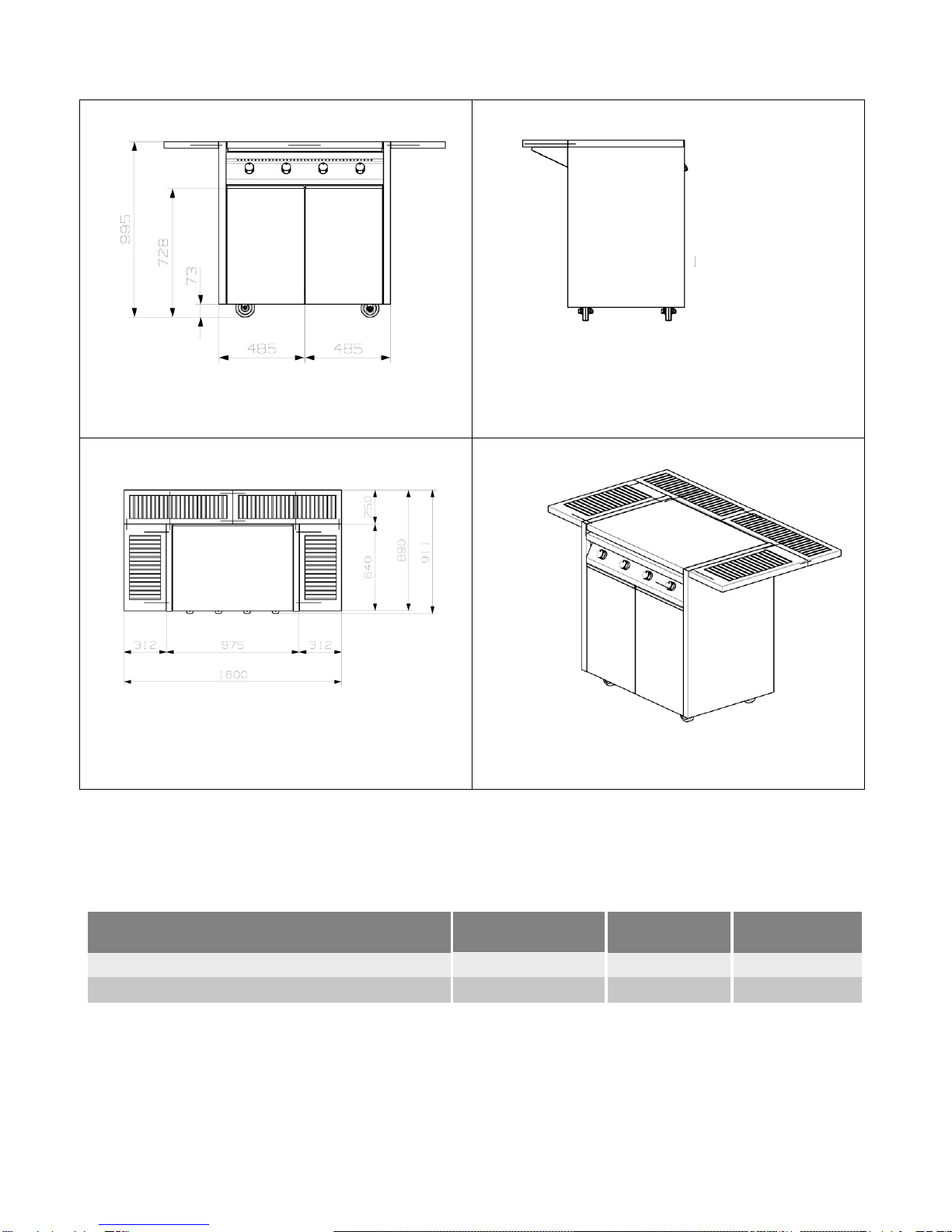
Version with trolley and side shelves
MODEL NO. BURNERS X Y
I 9 C - 4 4 1 6 0 0 9 7 5
I 7 C - 2 2 1 3 0 0 8 5 0

Types of installation
Built-in installation
DO NOT USE THE BARBECUE IN THE TOP VERSION
WITHOUT FITTING THE FOOT FIRST. Place the top on a flat
surface and ensure it is stable by tightening the foot adjustment
screws.
The barbecue may be installed free standing, on a
metal shelf or built into a brick structure. In any case,
the following guidelines must be followed.
Leave a gap of at least 5 cm from the side walls and any
back wall. In built-in installations the adjacent walls must
not be higher than the work surface of the barbecue. If an
additional top is installed, it must be at least 1 m higher
thanthebarbecuegrills.
SMALLER DISTANCES THAN THOSE INDICATED MAY
CONSTITUTE A RISK FOR THE USER'S SAFETY AND
DAMAGE THE STRUCTURE OF THE BARBECUE.
This appliance must be installed by an authorised person
in accordance with this instruction manual, AS/NZS 5601.1
– Gas installations (installation and pipe sizing) and local
gas fitting regulations.
LPG: the supplied hose and regulator mustbe fitted to
the appliance inlet connection. Gas pressure is 2.75 kPa.
The isolating manual shut-off valve connection point
must be accessible when the appliance is installed.
The hose assembly must not be subject to strain,
abrasion, kinking or deformation and must not be in
contact with the floor or any hot or sharp surfaces.
Minimum LPG cylinderis 4.5 kg and the maximum LPG
cylinder is 9.0 kg
Natural Gas: the supplied regulator must be fitted to
the appliance inlet connection. Gas pressure must be
adjusted to 1.0 kPa when approximately 50% of the
burners are on high flame; the appliance test point is
located on the regulator.
Suitable for connection with rigid pipe or flexible hose.
The isolating manual shut-off valve connection point
must be accessible when the appliance is installed.
Flexible hose must comply with AS/NZS 1869 Class B or
D,be of appropriate internal diameter for the total gas
consumption, be kept as short as possible
(not exceeding 1200mm), must not be in contact with
the floor or any hot or sharp surfaces. The hose
assembly must not be subject to strain, abrasion,
kinking or deformation.
If applicable, a restraining device must be fitted to
9
Installation
UK

restrict the appliance movement to no more than 80%
of the gas hose length.
Only use a licensed gasfitter to install this barbecue and
other trades as applicable; builder or bricklayer.
The operation of the appliance must be tested by the
installer to confirm all burner flames are blue in colour,
stable and completely ignite at both high and low flame
settings with no appreciable yellow tipping,
carbon deposition, lifting, floating, lighting back or
objectionable odour. Test burners individually and in
combination
Tableofburners,injectorsizesandgas consumption
characteristics

Free standing installation
The Barbecue must be located away from surrounding
surfaces and combustible materials. Minimum clearance
is 250mm from the sides, 250mm from the rear and 1000mm
overhead.
This appliance must be installed by an authorised person in
accordance with this instruction manual,
AS/NZS 5601.1 – Gas installations (installation and pipe sizing)
and local gas fitting regulations.
Gas inlet is located at the front right hand side 100mm from
the side edge.
LPG: the supplied hose and regulator must be fitted to the
appliance inlet connection. Gas pressure is 2.75 kPa.
The isolating manual shut-off valve connection point must be
accessible when the appliance is installed.
The hose assembly must not be subject to strain, abrasion,
kinking or deformation and must not be in contact
with the floor or any hot or sharp surfaces.
Only use a licensed gasfitter to install this barbecue and other
trades as applicable; builder or bricklayer.
The operation of the appliance must be tested by the installer
to confirm all burner flames are blue in colour, stable and
completely ignite at both high and low flame settings with no
appreciable yellow tipping, carbon deposition, lifting, floating,
lighting back or objectionable odour. Test burners individually
and in combination.
Minimum LPG cylinder is 4.5 kg and the maximum LPG
cylinder is 9.0 kg
The outdoor area in which the barbecue is positioned must
meet the following requirements:
1. there may be walls on all sides, but there must be at least
one permanent doorway and no ceiling;
2. there may be no more than two side walls when there is a
ceiling;
3. there may be partial overhead cover, including a ceiling, but
with no more than two walls and with the following
conditions:
a) At least 25% of the total wall surface is completely
open.
b) At least 30% of the remaining surface is open and not
delimited.
If positioning on a balcony or terrace, at least 20% of the total
wall surface must be open.
1 2 3
3a
3b

Installation
Preliminary operations
The barbecue has been designed and built to cook and heat food in
the open air. This appliance is not designed for use in a professional
setting or in enclosed spaces.
Before installing and using the barbecue, the interior should be
cleaned of any manufacturing residue. For further information on
cleaning referto chapter "Cleaning the barbecue" on page 12.
Choose the installation site for the barbecue carefully:
1. it must not be too dusty: long term dust may clog the
burners and make using the barbecue hazardous;
2. it must not be too exposed to the wind: during use strong
winds may prevent the barbecue from working properly or
accidentally switch off the burners;
3. position the barbecue so that it is completely stable;
4. away from inflammable materials.
Before installing and using the barbecue remove all plastic transit
protections from the control panel and from the stainless steel
sides of the appliance.
Connecting the gas bottle (category II2H3+)
The appliance is already regulated to operate with LPG (G30/31 at
28-30/37mbar). Simply connect the rubber pipe using the seals and
clamps supplied as described below.
Remove the lower rear panel "F": pull it up and ahead.
Remove the upper rear panel "G": pull it up and ahead.
Provide a gas pipe of 800 mm length. You may need a pipe
holder "H" on the end of the ramp "E".
Connect the end "A" of the gas pipe directly to the ramp "E"
or to the pipe holder "H".
Connect the end "I" of the gas pipe to the pressure
regulator "C".
Connect the gas pressure regulator "C" to the threaded
union "B" on the bottle.
When the gas bottle is inside the chart make the gas tube
going trough the hole "D" then connect.
Fit the rear panels "G" and "F" putting in position then
pulling down.
The symbols in the picture mean that on those points a
clamp could be necessary.
After connecting, ensure the rubber pipe is not crushed, hanging
or obstructing the hole in the lid.
Contact your nearest authorised service centre to connect
the barbecue to a methane supply (G20 at 20 mbar).
Refer to current regulations to fit or replace the rubber pipe.
The pipe's expiry date is printed on the pipe itself. Ensure the
pipe is replaced before this date.
Should the gas bottle not be fitted with a stop valve, a shut-off tap
should be used. The tap must be easily accessible.
Do not obstruct the vents in the bottle compartment. The gas bottle must
be replaced away from any power source.
B
C
I
A
H
G
F
E
D

Table of characteristics for single burner
BURNERS GRILL
Rated power k W 6 . 2 0
Reduced power k W 2 . 2 0
CONSUMPTION
G20 20mbar
m
3
/ h
0.590
G30 28..30mbar
g / h
450.82
G20 2.75kPa
g r / h
450.82
NOZZLE DIAMETER
G30 28..30mbar
G31 37mbar
n °
127
G30 50mbar G31 50mbar n ° 1 1 0
G20 20mbar n ° 1 9 0
G20 1.0 kPa n ° 2 2 0
G30 2.75 kPa n ° 1 4 0
BY-PASS DIAMETER
G30 28..30mbar G31 37mbar n ° R e g .
G30 50mbar G31 50mbar n ° R e g .
G20 20mbar m m R e g .
G20 1.0 kPa m m R e g .
G30 2.75 kPa m m R e g .
Check for gas Ieaks
This check should be carried out immediately after connecting the gas and
each time the appliance is reconnected after being unused for a time. Once
the rubber pipe is connected to the gas supply, carry out the following
operations:
1. Open the gas valve on the LPG bottle (or turn the shut-off
tap if methane supplied).
Do not light the burners yet.
2. With the gas pressure in the pipe, look for any leaks by
brushing a soapy water-based solution onto the gas
unions. A gas leak will cause bubbles to form.
Do not use naked flame to look for leaks.
4. Close the gas valve on the bottle (or the methane shut-off
tap), eliminate the gas leak and repeat the test as described in
points 1 and 2.
The fittings must be thoroughly rinsed with clean water after
testing.
Installation 3
General instructions about gas
connection
We recommend checking that the appliance
is properly set up for the type of gas
distributed. The connection to the gas pipes
must be made in a workmanlike manner, in
compliance with current standards that prescribe the
installation of a safety tap at the end of the pipe. The threaded
1/2" gas connection pipe is located at the rear on the left hand
side of the appliance.
Using flexible rubber pipes with a max. length
of 1500 mm:
do not allow the pipes to be constricted or
crushed;
pipes must not be subject to tractive force or
torsional stress;
do not allow the pipes to come into contact
with cutting or sharp edges, etc...
do not allow the pipes to come into contact
with parts that can reach temperatures of
70°C above room temperature;
make sure the entire length of the pipes can
be inspected.
1/2”

4Installation
The control panel
All the barbecue's controls are fitted on the front panel.
1 Left burner control knob
2 Centre left burner control knob
3 Centre right burner control knob
4 Right burner control knob
1 2 3 4
Burner control knob
To switch on the burner refer to section "Lighting the
burners" on page 10.
Descriptionofsymbols
Piezoelectric ignition
Maximum flame
Minimum flame
Burner off
A Side work surface
BDrip pan
C Exhaust vents
DEnamelled cast iron grills
E
Griddle
Description of the barbecue F Drawer
GGas bottle compartment door
HControl knobs I
Wheel with brake
L Wheel without brake
M Lid
A
M
B
C
B
F
G
I
L
E
D
H

Lid
Always open the lid before switching on the barbecue. Never
close the lid before the barbecue has cooled down.
The lid becomes hot while cooking.
To prevent from damaging the lid and wooden sides:
Opening:
Pull u p t he lid an d l e t it slid e t o th e rear; w h e n
in v e rt i c al po sition l e a v e i t o n t he rubb e r s .
Clo s in g :
Pull up the lid to the front side and leave it only when it is
completely out.
Work surfaces
TEAK work surface. It is fastened to the barbecue structure.
The Work surfaces are designed to withstand a maximum weight
of 10 Kg.
Assembling instruction
1. Insert the washer "A" into the pins "B".
2. Insert the pins "B" into the holes "C".
3. Fix the screws "D" to the pins "B".
4. Fix the supports "E" to the washers "F" and the screws "G"
to the pins "H".
5. Insert the pins "I" into the holes "L".
6. Insert the sides "P" into their own pins.
7. Fix the sides supports to the rear wooden by turning the
hooks "M".
B
Installation
5
P
H
F
L
G
D
M
I
C
A
E
P
P
P

6Installation
Wheel-mounted bottle trolley
Made of stainless steel 18/10. Fitted with two fixed wheels
and two pivot wheels with brake. Designed to contain the
gas bottle, but can also be fitted with drawers or additional
cupboards depending on the width.
Bottles up to 50 cm tall (including the fitted pressure
regulator) can be stood under the trolley surface. It is
advisable to fit the pressure regulator outlet horizontally.
The drawers are designed to withstand a maximum weight of 25 kg.
Do not rest inflammable objects (such as paper, cloth and other
materials) inside the drawers or inside the bottle compartment.
Fitting and using the wheels
The wheels provided with brakes must be fit on the left of the
appliance, while the other wheels must be fit on the right side.
To fix the brackets of the barbecue simply press a foot onto the
snap lever as shown in the figure. To release the brackets,
return the lever to standby position.
Do not use the trolley unless the wheels are correctly screwed in.
Adjusting the door
The hinge on the door can be adjusted by turning the screws
indicated by the arrows in the adjacent diagram.
Adjust the door once installation is complete.
Adjustment of the drawer height
The clips of height adjustment are located in the lower side
and at the right and left ends of the drawer.
By turning the lever "A" the drawer will raise of 3 mm.
LEFT
RIGHT
C
A
+ 2,8 mm
+2
B
-
2
A
+3mmmax

Utensil holder
The utensil holder is a steel frame for storing utensils and
tools inside the gas bottle compartment.
To fit the holder, proceed as follows:
open the door of the gas bottle compartment;
place the frame onto the 4 fastening pins ,.A„already
secured to the inside of the door;
p u s h t h e f r a m e d o w n w a r d s u n t i l t h e p i n s
f i t i n t o t h e s l o t s , . B„. T o r e m o v e t h e f r a m e ,
l i f t u p w a r d s t h e n a w a y f r o m t h e p i n s .
Protection cover
PVC waterproof plastic material, to be used for covering and
housing in the open air the barbecue in the trolley version. To
clean use water and neutral detergent.
Extractable basket
The 70 cm version is equipped with an extractable basket.
When fully open, the basket can withstand up to 15 Kg. Do not
exceed this limit to avoid damaging the basket.
Installation
7
B
B
A
A

8U s e
Assembling the ceramic tiles kit
1. Remove the grill grates "A", griddles "B" and disperser "C"
(one per kit to be installed).
2. Place the two side supports "D" and the central support "E"
(for double kit only) in the combustion chamber.
3. Position the crosspieces "F" in the slots made in supports "D"
and "E".
4. Rest the tiles on the frame as shown in the figure.
5. Replace the grill grates "A" and griddles "B".
The disperser "C" (one per kit) is not replaced, as it would not fit
with the tiles assembled.
To assure a good working, take care that the ceramic tiles holes
get not obstructed. Overturn the tiles regularly to let the burners
carbonate the cooking residuals.
Positioning the internal components
Before beginning to cook, check the burners, dispersers,
deflectors, grills and griddle are correctly in place.
The figure shows the correct sequence for positioning the
burners "A", dispersers "B", deflectors "G", grills "C", the grids
"D" and the ceramic tiles frame "F".
The tabs on the dispersers "B" should be inserted into the slots
"E" on the inside of the barbecue.
Only in the conditions illustrated above, with all the aforesaid
components correctly assembled, is it advisable to start
cooking. Any other set-up may constitute a risk for the user
F
D
F
F
D
D
E
D
F
C
A
B
E
G
A
B
D
C
F

and may jeopardise the good use of the appliance.

Closed griddle, flat side
U s e 9
Positioning the grills and griddles correclty
To ensure the best grill result it is important to select the most
appropriate griddles for the type of food to be cooked. Below
are some hints listed.
Fillet steaks
Fish
Shrimps
Chicken legs
Vegetables
Sausages
Cheese
Fruit
Hamburgers
Vegetables
Cheese
Fried eggs
Bacon
The open griddles can be used on both sides. The closed
griddles are double-faced: smooth on one side, striped on
the other side, in order to allow different kinds of cooking.
Never put the two griddles side by side. For a correct positioning and
use please refer to the below diagram.
pen griddle
Closed griddle, ribbed side
This manual suits for next models
1
Table of contents
Popular Grill manuals by other brands

Monument Grills
Monument Grills 13742 Assembly & operating instructions

Superior
Superior JA802 T-1A user manual

Landmann
Landmann "Grill-Lok" 11094 Assembly instruction

Vermont Castings
Vermont Castings Signature VCS5037 User's manual & assembly

Adexa
Adexa KLG 230-HG Operation manual

GAS ONE
GAS ONE GP-1040 Operation manual


