OPERATING INSTRUCTIONS
5
Before You Start - Safety
• Always wear eye protection that complies with a recognized standard (for example: ANSI Z87.1)
- (CSA or ANSI).
• Wear a mask or respirator when dust is generated.
•Keep bystanders out of the work area while operating the tool.
WARNING! Always ensure that the work area is clear of any flammable
materials, liquids or gasses, because the use of this tool may create sparks.
Do not wear loose clothing or jewellery. Keep hair tied back.
WARNING! Replace cracked grinding wheels immediately.
Do not overtighten spindle nuts.
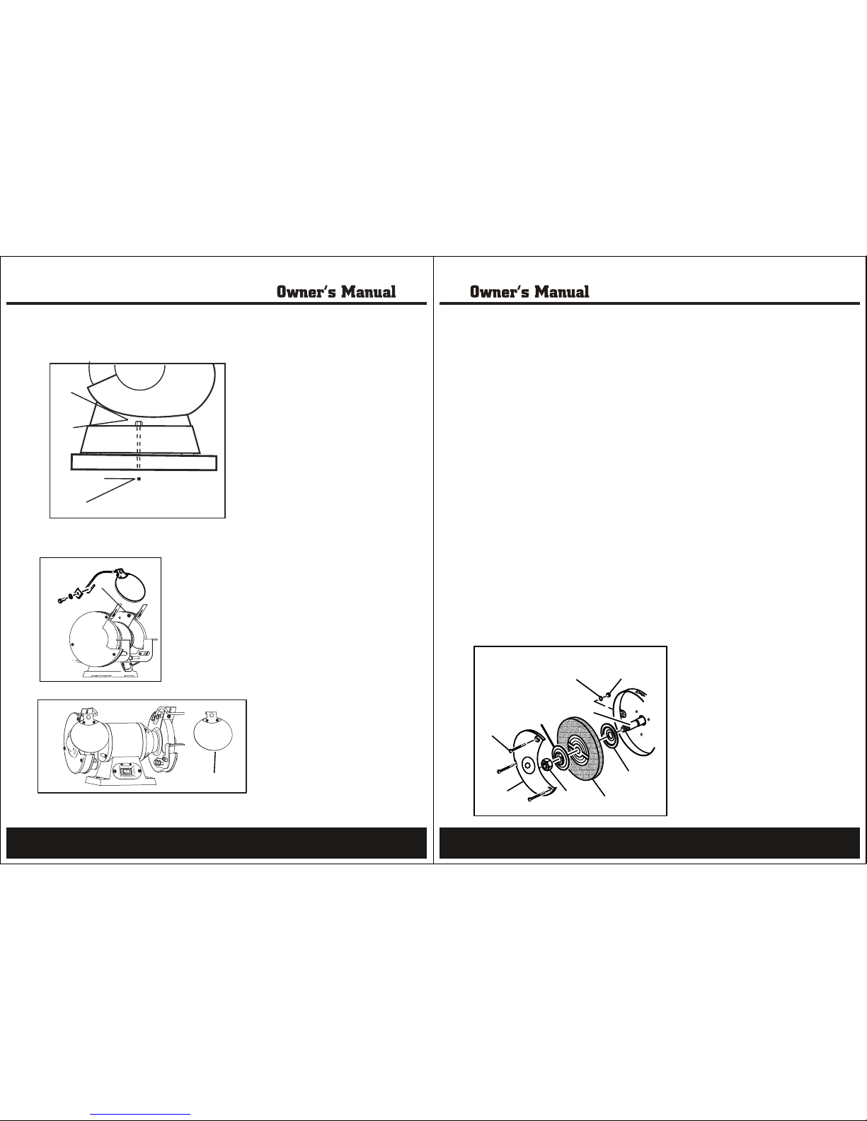
Adjust tool rests whenever necessary to maintain a distance of 1/8” (3.2 mm) from the
grinding wheel.
NEVER grind on the side of the wheel. Grind on the face of the wheel only.
NEVER apply pressure to the workpiece when the grinding wheel is cold. Allow the wheel to
warm up by applying the workpiece gradually.
NEVER use the grinder without the wheel guards. Keep thumbs and fingers away from the wheel.
Before You Start – Electrical
In the event of a malfunction or short circuit, grounding provides the path of least resistance for
electrical current, and reduces the risk of electric shock for the operator. This tool is equipped with
an electric cord that has an equipment grounding conductor and a grounding plug. The plug MUST
be plugged into a matching outlet that is properly installed and grounded in accordance with ALL
local codes and ordinances.
DO NOT MODIFY THE PLUG PROVIDED. If it will not fit the outlet, have the proper outlet installed by an
electrician.
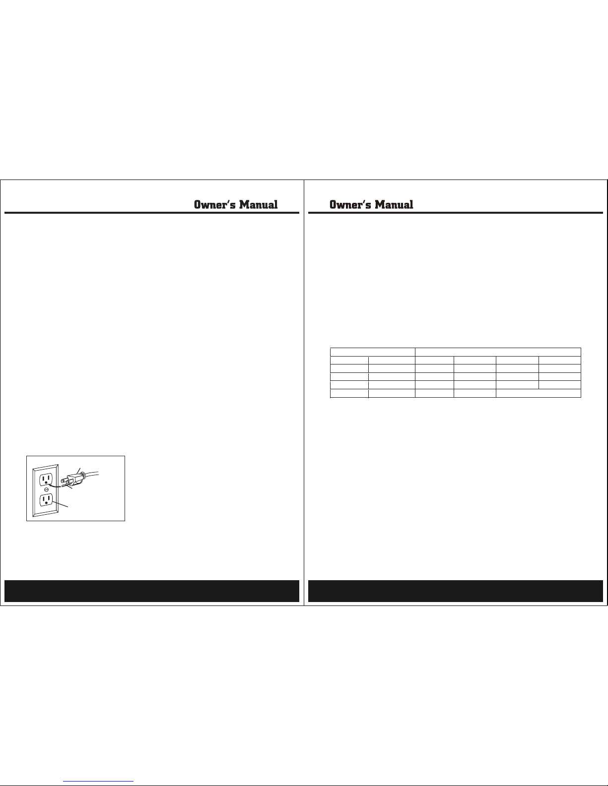
Figure 2
IMPROPER CONNECTION of the equipment ground conductor can result in increased risk of electric
shock. The conductor with the green insulation (with or without yellow stripes) is the equipment
grounding conductor. If repair or replacement of the electric cord or plug is necessary, DO NOT
connect the equipment grounding conductor to a live terminal.
CHECK with a qualified electrician or service personnel if you do not completely understand the
grounding instructions, or if you are not sure if the tool is properly grounded.
3-Pronged Plug
Properly Grounded
3-Holed Receptacle
Grounding Prong
6
This tool is intended for use on a circuit that has an outlet that looks like the one illustrated. The original
tool has a grounding plug that looks like the plug illustrated (Figure 2).
Use of Extension Cords
USE ONLY THREE-WIRED EXTENSION CORDS that have 3-pronged plugs and 3-holed outlets that
accept the tool’s plug. Repair or replace damaged or worn cords immediately.
Be sure your extension cord is properly wired and in good condition. Do not use damaged extension
cords. Always replace a damaged extension cord.
When using an extension cord, be sure to use one heavy enough to carry the current your product will
draw. An undersized cord will cause a drop in line voltage, resulting in loss of power and overheating.The
table below shows the correct size to use according to the cord length and the amperage draw of the tool
(specified on the nameplate). When in doubt, use the next heavier gauge. The smaller the gauge number,
the heavier the cord. (AWG = American Wire Gauge).
Minimum Gauge for Extension Cords (AWG)
Ampere Rating Total Length of Cord in Feet (meters)
(when using 120 volts only)
More Than Not more Than 25’ (7.6m) 50’ (15m) 100’ (30.4m) 150’ (45.7m)
0 6 18 16 16 14
6 10 18 16 14 12
10 12 16 16 14 12
12 16 14 12 Not Recommended
Use a separate electrical circuit for your tools. This circuit should not be less than a #12 gauge wire,
and should be protected with a 15 A time-lag fuse. Before connecting the motor to the power line,
ensure the switch is in the OFF position and the electric current is rated the same as the current stamped
on the motor’s nameplate. Running at a lower voltage will damage the motor, and this damage is not
covered by warranty.
Before You Start – Package Main Contents
Shield Rods – one left, one right……………....2
Carriage bolt………………..............................1
Hex head bolt……………….1
Washers……………….........2
Lock washer………………...1
Clamp bracket……………....1
Screw……………….............1
Work rest knob……………...1
Shield Rod Brackets with Hardware…………...2
Safety Shields…………………………………2
Spark Deflectors – one left, one right ………...2
Work rest – one left, one right………………..2
Before You Start – Assembly and Installation
Mounting the Grinder to the Workbench
Before attempting to use this grinder, it must be properly mounted to a workbench or grinding stand.
CAUTION!Bench grinders vibrate. Grinder movement during high-speed rotation may cause
injury or damage to the workpiece or operator. Mount the grinder securely to a sturdy workbench
or grinding stand.
1. Position the grinder on the workbench.
2. Mark the workbench through the two mounting holes located in the grinder base.