STEELE PRODUCTS SP-SB055E User manual

WARNING! To Reduce The Risk Of Injury, User
Must Read And Understand Instruction Manual.
Model: SP-SB055E
196cc Displacement
120V Electric Start
4 Cycle Engine
21 inch Single Stage
Auger Propelled
CAUTION: Before using this product,read
this manual and follow all of its Safety
Rules and Operating Instructions.
INTRODUCTION……………………………………………………………………………………………..……2
RESPONSIBILITY OF THE OWNER………………………………………………………………………..….2
RULES FOR SAFE OPERATION……………………………………………………………………….………3
MAINTENANCE AND STORAGE………………………………………………………………………………5
SYMBOLS…………………………………………………………………………………………….……..….....6
ASSEMBLY………………………………………………………………………………………………..………7
OPERATION..…………………………………………………………………………………………..………..10
MAINTENANCE………………………………………………………………………………………………….16
STORAGE…………………......................................... ……………….......................................................19
TROUBLESHOOTING…………………………………………………………………………………….……..20
PARTS …………………………………………………………………………………………………………….21
1
Congratulations on your purchase. This Snowthrower has been designed, engineered and manufactured to
give you the best possible dependability and performance. However, like all mechanical products, your
machine will occasionally require adjustment and maintenance. This handbook should be read before
operating or performing and adjustments on your machine.
The instructions in this Owner’s Manual are written for a person with some mechanical ability. Like most
service books, not all the steps are described. Steps on how to loosen or tighten fasteners are steps anyone
can follow with some mechanical ability. Read and follow these instructions before you use the unit.
Know your product: If you understand the unit and how the unit operates, you will get the best performance.
As you read this manual, compare the illustrations to the unit. Learn the location and the function of the controls.
To help prevent an accident, follow the operating instructions and the safety rules. Keep this manual for future
reference.
IMPORTANT: Many units are not assembled and are sold in cartons. It is the responsibility of the owner to
make sure the assembly instructions in this manual are exactly followed. Other units are purchased in an
assembled condition. On assembled units, it is the responsibility of the owner to make sure the unit is correctly
assembled. The owner must carefully check the unit according to the instructions in this manual before it is first
used.
The warranty, found in this manual, details the coverage and limitations of this product.
It is the responsibility of the owner to follow the instructions below.
1. Carefully read and follow the rules for safe operation.
2. Follow all the assembly instructions.
3. Inspect the unit.
4. Make sure that the operator of the unit knows how to correctly use all standard and accessory equipment.
5. Operate the unit only with guards, shields, and other safety items in place and working correctly.
6. Correctly adjust the unit.
7. Service the unit only with authorized or approved replacement parts.
8. Complete all maintenance on the unit.
2
LOOK FOR THIS SYMBOL TO POINT OUT IMPORTANT SAFETY PRECAUTIONS.
IT MEANS-- -- ATTENTION!!! BECOME ALERT!!! YOUR SAFETY IS INVOLVED.
WARNING: Engine Exhaust, some of its constituents, and certain vehicle components contain
or emit chemicals known to the State of California ˄USA˅to cause cancer and birth defects or other
reproductive harm.
Battery posts, terminals and related accessories contain lead and lead compounds, chemicals known
to the State of California˄USA˅to cause cancer and birth defects or other reproductive harm.
WASH HANDS AFTER HANDLING.
WARNING: Always disconnect the spark plug wire and place it where it cannot make contact
with spark plug to prevent accidental starting during: Preparation, Maintenance, or Storage of your
snow thrower.
IMPORTANT:Safety standards require operator presence controls to minimize the risk of injury. Your snow
thrower is equipped with such controls. Do not attempt to defeat the function of the operator presence control
under any circumstances.
WARNING: This snow thrower is capable of amputating hands and feet and throwing objects.
Failure to observe the following safety instructions could result in serious injury.
TRAINING
1. Read this operating and service instruction manual carefully. Be thoroughly familiar with the controls and the
proper use of the snow thrower. Know how to stop the snow thrower and disengage the controls quickly.
2. Never allow children to operate the snow thrower. Never allow adults to operate the snow thrower without
proper instruction.
3. Keep the area of operation clear of all persons, particularly small children and pets.
4. Exercise caution to avoid slipping or falling especially when operating in reverse.
PREPARATION
1. Thoroughly inspect the area where the snow thrower is to be used and remove all doormats, sleds, boards,
wires, and other foreign objects.
2. Disengage all clutches before starting the engine (motor).
3. Do not operate the snow thrower without wearing adequate winter outer garments. Wear footwear that will
improve footing on slippery surfaces. Avoid loose fitting clothing that can get caught in moving parts.
4. Handle fuel with care; it is highly flammable.
a. Use an approved fuel container.
b. Never remove fuel tank cap or add fuel to a running engine (motor) or hot engine (motor).
3

c. Fill fuel tank outdoors with extreme care. Never fill fuel tank indoors.
d. Replace fuel cap securely and wipe up spilled fuel.
e. Never store fuel or snow thrower with fuel in the tank inside of a building where fumes may reach an open
flame or spark.
f. Check fuel supply before each use, allowing space for expansion as the heat of the engine (motor) and/or
sun can cause fuel to expand.
g. Never fill containers inside a vehicle or on a truck or trailer bed with a plastic liner. Always place containers
on the ground, away from vehicle, before filling.
h. When practical, remove gas-powered equipment from the truck or trailer and refuel it on the ground. If this
is not possible, then refuel such equipment on a trailer with a portable container, rather than from a
gasoline dispenser nozzle.
i. Keep the nozzle in contact with the rim of the fuel tank container opening at all times, until refueling is
complete. Do not use a nozzle lock-open device.
j. If fuel is spilled on clothing, change clothing immediately.
5. Let engine (motor) and snow thrower adjust to outdoor temperatures before starting to clear snow.
6. Always wear safety glasses or eye shields during operation or while performing an adjustment or repair to
protect eyes from foreign objects that may be thrown from the snow thrower.
OPERATION
1. Do not operate this snow thrower if you are taking drugs or other medication which can cause drowsiness or
affect your ability to operate this snow thrower.
2. Do not use the snow thrower if you are mentally or physically unable to operate the snow thrower safely.
3. Do not put hands or feet near or under rotating parts. Keep clear of the discharge opening at all times.
4. Exercise extreme caution when operating on or crossing gravel drives, walks or roads. Stay alert for hidden
hazards or traffic.
5. After striking a foreign object, stop the engine (motor), remove the wire from the spark plug, thoroughly
inspect snow thrower for any damage, and repair the damage before restarting and operating the snow
thrower.
6. If the snow thrower should start to vibrate abnormally, stop the engine (motor) and check immediately for the
cause. Vibration is generally a warning of trouble.
7. Stop the engine (motor) whenever you leave the operating position, before unclogging the auger/impeller
housing or discharge chute and when making any repairs, adjustments, or inspections.
8. When cleaning, repairing, or inspecting, make certain the auger/impeller and all moving parts have stopped
and all controls are disengaged. Disconnect the spark plug wire and keep the wire away from the spark plug
to prevent accidental starting.
9. Take all possible precautions when leaving the snow thrower unattended. Disengage the auger/ impeller,
stop engine (motor), and remove key.
10. Do not start or run engine in enclosed area, even if doors or windows are open. Exhaust fumes are
dangerous (containing CARBON MONOXIDE, an ODORLESS and DEADLY GAS).
11. Exercise extreme caution if operating on steep slopping surfaces.
12. Do not clear snow across the face of slopes. Exercise extreme caution when changing direction on slopes.
Do not attempt to clear steep slopes.
13. Never operate the snow thrower without proper guards, plates or other safety protective
devices in place.
4
14. Never operate the snow thrower near enclosures, automobiles, window wells, dropoffs, and the like without
proper adjustment of the snow discharge angle. Keep children and pets away.
15. Do not overload the snow thrower capacity by attempting to clear snow at too fast a rate.
16. Never operate the snow thrower at high transport speeds on slippery surfaces. Look behind and use care
when backing up.
17. Never direct discharge at bystanders or allow anyone in front of the snow thrower.
18. Disengage power to the collector/impeller when snow thrower is transported or not in use.
19. Use only attachments and accessories approved by the manufacturer of the snow thrower (such as tire
chains, electric start kits, ect. ).
20. Never operate the snow thrower without good visibility or light. Always be sure of your footing and keep a
firm hold on the handles. Walk; never run.
21. Do not over-reach. Keep proper footing and balance at all times.
22. Do not use the snow thrower on surfaces above ground level such as roofs of residences,
garages, porches or other such structures or buildings.
23. This snow thrower is for use on sidewalks, driveways and other ground level surfaces.
24. Never touch a hot engine or muffler.
WARNING: This snow thrower is for use on sidewalks, driveways and other ground level
surfaces.
Caution should be exercised while using on steep sloping surfaces. DO NOT USE SNOW THROWER
ON SURFACES ABOVE GROUND LEVEL such as roofs of residences, garages, porches or other such
structures or buildings.
Clearing A Clogged Discharge Chute
WARNING: Hand contact with the rotating impeller inside the discharge chute is the most
common cause of injury associated with snow throwers. Never use your hand to clean out the
discharge chute. To Clear The Chute:
. SHUT OFF THE ENGINE!
. Wait 10 seconds to be sure that the impeller blades have stopped rotating.
. Always use a clean-out tool, not your hands.
1. Check shear bolts and other bolts at frequent intervals for proper tightness to be sure the snow thrower is in
safe working condition.
2. Store the snow thrower away from ignition sources or appliances that have a pilot light, such as hot water
and space heaters, clothes dryers, etc.... Allow the engine (motor) to cool before storing in any enclosure.
3. Always refer to operator’s guide instructions for important details if the snow thrower is to be stored for an
extended period.
4. Maintain or replace safety and instruction labels, as necessary.
5. Run the snow thrower a few minutes after throwing snow to prevent freeze-up of the auger/ impeller.
5
IMPORTANT: Many of the following symbols are located on your snow thrower or on literature supplied
with the product. Before you operate the snow thrower, learn and understand the purpose for each
symbol.
CONTROL AND OPERATING SYMBOLS
6
Safety Warning Symbols
References to the right or left hand side of the snow thrower are from the viewpoint of the operator’s position
behind the unit.
HOW TO REMOVE FROM THE CARTON
1. Locate and remove container of 5W30 oil.
2. Locate all parts packed separately and remove from the carton.
3. Remove and discard the packing material from around the snow thrower.
4. Cut down all four corners of the carton and lay the panels flat.
5. Hold onto the lower handle and pull the snow thrower off the carton.
CAUTION: DO NOT back over cables.
6. Remove the packing material from the handle assembly.
HOW TO ASSEMBLE THE HANDLE
Install Upper Handle
1. Remove the knobs and U—bolts from the lower handle (Figure 2).
2. Put the upper handle in the operating position.
3. Install the U--bolts and tighten the knobs.
Note: Make sure that the cable is not pinched between the upper and lower handle. Make sure the cable
is routed as shown in Figure 2.
Figure2
Attach Auger Drive Cable
1. Attach the auger drive cable to the auger drive lever using the Z-hook (Figure 3).
7
WARNING: Always wear safety glasses or eye shieldswhile assembling snow thrower.
TOOLS REQUIRED
1 -- Knife to cut carton
Figure 1 shows the snow thrower in the operating position.

Adjust The Upper Chute
1. Remove the T--knob and bolt on the
upper chute (Figure 4).
2. Rotate the upper chute to the operating
position (past the lower chute stop).
3. Install the bolt and tighten the T--knob.
Add Engine Oil
1. The snow thrower was shipped with a container of 5W30 engine oil. Before operating, add this oil to the
engine .
2. Remove the oil fill cap/dipstick access panel.
3. Remove the oil fill cap/dipstick (Figure 5). Fill to the FULL mark on the oil fill cap/dipstick. Periodically
check the oil level. DO NOT OVER FILL.
Add Fuel
1. Fill the fuel tank with fresh unleaded fuel.
2. To extend the life of the fuel and prevent
starting problems, add the fuel stabilizer
supplied with the snowthrower.
DO NOT OVER FILL.
CHECKLIST
Before you operate your new snow thrower, to ensure that you receive the best performance and
satisfaction from this quality product, please review the
following checklist:
1. All assembly instructions have been completed.
2. The discharge chute rotates freely.
3. No remaining loose parts in carton.
While learning how to use your snow thrower, pay extra attention to the following
important items:
1. Make sure engine oil is at proper level. Use a high quality detergent oil classified “For Service SG, SH, SJ,
SL, or higher”.
2. Make sure the fuel tank is filled properly with clean, fresh, unleaded gasoline with a minimum of 85 octane.
3. Become familiar with the location of all controls and understand their function.
4. Before starting the engine, make sure all controls operate correctly.
8
WARNING: Read Owner’s Manual before operating machine. Never direct discharge toward
bystanders. Stop the engine before unclogging discharge chute or auger housing and before leaving
the machine.
TO STOP YOUR SNOW THROWER
1. To stop throwing snow, release the auger drive lever. See Figure 6.
NOTE: If the snow thrower continues to slowly move forward, see “How To Adjust The Auger Control Cable” in
the Service And Adjustment Section.
2. To stop the engine, move the ignition switch key to the off position (Red Mark) .
9
KNOW YOUR SNOW THROWER
READ THIS OWNER’S MANUAL AND SAFETY RULES BEFORE OPERATING YOUR SNOW THROWER. Compare the
illustrations with your SNOW THROWER to familiarize yourself with the location of various controls and adjustments.
Save this manual for future reference.
ENGINE AND SNOW THROWER OPERATING CONTROLS
The engine operating controls and their functions are as follows:
Auger Drive Lever - Starts and stops the auger.
Crank Assembly - Changes the direction of snow throwing through the discharge chute.
Chute Deflector - Changes the distance the snow is thrown.
Discharge Chute - Changes the direction the snow is thrown.
Ignition Switch Key - Must be inserted and turned to the ON position to start the engine.
Recoil Starter Handle - Starts the engine manually.
Electric Starter Button - Use to start the engine when using the 120V electric starter.
Choke Control - Used to start a cold engine.
Primer Button - Injects fuel directly into the carburetor manifold for fast starts in cold weather.
Spark Plug Access Panel - Aides in the removal of the spark plug.
Oil Fill Cap/Dipstick Access Panel - Allows access to oil fill cap/dipstick for both filling and checking the engine oil
Switch Box - Connection for the electric start power cord.
TO CONTROL SNOW DISCHARGE
1. Turn the chute control rod to set the direction of the snow throwing.
2. Loosen the wing knob on the chute deflector and move the
deflector to set the distance. Move the deflector (Up) for more
distance, (Down) for less distance. Then tighten the wing knob.
(See Figure 7)
HOW TO THROW SNOW
1. Engage the auger drive lever.
2. To stop throwing snow, release the auger drive lever.
WARNING: The operation of any snow thrower can result in foreign objects being thrown into
the eyes, which can result in severe eye damage. Always wear safety glasses or eye shields while
operating the snow thrower. We recommend standard safety glasses or use a wide vision safety mask
over your glasses.
HOW TO MOVE FORWARD
1. Hold the auger drive lever against the handle (See Figure 8).The auger will begin rotating.
2. To go forward, raise the handle to allow the rubber auger blades to contact the ground. Maintain a firm
hold on the handle as the snow thrower starts to move forward. Guide the
snow thrower by moving the handle either left or right. Do not attempt to
push the snow thrower.
3. To stop, release the auger drive lever.
NOTE: If the auger continues to rotate, see “How To Adjust The
Auger Control Cable” in the Service and Adjustments section.
BEFORE STARTING THE ENGINE
1. Before you service or start the engine, familiarize yourself with the snow thrower. Be sure you understand
the function and location of all controls.
2. Be sure that all fasteners are tight.
3. Before starting the engine, make sure all controls operate correctly.
To Add Oil
NOTE: Engine may already contain some residual oil. Check frequently when filling the crankcase. DO NOT
overfill.
The snow thrower was shipped with a container of 5W30 motor oil. This oil must be added to the engine before
operating.
1. Remove oil fill cap/dipstick access panel.
2. Remove the oil fill cap/dipstick and wipe with a clean cloth.
3. Insert the oil fill cap/dipstick and turn clockwise to tighten.
4. Remove the oil fill cap/dipstick and check the oil.
5. If necessary, add oil until the oil reaches the FULL mark on the oil fill cap/dipstick (see Figure 9). Do not add
too much oil.
10
6. Tighten the fill cap/dipstick securely each time you check the oil level.
7. Install the oil fill cap/dipstick access panel.
NOTE: Synthetic oil can assist with starting in extreme cold temperatures.
Synthetic 5W30 is acceptable for all temperatures.
DO NOT mix oil with gasoline.
NOTE: Oil level must be at FULL mark.
To Add Gas
This engine is certified to operate on gasoline. Exhaust Emission Control System: EM (Engine Modifications).
WARNING: Alcohol blended fuels (called gasohol or those using ethanol or methanol) can
attract moisture which leads to separation and formation of acids during storage. Acidic gas can
damage the fuel system of an engine while in storage.
NOTE: To avoid engine problems, the fuel system must be emptied before storage for 30 days or longer. Start
the engine and let it run until the fuel lines and carburetor are empty. Use fresh fuel next season. See the
Storage section in this manual for additional information.
Never use engine or carburetor cleaner products in the fuel tank or permanent damage may occur.
Fill the fuel tank only with a fresh, clean, unleaded regular, unleaded premium, or reformulated automotive
gasoline with a minimum of 85 octane. DO NOT use leaded gasoline. We recommend that you add fuel
stabilizer to the gasoline. Use the fuel stabilizer supplied with the unit or purchase Craftsman Fuel Stabilizer No.
3550. Make sure that the container you pour the gasoline from is clean and free from rust or other foreign
particles. Never use gasoline that may be stale from long periods of storage in the container.
WARNING: Gasoline is flammable. Always use caution when handling or storing gasoline.
1. Turn engine off and let engine cool at least two minutes before removing the gas cap.
2. Do not fill fuel tank while snow thrower is running, when it is hot, or when snow thrower is in an
enclosed area.
3. Keep away from open flame or an electrical spark and do not smoke while filling the fuel tank.
4.Never fill the tank completely. Fill the tank to approximately 1-1/2” below the top of the tank opening
to provide space for expansion of fuel.
5. Always fill fuel tank outdoors and use a funnel or spout to prevent spilling.
6. Make sure to wipe up any spilled fuel before stating the engine.
7. Store gasoline in a clean, approved container and keep the cap in place on the container.
HOW TO STOP ENGINE
CAUTION: To stop the engine, do not move the choke control
to CHOKE position. Backfire or engine damage can occur.
1. To stop the engine, push the stop switch to the OFF position,
turn the key to the OFF position˄Red Mark˅.
Figure 10
11

12
TO START ENGINE
Be sure that engine oil is at FULL mark on the oil fill cap/dipstick.The snow thrower engine is equipped with a
120 volt A.C.electric starter and recoil starter. Before starting the engine, be certain that you have read the
following information.
If engine floods, set the choke to the OPEN/RUN position and crank until the engine starts.
WARNING: The electric starter is equipped with a three-wire power cord and plug designed to
operate on 120 volt AC house hold current. The power cord must be properly grounded at all times
to avoid the possibility of electric shock which can cause injury to the operator. Follow all
instructions carefully Make sure your house has a three-wire grounded system. If you are not sure, ask a
licensed electrician. If your house does not have a three-wire grounded system, do not use this electric
starter under any condition.
If your house has a three-wire grounded system but a three hole receptacle is not available to connect
the electric starter, have a three-hole receptacle installed by a licensed electrician.
WARNING: To connect a 120 volt power cord,always connect the power cord first to the switch
box located on the engine and then plug the other end into a three-hole grounded receptacle.
WARNING: To disconnect the power cord, always unplug the end connected to the threehole
grounded receptacle first.
How To Start A Cold Engine
1. Be sure auger drive and traction drive levers are in the disengaged (RELEASED) position.
2. Pull the choke knob to the CHOKE position.
3. (Electric Start) Plug the power cord into the
4. Push the primer button as specified below.Remove finger from primer button between pushes.
Push two times if temperature is 15 F (-9 C) or higher.
Push four times if temperature is below 15 F (-9 C).
Figure 9
Primer Button
5. (Electric Start) Turn the key to the START position (see
Figure 10). To prolong the life of the starter, do not crank
for more than 5 seconds at a time. Wait one minute
between starts to allow the starter motor to cool.
6. (Recoil Start) Turn the key to the ON position (see
Figure 10). Slowly pull the recoil starter handle until resistance is felt and then pull rapidly to start the engine. Do
not allow the recoil starter handle to snap back. Slowly return the recoil starter handle.
starter
motor on the engine. Plug the other end of power
cord intoa three-hole, grounded 120 VOLT,
AC receptacle.
13
WARNING: Rapid retraction of the starter cord (kickback) will pull your hand or arm toward the
engine faster than you can let go of the starter cord. This can result in entangled hair or clothing,
broken bones, bruises, traumatic amputation or severe lacaration.
Do not crank the engine with the spark plug removed.Make sure the spark plug, muffler, fuel cap and hous-
ing are in place and firmly secured by the equipped fasteners.
When starting the engine, slowly pull the starter cord until resistance is felt. Then, rapidly pull the starter
cord.
Make sure components; such as impellors, pulleys or sprockets, are securely attached.
7. If the engine does not start in 5 or 6 tries, See Difficult Starting in the “Troubleshooting Table”.
Figure 11
Pull starter handle rapidly.
8. Allow the engine to warm up for several minutes. As the engine warms up, adjust the choke knob toward the
RUN position. Wait until the engine runs smoothly before each choke adjustment.
NOTE: Do not lose the safety/ignition key. Keep the safety/ignition key is a safe place. The engine will
not start without the safety/ignition key.
How To Start A Warm Engine
If restarting a warm engine after a short shutdown, leave the choke lever in the off position and do not push the
primer button. If the engine fails to start, follow the Cold Start instructions.
WARNING: Never run engine indoors or in enclosed,poorly ventilated areas. Engine exhaust conta-
ins CARBON MONOXIDE, AN ODORLESS AND DEADLY GAS. Keep hands, feet, hair and loose
clothing away from any moving parts onengine and snow thrower.
Engine parts, especially the muffler, become extremely hot. Severe thermal burns can occur on con-
tact. Allow the engine to cool before touching.
Never allow children to operate the snow thrower.Never allow adults to operate the snow blower with-
out proper instruction.
Keep the area of operation clear of all persons, particularly small children and pets.
Never leave the snow blower unattended while the engine is running. Anyone operating the engine or
equipment must carefully read and understand the operating instructions.
IMPORTANT: After each use of the snow blower, stop the engine, remove the safety/ignition key, remove
all accumulated snow from the snow blower and wipe clean. Store the snow blower in a
protected area.
NOTE: Never cover snow blower while engine and exhaust area are still warm.
9. (Electric Start) First disconnect power cord from receptacle. Then, disconnect the power cord from the starter
motor.
If after following the preceding instructions, your engine fails to start, have the engine checked by a Service Centre.
Frozen Starter
If the starter is frozen and will not turn the engine, follow the steps below.
1. Pull as much starter rope as possible out of the starter.
2. Release the starter handle and let it snap back against the starter. Repeat until the engine starts. Warm
engines will cause condensation in cold weather. To prevent possible freeze--up of recoil starter and engine
controls, proceed as follows after each snow removal job.
1. With engine off, allow engine to cool for several minutes.
2. Pull starter rope very slowly until resistance is felt, then stop. Allow the starter rope to recoil. Repeat three
times.
3. With the engine not running, wipe all snow and moisture from the carburetor cover in area of controls and
levers. Also, move the choke control and starter handle several times.
WARNING: Never run engine indoors or in enclosed, poorly ventilated areas. Engine exhaust
contains CARBON MONOXIDE, AN ODORLESS AND DEADLY GAS. Keep hands, feet, hair and loose
clothing away from any moving parts onengine and
snow thrower.
1. Engine parts, especially the muffler, become extremely hot. Severe thermal burns can occur on
contact. Allow the engine to cool before touching.
2. Never allow children to operate the snow thrower. Never allow adults to operate the snow thrower
without proper instruction.
3. Keep the area of operation clear of all persons, particularly small children and pets.
4. Never leave the snowthrower unattended while the engine is running. Anyone operating the engine
or equipment must carefully read and understand the operating
instructions.
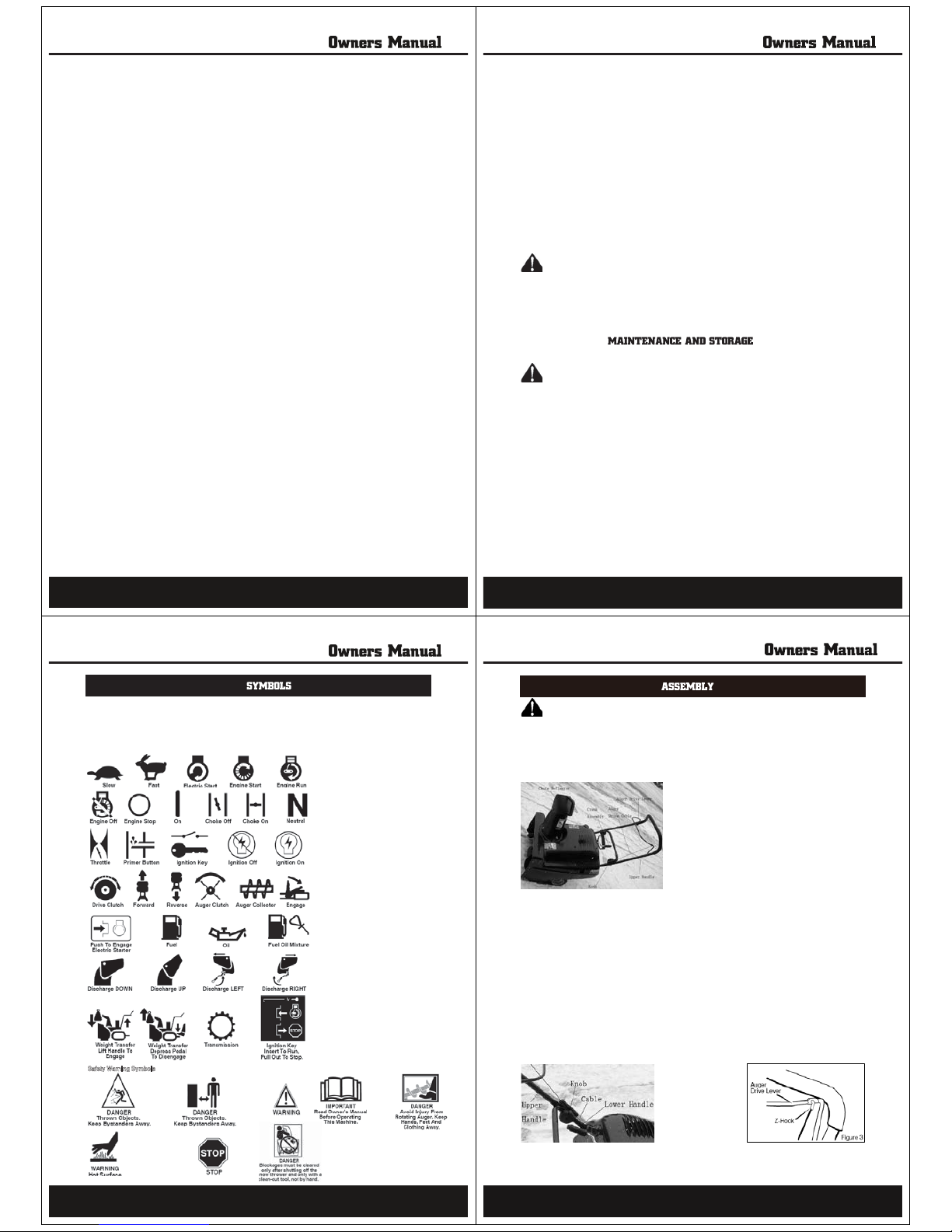
HOW TO CLEAR A CLOGGED DISCHARGE CHUTE
WARNING: Hand contact with the rotating impeller inside the discharge chute is
the most common cause of injury associated with snow throwers. Never use your hand to clean out the
discharge chute.
To Clear The Chute:
1. SHUT OFF THE ENGINE!
2. Wait 10 seconds to be sure that the impeller blades have stopped rotating.
3. Always use a clean-out tool, not your hands.
Use a clean-out tool to remove snow from the auger housing.
1. Release the auger drive lever.
2. Pull out the key.
3. Disconnect spark plug wire.
4. Do not place your hands in the auger or discharge chute. Use a clean-out tool to remove snow or debris.
WARNING: Blockage must be cleared only after shutting off the snow thrower and only with a
clean-out tool, not by hand.
14
SNOW THROWING TIPS
1. When the handle is raised, the auger blades will engage the ground and the snow thrower will move forward.
When the auger drive lever is released, the auger blades will stop.
2. Most efficient snow throwing is accomplished when the snow is removed immediately after if falls.
3. Let the engine (motor) and the snow thrower adjust to outdoor temperature before starting to clear snow.
4. For complete snow removal, slightly overlap each previous path.
5. Whenever possible, discharge the snow down wind.
6. The distance the snow will be discharged can be adjusted by moving the discharge chute deflector. Raise
the deflector for more distance or lower the deflector for less distance.
7. In windy conditions, lower the chute deflector to direct the discharged snow close to the ground where it is
less likely to blow into unwanted areas.
8. For safety and to prevent damage to the snow thrower, keep the area to be cleared free of stones, toys and
other foreign objects.
9. When clearing snow from crushed rock or gravel driveways, do not allow the auger blades to contact the
driveway. Move the handle down to slightly raise the auger blades.
10. The forward speed of the snow thrower is dependent on the depth and weight of the snow. Experience will
establish the most effective method of using the snow thrower under different conditions.
11. After each snow throwing job, allow the engine to run for a few minutes. The snow and accumulated ice will
melt off the engine.
12. Clean the snow thrower after each use.
13. Remove ice, snow and debris from the entire snow thrower. Flush with water to remove all salt or other
chemicals. Wipe snow thrower dry.
DRY AND AVERAGE SNOW
1. Snow up to eight inches deep can be removed rapidly and easily by walking at a moderate rate. For snow or
drifts of a greater depth, slow your pace to allow the discharge chute to dispose of the snow as rapidly as the
auger receives the snow.
2. Plan to have the snow discharged in the direction the wind is blowing.
WET PACKED SNOW
Move slowly into wet, packed snow. If the wet, packed snow causes the auger to slow down or the discharge
chute begins to clog, back off and begin a series of short back and forth jabs into the snow. These short back
and forth jabs, four to six inches, will “belch” the snow from the chute.
SNOW BANKS AND DRIFTS
In snow of greater depth than the unit, use the same “jabbing” technique described above. Turn the discharge
chute away from the snow bank. More time will be required to remove snow of this type than level snow.
15

CUSTOMER RESPONSIBILITIES
GENERAL RECOMMENDATIONS
The warranty on this snow thrower does not cover items that have been subjected to operator abuse or
negligence. To receive full value from the warranty, the operator must maintain the snow thrower as instructed
in this manual.
EMISSIONS CONTROL
Maintenance, replacement, or repair of the emission control devices and systems can be performed by any
non-road engine repair establishment or individual. However to obtain a “no--charge” emissions control service,
the work must be done by a factory authorized dealer. See the Emissions Warranty.
WARNING: Do not strike the flywheel with a hammer or a hard object. If done, the flywheel can
shatter during operation. Do not tamper with the governor spring, links or other parts to increase
engine speed.
AFTER EACH USE
Run the machine to clear the auger of snow.
To prevent freezing of the auger or controls, remove all
snow and slush from the snow thrower.
Check for any loose or damaged parts.
Tighten any loose fasteners.
Check and maintain the auger.
Check controls to make sure they are functioning properly.
If any parts are worn or damaged, replace immediately.
LUBRICATION BEFORE STORAGE
16
ENGINE SPECIFICATIONS
DISPLACEMENT 196 cc
ROTATE SPEED 4000RPM
BORE 68mm
STROKE 45mm
GASOLINE (CAPACITY) 1.5L
OIL CAPACITY 0.6L(5W30)
SPARKPLUG F7RTC
VALVE CLEARANCE Intake: 0.1~0.15 mm
Exhaust: 0.15~0.2 mm
NOISE(İ7m) 65dbA
DIMENSION(LXWXH) 312×362×335
DRY WEIGHT 15kg
SNOW THROWER ENGINE LUBRICATION
Check the crankcase oil level before starting the engine and after each eight (8) hours of continuous use. See
Figure 16. Add S.A.E. 5W30 motor oil as needed. Synthetic 5W30 is acceptable for all temperatures. Tighten
fill cap/dipstick securely each time you check the oil level.
Change the oil every fifty (50) hours or at least once a year if the snow thrower is not used for fifty (50) hours.
TO CHANGE ENGINE OIL
1. Position the snow thrower so that the oil drain plug is at the lowest point on the engine.
2. When the engine is warm, remove the oil drain plug (see Figure 17) and the oil fill cap/dipstick (see
Figure 16). Drain the oil into a suitable container.
3. After draining all the oil, reinstall the oil drain plug securely.
4. Fill the engine crankcase with the recommended motor oil, pouring slowly. DO NOT OVERFILL. See “To
Add Oil” in the Operation Section.
Figure 17
TO ADJUST OR REPLACE THE SPARK PLUG
Check the spark plug every 25 hours. Replace the spark plug if the electrodes are pitted or burned, if the
porcelain is cracked, or every 100 hours of use. The spark plug is housed in the engine compartment under the
top cover and cannot be seen under normal conditions.
17
1. Open the spark plug access door on the control panel (Figure 18).
2. The spark plug and wire are now visible.
3. Remove the spark plug wire.
4. Clean the area around the spark plug base to prevent dirt from entering the engine when the spark plug is
removed.
5. Remove the spark plug.
6. Check the spark plug. If the spark plug is cracked, fouled or dirty, it must be replaced .
7. Set the gap between the electrodes of the new spark plug at 0.030 inch (Figure 19).
8. Install the spark plug in the cylinder head and firmly tighten.
Figure 18
WARNING: To prevent accidental starting when making any adjustments or repairs, always
disconnect the spark plug wire and place it where it cannot make contact with the spark plug .
ADJUSTAUGERCONTROLCABLE
The auger control cable is adjusted at the factory. During normal use, the auger control cable can become
stretched and the auger drive lever will not properly engage or disengage the auger.
1. Remove the “Z” hook from the auger drive lever (Figure 20).
2. Slide the cable boot, if equipped, up the auger control cable until the cable boot does not cover any
portion of the cable adjustment bracket (Figure 21).
3. Pull the auger control cable through the eyehole in the cable adjustment bracket as shown by the arrow
in Figure 21. This will create enough slack to allow the “Z” hook to be easily removed.
4. Install the “Z” hook into the next available adjustment hole in the cable adjustment bracket. This is the
adjustment hole located one notch down from where the “Z” hook was previously attached.
5. Pull the auger control cable back through the eyehole of the cable adjustment bracket until all the slack is
taken out of the auger control cable.
6. Slide the cable boot back down over the cable adjustment bracket.
7. Install the “Z” hook to the auger drive lever (Figure 20).
8. To check the adjustment, start the snow thrower. Make sure the auger does not rotate when the auger drive
lever is released. Engage the auger drive lever and make sure auger rotates. If the auger does not rotate,
repeat this “Adjust Auger Control Cable” procedure.
18
6725$*(
WARNING: Never store your snow thrower with gasoline in the fuel tank indoors or in an
enclosed, poorly ventilated area. If gasoline remains in the tank, fumes may reach an open flame, spark
or pilot light from a furnace, water heater, clothes dryer, cigarette, etc.
To prevent damage (if snow thrower is not used for more than 30 days) follow the steps below.
SNOW THROWER
1. Thoroughly clean the snow thrower.
2. Lubricate all lubrication points. See the Maintenance section.
3. Be sure that all nuts, bolts and screws are securely fastened. Inspect all visible moving parts for damage,
breakage and wear. Replace if necessary.
4. Touch up all rusted or chipped paint surfaces; sand lightly before painting.
5. Cover the bare metal parts of the blower housing auger and the impeller with rust preventative, such as a
spray lubricant.
NOTE: A yearly checkup or tune-up by a Sears service center is a good way of ensuring that your snow
thrower will provide maximum performance for the next season.
ENGINE
Gasoline must be removed or treated to prevent gum deposits from forming in the fuel tank, filter, hose, and
carburetor during storage. Also, during storage alcohol blended gasoline that uses ethanol or methanol
(sometimes called gasohol) attracts water. It acts on the gasoline to form acids which damage the engine.
1. Run the engine until the fuel tank is empty and the engine stops.
2. If you do not remove the gasoline, use fuel stabilizer supplied with unit or purchase Craftsman Fuel Stabilizer
No. 3550. Add fuel stabilizer to any gasoline left in the tank to minimize gum deposits and acids. If the fuel tank
is almost empty, mix stabilizer with fresh gasoline in a separate container and add some to the fuel tank.
3. Always follow the instructions on the stabilizer container. After the stabilizer is added to the fuel tank, run the
engine at least ten minutes to allow the mixture to reach the carburetor.
4. Change the engine oil.
5. Remove the spark plug and pour about 15 ml (1/2 oz) of engine oil into the cylinder. Replace the spark plug
and crank slowly to distribute the oil.
6. Store in a clean and dry area, but NOT near a stove, furnace or water heater which uses a pilot light or any
device that can create a spark.
OTHER
1. If possible, store your snow thrower indoors and cover it to give protection from dust and dirt.
2. If the snow thrower must be stored outdoors, put the snow thrower on blocks to raise it off of the ground.
3. Cover the snow thrower with a suitable protective cover that does not retain moisture. Do not use plastic.
IMPORTANT: Never cover snow thrower while engine and exhaust areas are still warm.
19

20
APA Part No. Part No. Description
SB055E-A-01-WR ---- ENGINE (9A4130203E1)
SB055P-A-04-WR 67403-036001 TANK, FUEL 2.0QT
SB055P-A-05-WR 67403-000339 RING, FOAM FUEL TANK
SB055P-A-06-WR 67403-000340 CAP, FUEL
SB055P-A-07-WR 67402-000178-C WASHER, FLAT
SB055P-A-08-WR 67402-000158-C SCREW, 1/4-20 X 0.75
SB055P-A-09-WR 67403-036005-001 BRACKET, FUEL TANK
SB055P-A-10-WR 67402-000105-C NUT, 1/4-20 HEX
SB055P-A-11-WR 67403-000313-C SCREW, 1/4-20 X 2.00
SB055P-A-12-WR 67402-000105-C NUT, 1/4-20 HEX
SB055P-A-13-WR 67402-000216-C NUT, 5/16-18 HEX CONTROL LOCK
SB055P-A-15-WR 67403-037000-001 CRADLE, WELDMENT
SB055P-A-16-WR 67403-000315-C BOLT, 5/16-18 X 0.865
SB055P-A-17-WR 67403-000318-C BOLT, ENGINE MOUNT
SB055P-A-18-WR 67403-036002 HOSE, FUEL 12 INCHES (CUT TO 6 INCH LENGTH)
SB055P-A-19-WR 67403-036004 CLAMP, FUEL LINE
21
A
SB055P-A-20-WR 67403-036100 FILTER-FUEL
SB055P-A-21-WR ………… HOSE, FUEL 12 INCHES (CUT TO 8 INCH LENGTH)
SB055P-A-22-WR 67403-036003 CLAMP, HOSE SCREW
SB055P-A-23-WR 67403-000312 PLATE, BOLTING SUPPORT
SB055P-A-24-WR 67403-000310-001 FRAME, RIGHT HAND
SB055P-A-25-WR 67403-000311 CHANNEL, FRAME SUPPORT
SB055P-A-26-WR 67403-000309 FRAME, LEFT HAND
SB055P-A-27-WR 67403-038001 LF ARM, IDLER BRACKET
SB055P-A-28-WR 67403-000308-B BRAKE PAD
SB055P-A-29-WR 67403-000321 ROD, CLUTCH LINKAGE
SB055P-A-30-WR 67401-000039-C NUT, 3/8-16 JAM CONTROL LOCK
SB055P-A-31-WR 67403-038005 WIRE, BRAKE
SB055P-A-32-WR 67403-038002 PULLEY, IDLER
SB055P-A-33-WR 67403-038006 ROLLER, PINCH
SB055P-A-34-WR 67403-038003-C SCREW, 3/8-16 X 1.62
SB055P-A-35-WR 67403-000324-W SPRING, EXTENSION .38 OD X .039 X 2.50
SB055P-A-36-WR 67403-000325-W SPRING, EXTENSION .75 OD X .069 X 2.00
SB055P-A-37-WR 67403-000338 BELT
SB055P-A-38-WR 67403-000306-B ARM, IDLER PIVOT
SB055P-A-39-WR 67403-000307-C BOLT SHD .500 X .177 X .31
SB055P-A-40-WR 67403-038004-C WASHER, FLAT
SB055P-A-41-WR 67403-000335 PULLEY, ENGINE
SB055P-A-42-WR 67403-000323-C PIN, COTTER
SB055P-A-43-WR 67403-000322-C WASHER, FLAT #8
SB055P-A-44-WR 67403-000316-F GUIDE, BELT
SB055P-A-45-WR 67402-000105-C NUT, 1/4-20
SB055P-A-46-WR 67401-000073-C WASHER
SB055P-A-47-WR 67403-000317-C SCREW
SB055P-A-48-WR 67402-000182-C SCREW,
SB055P-A-49-WR 67403-000307-C SCREW,
SB055P-A-50-WR 67403-000337-F SPACER, DRIVE PULLEY
SB055P-A-51-WR 67403-000336 BOLT, ENGINE PULLY
SB055P-A-52-WR 67403-000318-C BOLT,
SB055P-A-53-WR 67403-000317-C SCREW .
SB055P-A-54-WR ……….. TIE, CABLE
22
APA Part No. Part No. Description
B
SB055P-B-01-WR 67403-000332-C Screw 1/4--20 x 1.00
SB055P-B-02-WR 67402-000105-C Nut, Hex 1/4--20
SB055P-B-03-WR 67402-000158-C Screw, 1/4--20 x .75
SB055P-B-04-WR 67402-000178-C Washer, Flat
SB055P-B-05-WR 67403-001011 Housing Assy, Auger
SB055P-B-06-WR 67402-000182-C Screw, 1/4--20 x .63
SB055P-B-07-WR 67403-002000 Auger Assembly, 21”
SB055P-B-08-WR 67403-035001 Retainer, Bearing
SB055P-B-09-WR 276-6203-2ZBearing
SB055P-B-10-WR 67403-000333 Sleeve, Spacer
SB055P-B-11-WR 67403-000330-B Bearing Retainer
SB055P-B-12-WR 67403-000334 Pulley, Auger Drive V6
SB055P-B-13-WR 67403-000331 Bearing, Flange
23

SB055P-C-01-WR 67403-000354-001 Handle &Grip Assembly
SB055P-C-02-WR 67403-000355-001 Control, Bail
SB055P-C-03-WR 67401-000086 Boot, Clutch Spring
SB055P-C-04-WR 67403-021100 Cable, Upper Control
SB055P-C-05-WR 67402-000167-B Bracket, Control Adjust
SB055P-C-06-WR 67403-041000 Cable, Lower Control
SB055P-C-07-WR 67403-000325-W Spring
SB055P-C-08-WR 67403-000356-C U--Bolt
SB055P-C-09-WR 67403-000357-C Washer
SB055P-C-10-WR 67403-042000 Knob
SB055P-C-11-WR 67403-000304-001 Handle, Lower
SB055P-C-12-WR 67402-000105-C Nut
SB055P-C-13-WR 67402-000178-C Washer
SB055P-C-14-WR 67403-000314-C Screw, 1/4--20 x1.25
24
APA Part No. Part No. Description
C
SB055P-D-01-WR 67403-000327-C Screw 1/4--14
SB055P-D-02-WR 67403-000329 Retainer, Chute Ring
SB055P-D-03-WR 67403-000328 Ring, Chute
SB055P-D-04-WR 67401-000002-C Bolt, Carr 5/16--18x.75
SB055P-D-06-WR 67403-001004 Neck, Chute
SB055P-D-07-WR 67403-000190 Chute, 21” Upper
SB055P-D-08-WR 67401-000019 T--Knob
SB055P-D-09-WR 67401-000073-C Washer
SB055P-D-10-WR 67403-000351-W Lockwasher
SB055P-D-11-WR 67402-000216-C Locknut 5/16--18
SB055P-D-12-WR 67401-000017-C Bolt, Carr 5/16--18
25
APA Part No. Part No. Description
D
SB055P-D-13-WR 67403-000352-C Bolt, Upper Chute
SB055P-D-14-WR 67402-000130-C Washer
SB055P-D-15-WR 67402-000127-C Nut
SB055P-D-16-WR 67403-000191-001 Chute, Lower
SB055P-D-18-WR 67402-000115 Gear, 9--Tooth
SB055P-D-19-WR 67403-000327-C Screw, 1/4--14 x .75
SB055P-D-20-WR 67403-034002 Nut, Push
SB055P-D-21-WR 67403-034001 Knob, Sleeve
SB055P-D-22-WR 67402-000130-C Washer
SB055P-D-23-WR 67403-034003 Crank, Chute
SB055P-D-25-WR 67402-000116-C Pin, Hair
SB055P-D-26-WR 67402-024000-C Yoke Assy, Adapter
SB055P-D-27-WR 67401-000122-C Pin, Cotter
SB055P-D-28-WR 67402-000119-C Pin, Universal Joint
SB055P-D-29-WR 67402-000121-C Pin, Clevis
SB055P-D-30-WR 67402-000120 Block, Universal
SB055P-D-31-WR 67403-023000-C Rod, Lower Crank
SB055P-D-32-WR 67402-000158-C Screw 1/4--20 x .75
SB055P-D-33-WR 67403-001012 Blade, Scraper
SB055P-D-34-WR 67402-000109-C Locknut, Hex 1/4--20
26
APA Part No. Part No. Description
SB055P-E-01-WR 67403-019001 Panel, Control
SB055P-E-02-WR 67403-000320-C Screw 1/4--20 x 1.37
SB055P-E-03-WR 67402-000178-C Washer
SB055P-E-04-WR 67402-000105-C Nut, 1/4--20
SB055P-E-05-WR ---------------- Bushing, Chute Crank
SB055P-E-06-WR ---------------- Nut, 5/8--32
SB055P-E-07-WR --------------- Keys &Ring, Starter
SB055P-E-08-WR 67403-000359 Bulb, Fuel Primer
SB055P-E-09-WR 67403-000358 Panel, Cover Access
SB055P-E-10-WR -------------- Nut, Keps 1/4--20
SB055P-E-11-WR -------------- Hose, Primer 9.5”
SB055P-E-12-WR ------------- Switch, Ignition
SB055P-E-13-WR 67403-000304-001 Handle, Lower
SB055P-E-14-WR 67403-000327-C Screw 1/4--14 x .75
SB055P-E-15-WR 67403-000343-W J--Nut 1/4--10
SB055P-E-16-WR 67403-000346 Cover, Bottom
27
APA Part No. Part No. Description
E

SB055P-E-17-WR 67403-000341 Cover, Belt
SB055P-E-18-WR 67403-000344-C Screw 10--24 x .5
SB055P-E-19-WR 67403-000345-C Locknut, Hex 10--24
SB055P-E-20-WR 67402-000109-C Locknut, Hex 1/4--20
SB055P-E-21-WR 67402-000182-C Screw 1/4--20 x .63
SB055P-E-22-WR 67403-000347 Cover, Top
SB055P-E-23-WR ------------- Knob, Standard Recoil
SB055P-E-24-WR ------------- Washer
SB055P-E-25-WR 67403-000350 Cover, Oil Access
SB055P-E-26-WR 67403-000348 Gasket, Chute Ring
SB055P-E-27-WR 67403-000349-C Nut, Push
SB055P-E-28-WR ------------ Clamp, Cable
SB055P-F-01-WR 67403-000303-D Retainer, E—Ring
SB055P-F-02-WR 67403-000302-C Washer
SB055P-F-03-WR 67403-039000 Wheel and Tire 7” x 1.50”
SB055P-F-05-WR 67403-000301-C Rod, Axle
SB055P-F-06-WR 67403-000302-C Washer
28
APA Part No. Part No. Description
F
SB055P-G-1-WR 910311-001 Decal, Run and Choke
SB055P-G-2-WR 910312-001 Decal, Primer Assemble
SB055P-G-3-WR 910314-001 Decal, Auger Control
SB055P-G-4-WR 910310-001 Decal, Spark Plug Access
SB055P-G-5-WR 910313-001 Decal, Auger Danger
SB055P-G-6-WR 910318-001 Decal, Danger Chute Hand
SB055P-G-7-WR 910316-001 Decal, Danger Muffler
SB055P-G-8-WR 910317-001 Decal, Auger Danger
29
APA Part No. Part No. Description
G
Steele® warrants to the original purchaser who uses the product in a consumer application (personal,
residential or household usage) that all products covered under this warranty are free from defects
in material and workmanship for two years from the date of purchase. All products covered by this
limited warranty which are used in commercial applications (i.e. income producing) are warranted
to be free of defects in material and workmanship for 90 days from the date of original purchase.
Products covered under this warranty include air compressors, tools, service parts, pressure washers
snow blower and generators.
Steele® will repair or replace, at Steele®’s sole option, products or components which have failed
within the warranty period. Service will be scheduled according to the normal work flow and business
hours at the service center location, and the availability of replacement parts. All decisions of Steele®
with regard to this limited warranty shall be final.
This warranty gives you specific legal rights, and you may also have other rights which vary from
state to state.
RESPONSIBILITY OF ORIGINAL PURCHASER (initial User):
To process a warranty claim on this product, DO NOT return item to the retailer. The product must
be evaluated by an Authorized Warranty Service Center. For the location of the nearest Authorized
Warranty Service Center contact the retailer or place of purchase.
Retain original cash register sales receipt as proof of purchase for warranty to work.
Use reasonable care in the operation and maintenance of the product as described in the Owner’s
Manual(s).
Deliver or ship the product to the Authorized Warranty Service Center. Freight costs, if any must be
paid by the purchaser. If the purchaser does not receive satisfactory results form the Authorized
Warranty Service Center, the purchaser should contact Steele® toll free 888-896-6881.
THIS WARRANTY DOES NOT COVER:
Merchandise sold as reconditioned, used as rental equipment, or floor or display models.
Merchandise that has become damaged or inoperative because of ordinary wear, misuse, cold, heat,
rain, excessive humidity, freeze damage, use of improper chemicals, negligence, accident, failure to
operate the product in accordance with the instructions provided in the Owner’s Manual(s) supplied
with the product, improper maintenance, the use of accessories or attachments not recommended
by Steele®, or unauthorized repair or alterations.
/AL=EN=J@PN=JOLKNP=PEKJ?KOPOKBIAN?D=J@EOA@APANIEJAJKP to be defective.
osts associated with assembly, required oil, adjustments or other installation and start-up costs.
Expendable parts or accessories supplied with the product which are expected to become inoperative
or unusable after a reasonable period of use.
30
31
Merchandise sold by Steele® which has been manufactured by and identified as the product of another
company, such as gasoline engines. The product manufacturer’s warranty, if any, will apply.
ANY INCIDENTAL, INDIRECT OR CONSEQUENTIAL LOSS, DAMAGE, OR EXPENSE THAT MAY RESULT
FROM ANY DEFECTS, FAILURE OR MALFUNCTION OF THE PRODUCT IS NOT COVERED BY THIS
WARRANTY. Some states do not allow the exclusion, so it may not apply to you.
IMPLIED WARRANTIES, INCLUDING THOSE OF MERCHANTABILITY OR FITNESS FOR A PARTICULAR
PURPOSE, ARE LIMITED TO TWO YEARS FROM THE DATE OF ORIGINAL PURCHASE. Some states do
not allow limitations on how long an implied warranty lasts, so the above limitations may not apply
to you.
Distributed by:
STEELE PRODUCTS
all rights reserved
Table of contents
Other STEELE PRODUCTS Snow Blower manuals