SteelMax BM-7 User manual
The tools of innovation.
15335 E. Fremont Drive, Centennial, CO 80112
1–87STEELMAX, FAX 303–690–9172
www.steelmax.com [email protected]
OPERATOR’S MANUAL
B
BM
M-
-7
7
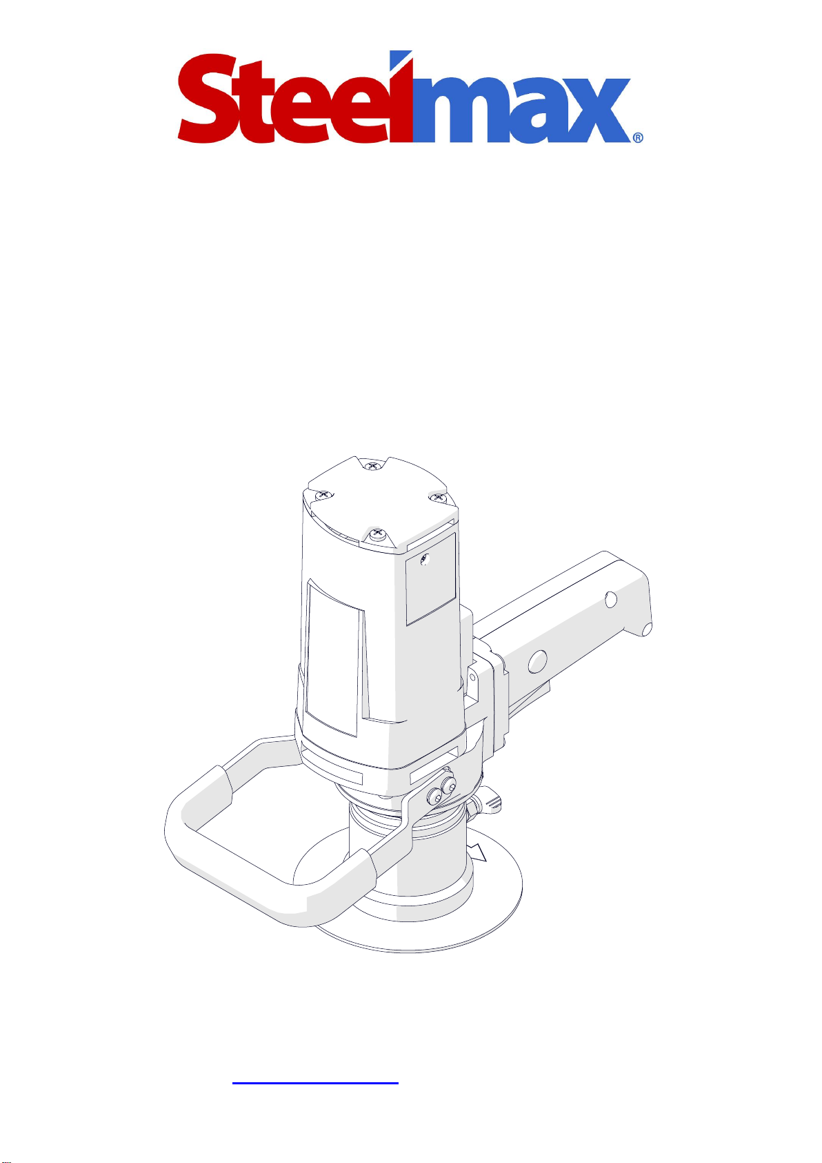
BEVELING MACHINE

Contents
1. GENERAL INFORMATION............................................................................................... 3
1.1. Application................................................................................................................. 3
1.2. Technical data............................................................................................................ 3
1.3. Equipment included ................................................................................................... 4
1.4. Dimensions................................................................................................................ 5
1.5. Design ....................................................................................................................... 6
2. SAFETY PRECAUTIONS.................................................................................................. 7
3. STARTUP AND OPERATION........................................................................................... 9
3.1. Installing and removing the cutting inserts.................................................................. 9
3.2. Installing and removing the milling head ...................................................................10
3.3. Adjusting the bevel width ..........................................................................................12
3.4. Adjusting the guide for beveling with radius ..............................................................12
3.5. Operating..................................................................................................................13
3.6. Replacing the brushes ..............................................................................................14
4. ACCESSORIES...............................................................................................................15
4.1. Radius insert positioner.............................................................................................15
4.2. Anti-scratch guide sticker..........................................................................................16
4.3. Milling tools...............................................................................................................16
5. SPARE AND WEARING PARTS......................................................................................17
6. WIRING DIAGRAM..........................................................................................................18
7. DECLARATION OF CONFORMITY.................................................................................19
8. EXPLODED DRAWINGS AND PARTS LIST....................................................................20
9. WARRANTY CARD..........................................................................................................24
BM-7
BM-7 Operator’s Manual
3
1. GENERAL INFORMATION
1.1. Application
The BM-7 is a beveling machine designed to bevel plates and pipes made of steel or
aluminum alloys.
Depending on the milling head, the machine allows you to bevel at the angle of 30°
or 45°. The minimum workpieces thickness is 1.5 mm (1/16″). The maximum bevel
width is 7mm (9/32″). The included milling head allows you to bevel at the angle of
45°. Radius inserts allow you to bevel with a radius of 2, 3, 4, or 5 mm. The minimum
diameter of a hole to be machined is 35 mm (1-3/8″).
An optional milling heads allow you to machine holes with diameters of at least
22.5 mm (7/8″). A sticker protects aluminum workpieces from scratches.
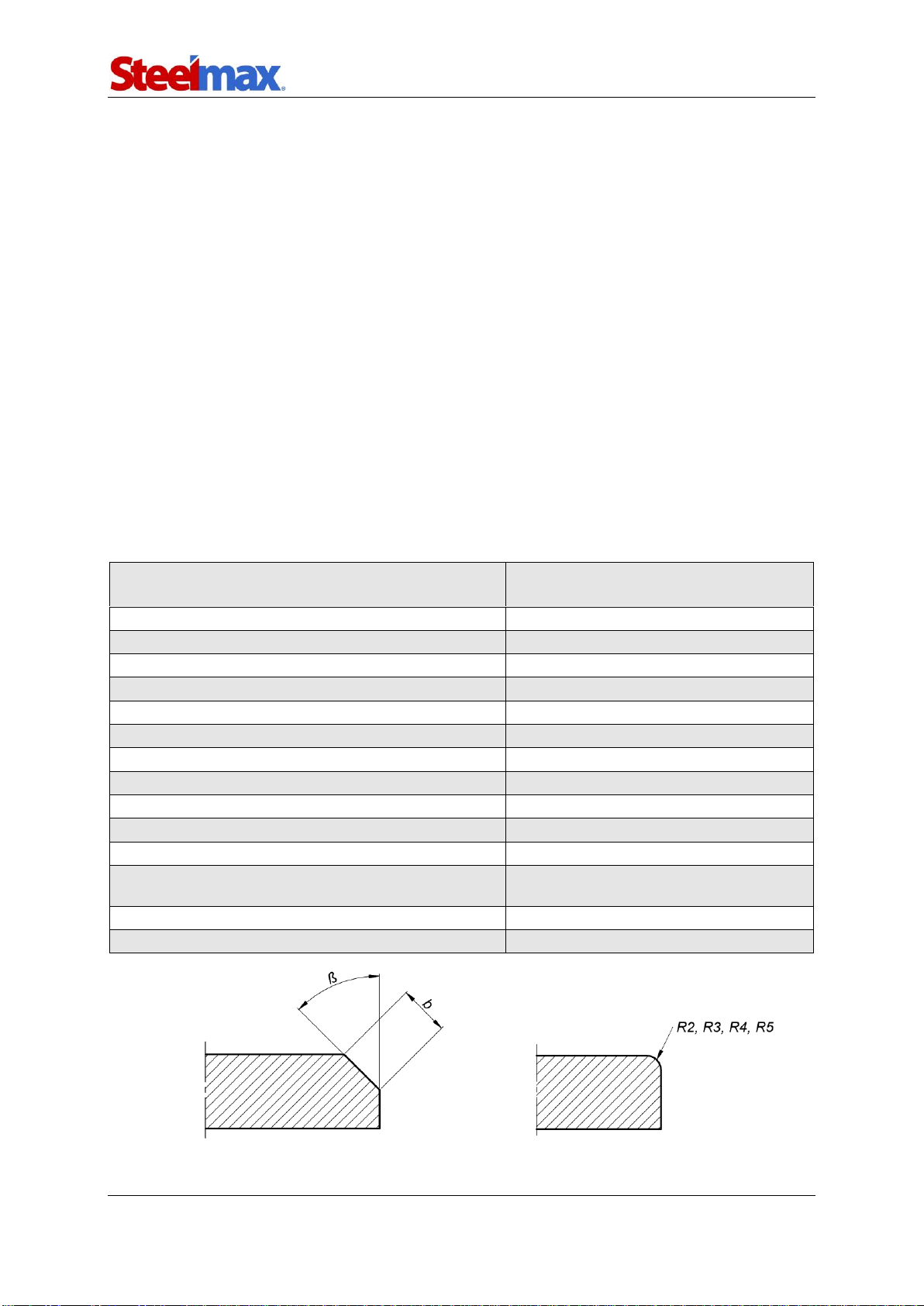
1.2. Technical data
Voltage
1~ 110–120 V, 50–60 Hz
1~ 220–240 V, 50–60 Hz
Power
1080 W
Rotational speed without load
6200 rpm
Rotational speed with load
3200 rpm
Protection level
IP 20
Protection class
I
Maximum bevel width (b)
7 mm (9/32″, Fig. 1)
Bevel angle (ß, depends on the milling head)
30° (option), 45° (Fig. 1)
Minimum workpiece thickness
1.5 mm (1/16″)
Minimum hole diameter
22.5 mm (7/8″, option), 35 mm (1-3/8″)
Edge radius
2 mm, 3 mm, 4 mm, 5 mm (Fig. 1)
Noise level
More than 70 dB
Vibration level
Machine harmful for health.
Take periodic breaks during work.
Required ambient temperature
0–40°C (34–104°F)
Weight
6.1 kg (13 lbs)
Fig. 1. Bevel dimensions
BM-7
BM-7 Operator’s Manual
4
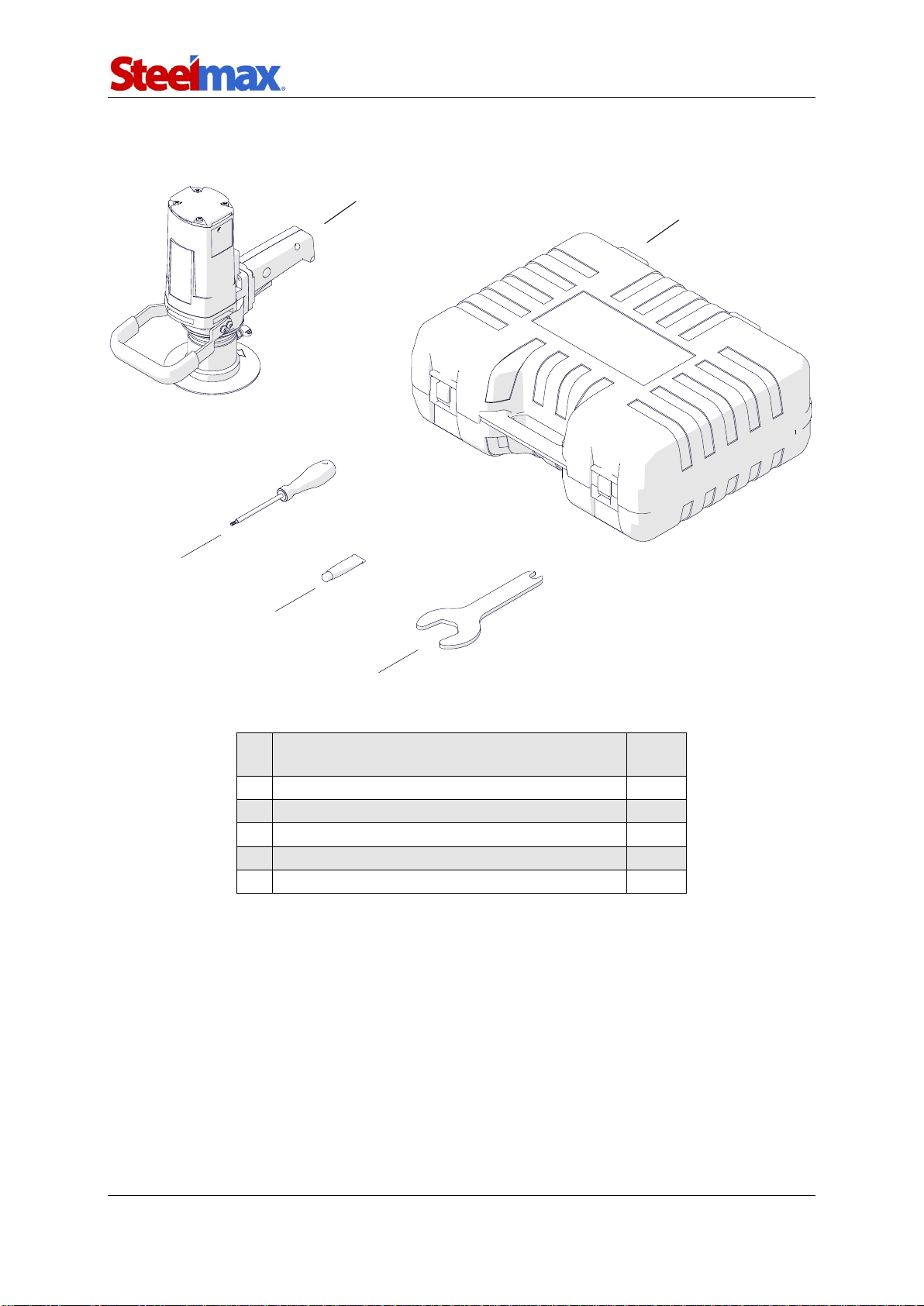
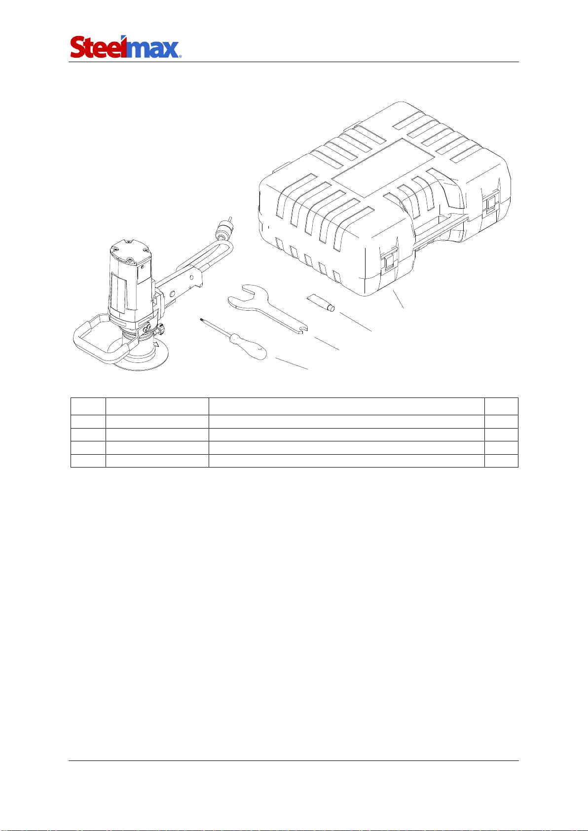
1.3. Equipment included
1
Beveling machine (includes 45° milling head
with Ø35 mm roller, without cutting inserts)
1 unit
2
Plastic box
1 unit
3
Special flat wrench
1 unit
4
Grease for screws 5 g (0.2 oz)
1 unit
5
Torx T15 screwdriver
1 unit
–
Operator’s Manual
1 unit
3
1
2
4
5
BM-7
BM-7 Operator’s Manual
5
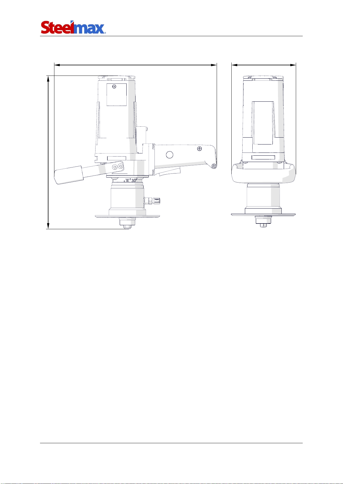
1.4. Dimensions
339 mm (13-11/32″)
319 mm (12-9/16″)
135 mm (5-5/16″)
BM-7
BM-7 Operator’s Manual
6
1.5. Design
45° milling head with Ø35 mm roller
Handle
ON/OFF switch
Clamping screw
Guide
Sleeve
Switch lock

BM-7
BM-7 Operator’s Manual
7
2. SAFETY PRECAUTIONS
1. Before use, read this Operator’s Manual and complete a training in occupational
safety and health.
2. Use only in applications specified in this Operator’s Manual.
3. Make sure that the machine has all parts and they are genuine and not damaged.
4. Make sure that the specifications of the power source are the same as those
specified on the rating plate.
5. Do not carry the machine by the cord and do not pull the cord. This can cause
damage and electric shock.
6. Keep untrained bystanders away from the machine.
7. Before each use, ensure the correct condition of the machine, power source,
power cord, plug, control parts, and tools.
8. Before each use, make sure that no part is cracked or loose. Make sure to
maintain correct conditions that can have an effect on the operation of the
machine.
9. Keep the machine dry. Do not expose the machine to rain, snow, or frost.
10. Keep the work area well lit, clean, and free of obstacles.
11. Do not use near flammable materials, or in explosive environments.
12. Use only tools specified in this Operator’s Manual.
13. Do not use tools that are dull or damaged.
14. Make sure that the cutting inserts and the milling head are correctly attached.
Remove wrenches from the work area before you connect the machine to the
power source.
15. Do not use the machine so that the milling head is up.
16. If the cutting edge of an insert is worn, turn all inserts by 90°. If all cutting edges
are worn, install new inserts specified in this Operator’s Manual.
17. Use eye and ear protection, non-skid footwear, and protective clothing. Do not use
loose clothing.
18. Do not touch chips or moving parts. Do not let anything catch in moving parts.
19. After each use, clean the machine and the milling head with a dry cotton cloth
and no chemical agents. Do not remove chips with bare hands.
20. Maintain the machine and install/remove parts and tools only after you unplug the
machine from the power source.

BM-7
BM-7 Operator’s Manual
8
21. Repair only in a service center appointed by the seller.
22. If the machine falls, is wet, or has any damage, stop the work and immediately
send the machine to the service center for check and repair.
23. If you are not going to use the machine, remove it from the work area and keep it
in a safe and dry place.
24. If you are not going to use the machine for an extended period, put anti-corrosion
material on the steel parts.

BM-7
BM-7 Operator’s Manual
9
3. STARTUP AND OPERATION
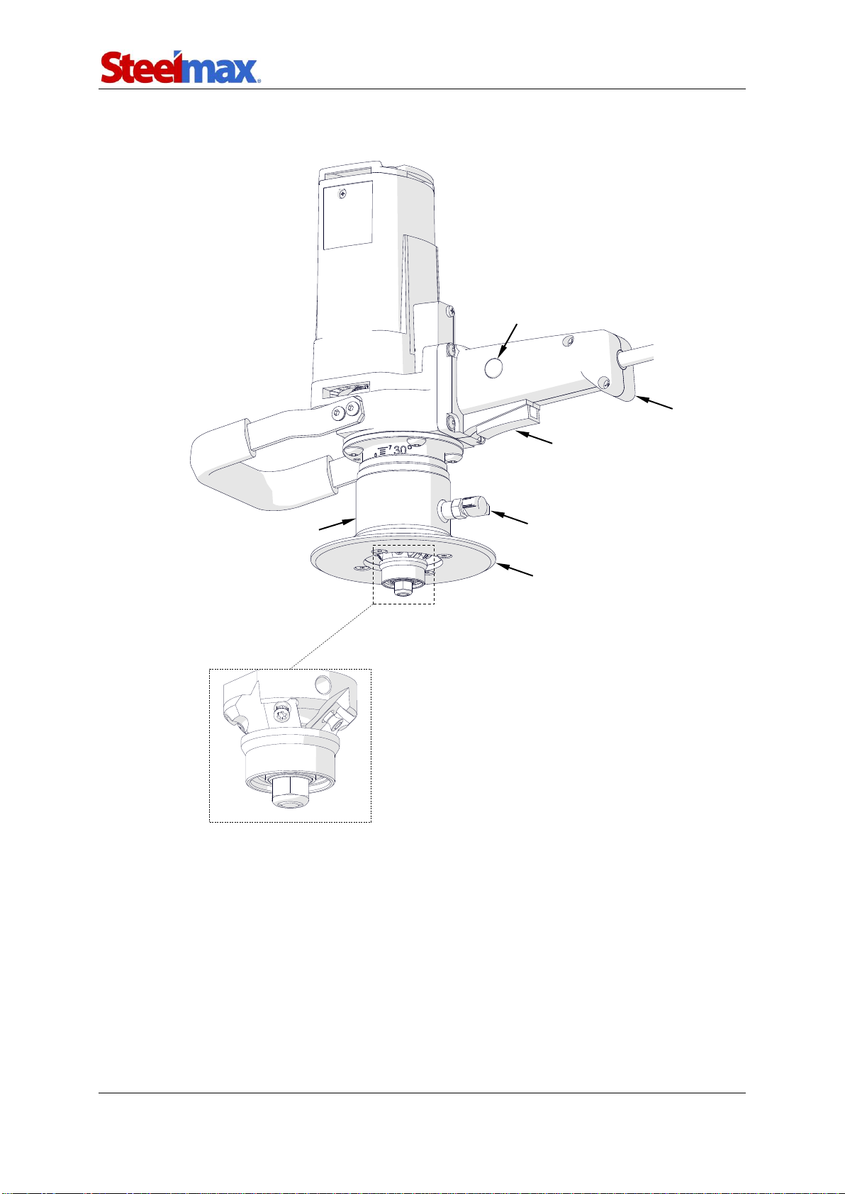
3.1. Installing and removing the cutting inserts
Unplug the power cord. Loosen the screw (1) and then turn the sleeve (2) to lower it
as far as possible and get access to the milling head. Use the special wrench (3) to
loosen the roller, and then use the screwdriver (4) to remove the cutting inserts. Clean
the sockets.
To change the cutting edge, turn the inserts by 90°, push them to the sockets, and
tighten the inserts and the roller. If all cutting edges are worn, install new inserts. Make
sure that the bottom of each insert is in full contact with the socket (5).
Each week clean the threads of the mounting screws for inserts and put the
supplied grease on the threads.
2
1
CORRECT
INCORRECT
5
3
4
BM-7
BM-7 Operator’s Manual
10
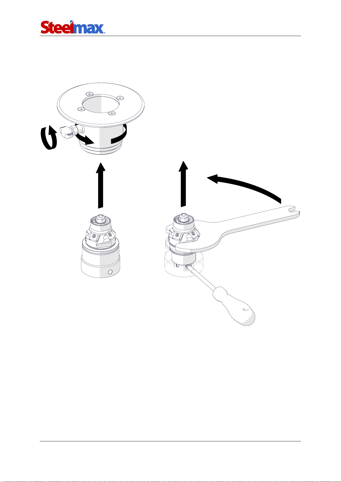
3.2. Installing and removing the milling head
Unplug the power cord. To remove the milling head, continue in the sequence that
follows.
1
2
4
5
3
6
BM-7
BM-7 Operator’s Manual
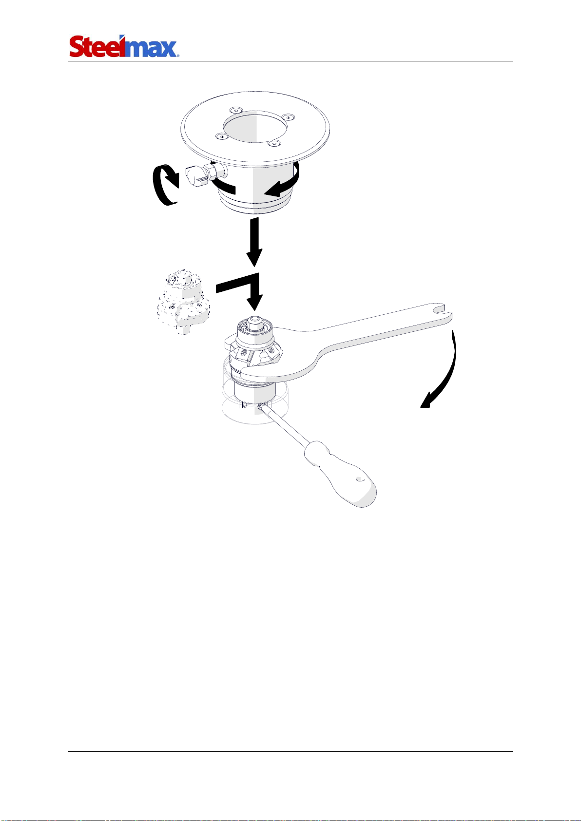
11
To install the milling head, continue in the sequence that follows.
1
2
3
4
5
6
BM-7
BM-7 Operator’s Manual
12
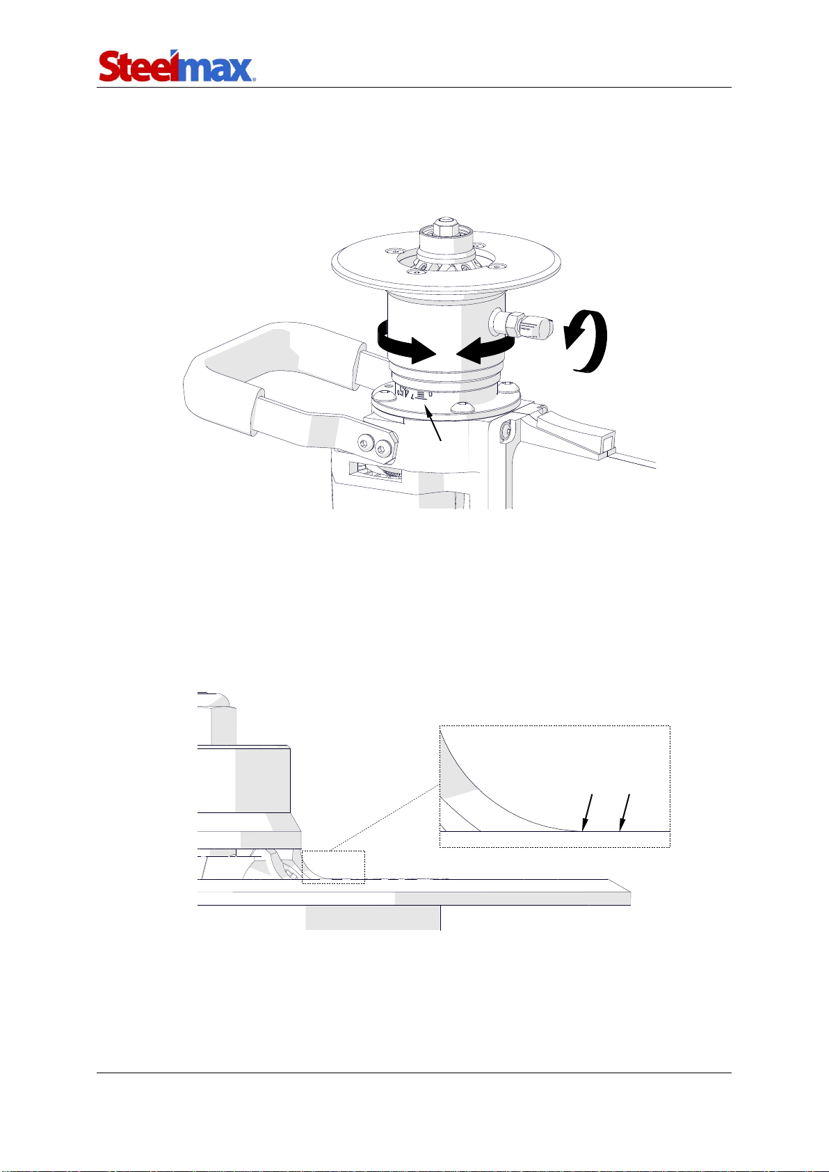
3.3. Adjusting the bevel width
Unplug the power cord. Loosen the clamping screw (1) and turn the sleeve (2) so
that the scale (3) shows the required bevel width. Tighten the screw.
3.4. Adjusting the guide for beveling with radius
Unplug the power cord. Then, loosen the clamping screw and turn the sleeve to set
the surface (1)on the height of the end of the cutting edge (2). You can also use an
optional radius insert positioner to set the guide correctly. Tighten the screw. Bevel a
test edge, and if necessary adjust the position of the guide again.
2
1
1
2
3

BM-7
BM-7 Operator’s Manual
13
3.5. Operating
Install the required milling head with cutting inserts, and set the required bevel width.
Connect the machine to the power source and put the machine on the left as in the
figure. Make sure that the workpiece is stable.
To start the motor, press and hold the switch lock (1) and the ON/OFF switch (2),
and then release the lock (1). Next, wait some seconds until the speed is at the
maximum. Press the machine to the workpiece with the two hands. Then, slowly slide
the machine toward the edge until the tool starts cutting. Move the machine from left
to right (4).
Bevel in two passes. Set the bevel width to a value that will allow the feed of
1 m/min without using too much force.
If there is vibration in the machine or if the cutting inserts are dull or damaged,
turn off the machine. Then, turn the cutting inserts by 90° to change the cutting edges.
If all cutting edges are worn, install new inserts.
Replace inserts before they become dull to prevent the overloading. Also, take
periodic breaks during work. This prevents overheating and damage to the windings.
After the work is finished, release the ON/OFF switch to turn off the motor. Then,
wait until the rotation stops, and unplug the power cord.
Clean the machine with a dry cotton cloth and no chemical agents.
4
1
3
2
BM-7
BM-7 Operator’s Manual
14
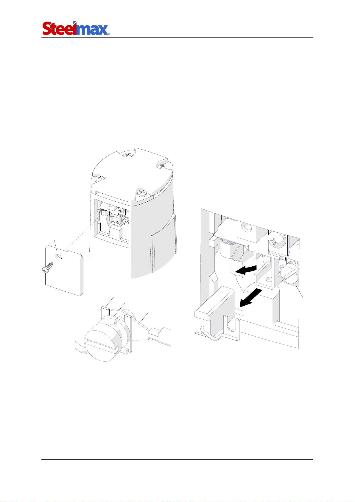
3.6. Replacing the brushes
Check the condition of the carbon brushes every 100 work hours. To do this, unplug
the power cord, and remove the cover (1). Next, loosen the screw (2), pry off the
spring (3), and remove the brush (4). If the length of the brush is less than 5 mm
(0.2″), replace the two brushes with new ones.
To install, continue in reverse order. Make sure to put the terminal of the brush
wire (5) between the washer (6) and the terminal of the motor wire (7). Then, let the
motor operate with no load for 20 minutes.
1
2
3
4
7
6
5

BM-7
BM-7 Operator’s Manual
15
Part number:
UST-0509-16-00-00-0
R2
R3
R4
R5
4. ACCESSORIES
4.1. Radius insert positioner
Allows the guide to be set correctly for beveling with a radius of 2, 3, 4, or 5 mm.
Unplug the power cord. Then, lower the sleeve to get access to the cutting inserts.
Next, put the positioner from the top (1) so that the edge marked with a given radius is
aligned with the edges of three cutting inserts with the same radius (2). Turn the
sleeve (3) until the guide is in contact with the positioner (4).
2
4
1
3

BM-7
BM-7 Operator’s Manual
16
4.2. Anti-scratch guide sticker
Self-adhesive guide sticker protects aluminum workpieces from scratches. After you
remove the sticker, clean the guide with petroleum ether.
4.3. Milling tools
Part number
Part name
GLW-0540-09-00-00-0
30° milling head (includes: Ø35 mm roller, mounting screws for inserts;
4 cutting inserts required)
PLY-000391
Cutting insert for steel (sold per 10 in a set);
for GLW-0540-08-00-00-0 and GLW-0540-09-00-00-0
PLY-000423
Cutting insert for aluminum (sold per 10 in a set);
for GLW-0540-08-00-00-0 and GLW-0540-09-00-00-0
PLY-000360
R2 cutting insert (sold per 10 in a set); only for GLW-0540-08-00-00-0
PLY-000159
R3 cutting insert (sold per 10 in a set); only for GLW-0540-08-00-00-0
PLY-000160
R4 cutting insert (sold per 10 in a set); only for GLW-0540-08-00-00-0
PLY-000161
R5 cutting insert (sold per 10 in a set); only for GLW-0540-08-00-00-0
GLW-0540-16-00-00-0
45° milling head (includes: Ø22.5 mm roller, mounting screws for inserts;
3 cutting inserts required)
PLY-000282
Cutting insert (sold per 10 in a set) for GLW-0540-16-00-00-0
Part number:
NKL-0540-15-00-00-0

BM-7
BM-7 Operator’s Manual
17
5. SPARE AND WEARING PARTS
Part number
Part name
GLW-0540-08-00-00-0
45° milling head (includes: Ø35 mm roller, mounting screws for inserts;
4 cutting inserts required)
RLK-0540-08-02-00-0
Ø35 mm roller for GLW-0540-08-00-00-0 and GLW-0540-09-00-00-0
RLK-0540-16-02-00-0
Ø22.5 mm roller for GLW-0540-16-00-00-0
SRB-000289
Mounting screw for insert
for GLW-0540-08-00-00-0 and GLW-0540-09-00-00-0
SRB-000311
Mounting screw for insert for GLW-0540-16-00-00-0
WKT-000005
T15P screwdriver for mounting screws
SMR-000005
Grease for mounting screws (5 g, 0.17 oz)
SCZ-000009
Carbon brush 115 V / 230 V

BM-7
BM-7 Operator’s Manual
18
6. WIRING DIAGRAM

BM-7
BM-7 Operator’s Manual
19
7. DECLARATION OF CONFORMITY
Declaration of Conformity
PROMOTECH sp. z o.o.
ul. Elewatorska 23/1
15-620 Białystok
Poland
We declare with full responsibility that:
BM-7 Beveling Machine
is manufactured in accordance with the following standards:
•EN 60745-1
•EN 55014
•EN ISO 12100
and satisfies regulations of the guidelines: 2014/30/EC, 2014/35/EC, 2006/42/EC.
Person authorized to compile the technical file:
Marek Siergiej, ul. Elewatorska 23/1, 15-620 Białystok, Poland
Białystok, 17 October 2018 ___________________________
Marek Siergiej
CEO
BM-7
BM-7 Operator’s Manual
20
8. EXPLODED DRAWINGS AND PARTS LIST
4
2
3
1
ITEM
PART NUMBER
DESCRIPTION
Q-TY
1
WKT-000005
T15P TORX PLUS SCREWDRIVER
1
2
KLC-0540-07-00-00-0
SPECIAL FLAT WRENCH
1
3
SMR-000005
GREASE FOR SCREWS
1
4
SKR-000012
PLASTIC BOX
1
Table of contents
Popular Tools manuals by other brands


Farm King
Farm King 1370 Assembly manual

Peachtree Woodworking Supply
Peachtree Woodworking Supply Multi-joint spacing system instruction manual

Mooney
Mooney M20J Pilot operating handbook

KRAFTWERK
KRAFTWERK 3843 Using instructions

SUHNER ABRASIVE
SUHNER ABRASIVE LLC 4-TOP Technical document

Nitrous Express
Nitrous Express 11107 instructions


