Farm King 1370 User manual

062019 FK429
ASSEMBLY MANUAL
BACKSAVER AUGER
Models 1370, 1385, 1395, 13114


Assembly - 1370, 1385, 1395, 13114 Backsaver Auger
1
ASSEMBLY
Manufacturer’s Statement: For technical reasons, Farm King reserves the right to modify machinery
design and specifications provided herein without any preliminary notice. Information provided herein
is of descriptive nature. Performance quality may depend on soil fertility, applied agricultural techniques,
weather conditions, and other factors.
GENERAL ASSEMBLY INFORMATION 3
Component Unloading And Identification 3
UNDERCARRIAGE 4
Lift Arms and Hydraulic Cylinders - 1370, 1385, 1395 Models 7
Lift Arms and Hydraulic Cylinders - 13114 Models 12
Wheels and Lift Arm Rest 18
TUBES 21
Bridging 25
Truss Beams - 13114 Models 33
Trusss Beam Identification - 13114 Models 40
Trusss Brace Identification - 13114 Models 42
TUBE AND UNDERCARRIAGE - 1370, 1385, 1395 MODELS 44
TUBE AND UNDERCARRIAGE - 13114 MODELS 49
INTAKE AUGER 54
HOPPER 55
SAFETY CHAIN 58
MANUAL HOLDER 58
HYDRAULIC HOSE HOLDER 59
PTO DRIVELINE 59
LIFT BOOM ARM 59
HAND WINCH AND CABLE 60
HOPPER SAFETY HOOK 61
HYDRAULICS - 1370, 1385, 1395 MODELS 62
Hydraulic Cylinder Hose Installation 62
HYDRAULICS - 13114 MODELS 65
Hydraulic Cylinder Hose Installation 65
HYDRAULIC HOPPER MOVER AND WINCH 69

Assembly - 1370, 1385, 1395, 13114 Backsaver Auger
2
Hydraulic Control Valve Installation 69
Hydraulic Winch Installation 71
Hydraulic Wheel Motor And Wheel Installation 75
ELECTRIC MOVER AND WINCH 78
1000 RPM RETRO FIT KIT 81
Removing Intake Auger And Hopper 81

Assembly - 1370, 1385, 1395, 13114 Backsaver Auger
3
GENERAL ASSEMBLY INFORMATION
Component Unloading And Identification
Unload the crate(s) and components in flat level
area of adequate size to assemble the auger.
DANGER
ELECTROCUTION HAZARD
To prevent serious injury or death from
electrocution:
• Be aware of overhead power lines.
• Keep away from power lines when unloading and
assembling the auger.
• Electrocution can occur without direct contact.
WARNING
DO NOT permit bystanders to be in the work area
when unloading and assembling components.
DO NOT work under suspended parts.
Keep away from moving parts.
Always use lifting devices / vehicles, chains
or straps of adequate size and strength when
unloading and assembling components.
IMPORTANT
Unload crate(s) and auger components carefully,
not to cause damage to any of the components.
Using the packing list, locate and place all
components and hardware in one area. Count the
individual components and verify that you have
received the correct number of components to
fully assemble the auger.
If any components are damaged, missing or
replacement parts are required, contact your Farm
King Dealer.
Assemble the Auger in the following order:
1. Undercarriage
2. Tube sections and driveline
3. Intake auger
4. Hydraulics
Figure 5
Larger components are marked (Item 1) for
identification [Figure 5].
1

Assembly - 1370, 1385, 1395, 13114 Backsaver Auger
4
UNDERCARRIAGE
Assemble the tube sections on a flat level surface.
NOTE: The following images throughout the
assembly section of this manual may not
show your exact auger components as
they appear but the procedure is correct
for all 13 in. Backsaver Augers.
WARNING
DO NOT permit bystanders to be in the work area
when unloading and assembling components.
DO NOT work under suspended parts.
Keep away from moving parts.
Always use lifting devices / vehicles, chains
or straps of adequate size and strength when
unloading and assembling components.
IMPORTANT
LEFT
RIGHT
FRONT
REAR
The directions left, right, front and rear, as
mentioned throughout this manual, are as viewed
as the operator sitting in the tractor’s seat with
the equipment hitched to the tractor.
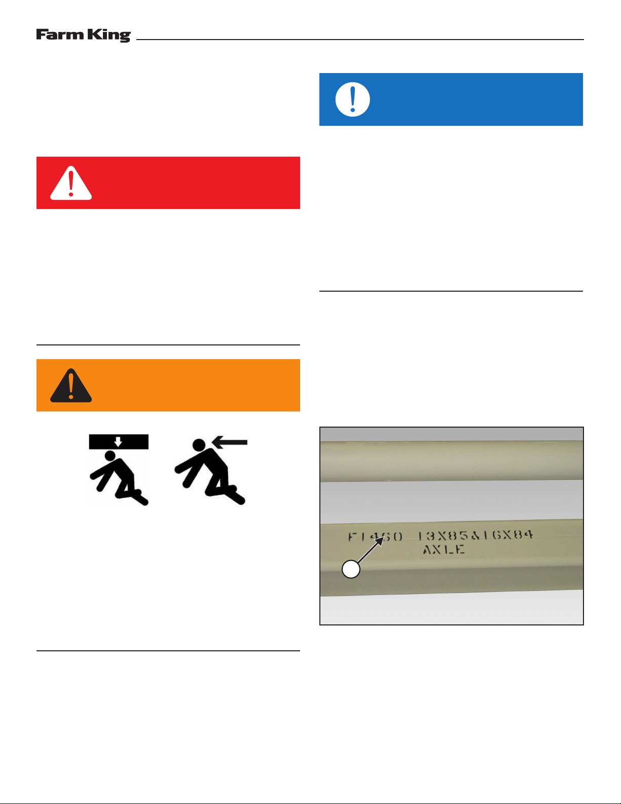
Figure 6
Install a strap (Item 1) around the center of the
axle (Item 2) [Figure 6].
Connect the strap to an approved lifting device.
Raise and move the axle to the assembly area.
Lower the axle to the ground and remove strap.
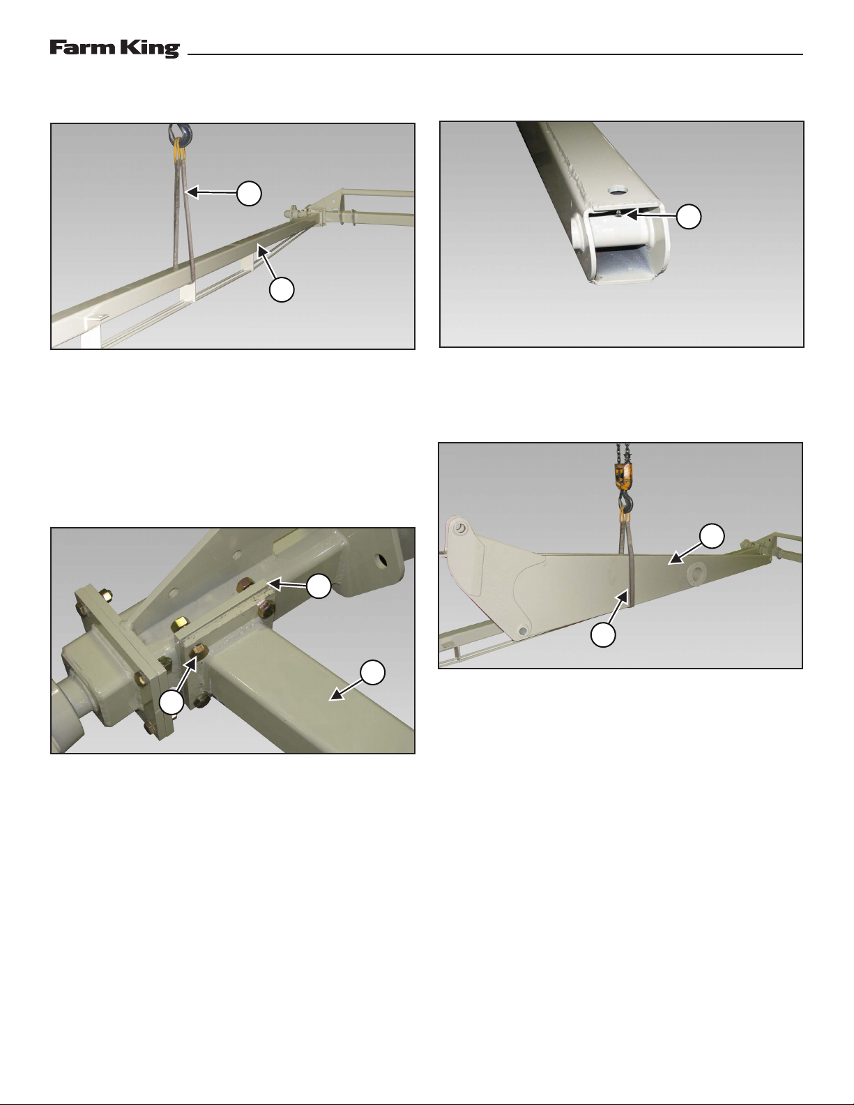
Figure 7
Align the hub (Item 1) with the axle [Figure 7].
Stub Axle Mounting Bolt Sizes:
• 1/2” x 1-3/4” - Models 1370, 1385, 1395
• 3/4” x 2-1/2” - Models 13114
Install and tighten the four bolts (Item 2) and lock
nuts [Figure 7].
Repeat procedure and install the opposite hub
onto the axle [Figure 7].
1
1
2
2

Assembly - 1370, 1385, 1395, 13114 Backsaver Auger
5
Figure 10
Install the grease zerk (Item 1) into the right and
left lower lift arms [Figure 10].
Figure 11
Install a strap (Item 1) around the RH lower lift arm
(Item 2). Connect the strap to an approved lifting
device [Figure 11].
NOTE: Move strap forward or backward until the
component hangs level when raised off
the ground.
Raise and move the RH lower lift arm to the
assembly area.
Figure 8
Install a strap (Item 1) around the center of the
right undercarriage arm (Item 2) [Figure 8].
Connect the strap to an approved lifting device.
Raise and move the right undercarriage arm
towards the axle.
Figure 9
Align the right undercarriage arm (Item 1) with the
mounting flange (Item 2) on the axle [Figure 9].
Undercarriage Arm Mounting Bolt Sizes
• 5/8” x 2” - Models 1370, 1385, 1395
• 3/4” x 2-1/2” - Models 13114
Install four bolts (Item 3) and lock nuts. Do not
tighten bolts and nuts at this time [Figure 9].
1
1
2
2
1
2
3
1

Assembly - 1370, 1385, 1395, 13114 Backsaver Auger
6
Figure 12
Locate the two lift arm axle pins.
Lift Arm Axle Pin Sizes:
• 1” x 5.63” - 1370 Models
• 1” x 6.38” - 1385 & 1395 Models
• 1.25” x 7.259” - 13114 Models
Align the RH lower lift arm (Item 1) with the two
mounts (Item 2) on the axle [Figure 12].
Install one axle pin (Item 3) through the axle
mounts and RH lower lift arm [Figure 12].
Install one 1-1/4” narrow rim washer and 1/4” x 2”
cotter pin (Item 4) onto the axle pin, securing the
RH lower lift arm to the axle [Figure 12].
Install a strap around the LH lower lift arm. Connect
the strap to an approved lifting device.
NOTE: Move strap forward or backward until the
component hangs level when raised off
the ground.
Raise and move the LH lower lift arm to the
assembly area.
Figure 13
Align the LH lower lift arm (Item 1) with the two
mounts (Item 2) on the axle [Figure 13].
Install one axle pin (Item 3) through the axle
mounts and LH lower lift arm [Figure 13].
Install one 1-1/4” narrow rim washer and 1/4” x 2”
cotter pin (Item 4) onto the axle pin, securing the
LH lower lift arm to the axle [Figure 13].
3
1
44
1
3
22

Assembly - 1370, 1385, 1395, 13114 Backsaver Auger
7
Lift Arms and Hydraulic Cylinders - 1370, 1385,
1395 Models
Figure 14
Place the connecting link (Item 1) and pivot yoke
(Item 2) on the ground, between the LH & RH
lower lift arms [Figure 14].
Figure 15
Align the connecting link (Item 1) with LH lower lift
arm (Item 2) [Figure 15].
Connecting Link Pin Sizes:
• 2” x 27 - 15/16” - 1370 Models
• 2” x 34 - 3/16” - 1385 & 1395 Models
Install the connecting link pin (Item 3) through the
LH lower lift arm and connecting link [Figure 15].
Figure 16
Continue installing the connecting link pin through
the connecting link and RH lower lift arm.
Install one 2” x 10 ga. narrow rim washer and one
15/16” x 3” cotter pin (Item 1) onto the connecting
link pin and secure [Figure 16].
Figure 17
Install a chain (Item 1) through the upper LH & RH
lower lift arm mounts. Connect the chain to an
approved lifting device [Figure 17].
Lift the LH & RH lower lift arms. Install blocks (Item
2) under the LH & RH lower lift arms [Figure 17].
NOTE: Verify that there is adequate space under
the LH & RH lower lift arms for installing
the bottom cylinder pin.
Lower the LH & RH lower lift arms onto the blocks.
2
1
1
1
2
3
1
2

Assembly - 1370, 1385, 1395, 13114 Backsaver Auger
8
Figure 18
Rotate the pivot yoke (Item 1) up [Figure 18].
Bottom Cylinder Pin Sizes:
• 1-1/2” x 12-3/8” - 1370 Models
• 2” x 14-13/16” - 1385 & 1395 Models
Align the pivot yoke and connecting link. Install
the bottom cylinder pin (Item 2) through the
connecting link and first side of the pivot yoke
[Figure 18].
Figure 19
NOTE: It is recommended to leave the plastic on
the hydraulic cylinders during assembly.
This will help to prevent damage to the
paint and minimize touch-up painting.
Install a chain or strap (Item 1) through the base
end of the hydraulic cylinder. Connect the chain or
strap to an approved lifting device [Figure 19].
Raise and move the hydraulic cylinder to the
assembly area.
Figure 20
Lower the hydraulic cylinder and align the rod end
of the cylinder with the pivot yoke (with grease
zerks facing as shown).
Continue installing the bottom cylinder pin (Item
1) through the connecting link and opposite side
of the pivot yoke [Figure 20].
Narrow Rim Washer Sizes:
• 1-1/2” x 10 Ga. - 1370 Models
• 2” x 10 Ga. - 1385 & 1395 Models
Cotter Pin Sizes:
• 1/4” x 2” - 1370 Models
• 5/16” x 3” - 1385 & 1395 Models
Install one 2” narrow rim washer (Item 2) and one
cotter pin (Item 3) onto the bottom cylinder pin
[Figure 20].
NOTE: Do not remove chain from base end of the
cylinder.
11
3
2
1
2

Assembly - 1370, 1385, 1395, 13114 Backsaver Auger
9
Figure 21
Lift the LH & RH lower lift arms. Remove blocks
(Item 1). Lower LH & RH lower lift arms to the
ground [Figure 21].
Remove chain (Item 2) [Figure 21].
Figure 22
Install a strap (Item 1) around the lift arm torque
tube (Item 2). Connect the strap to a second
approved lifting device [Figure 22].
Raise and move the lift arm torque tube to the
assembly area.
Align the lift arm torque tube with the LH & RH
lower lift arm mounting plates. Install one 1/2” flat
washer on two 1/2” x 2” bolts (Item 3), install the
two bolts through the top holes (both ends). Install
one 1/2” flat washer and 1/2” lock nut on the bolts
[Figure 22].
Figure 23
Install one 1/2” flat washer on the remaining 1/2”
x 2” bolts (Item 1), install bolts through the lift arm
torque tube and LH & RH lower lift arm mounting
plates. Install 1/2” flat washers and 1/2” lock nuts
(both sides). Do not tighten bolts and lock nuts at
this time [Figure 23].
Remove the strap.
Figure 24
Align the cradle rest (Item 1) with the two mounting
plates on the lift arm torque tube [Figure 24].
Install the four 5/8” x 3-1/2” bolts (Item 2) and 5/8”
lock nuts [Figure 24].
NOTE: Install the cradle rest with the tabs (Item 3)
towards the axle [Figure 24].
2
2
1
3
2
1
1
2
3
3

Assembly - 1370, 1385, 1395, 13114 Backsaver Auger
10
Figure 25
Lower the hydraulic cylinder (Item 1) onto the
cradle rest (Item 2) [Figure 25].
Rotate the cylinder 180° or until the hydraulic
fitting ports are facing down.
Figure 26
Install a strap (Item 1) around the upper lift arm
(Item 2). Connect the strap to an approved lifting
device [Figure 26].
Raise and move the upper lift arm to the assembly
area.
Figure 27
Align and lower the upper lift arm (Item 1) until
the upper lift arm is inside the two mounts (Item
2) on the lower lift arms [Figure 27].
Lower Lift Arm Pin Sizes:
• 1-1/2” x 7-1/8” - 1370 Models
• 2” x 9-1/16” - 1385 & 1395 Models
Narrow Rim Washer Sizes:
• 1-1/2” x 10 Ga. - 1370 Models
• 2” x 10 Ga. - 1385 & 1395 Models
Cotter Pin Sizes:
• 1/4” x 2” - 1370 Models
• 5/16” - 3” 1385 & 1395 Models
Install the two lift arm pins (Item 3) (from the
inside) [Figure 27].
2
2
1
1 1
33
2
2
1

Assembly - 1370, 1385, 1395, 13114 Backsaver Auger
11
Figure 28
Install one 2” narrow rim washer (Item 1) and
cotter pin (Item 2) on the lift arm pin (both pins)
[Figure 28].
Lower the upper lift arm onto the cradle rest.
Figure 29
Install a strap (Item 1) on the upper cross member
of the connecting link [Figure 29].
Lift and align the connecting link with the mounts
(Item 2) on the upper lift arm (Item 3) [Figure 29].
Figure 30
Install the top yoke pin (Item 1) through the upper
lift arm mounting holes (Item 2) and pivot yoke
mounting holes (Item 3) [Figure 30].
Top Yoke Pin Sizes:
• 1-1/2” x 13-11/16” - 1370 Models
• 1-1/2” x 16-11/16” - 1385 & 1395 Models
Remove the strap from the pivot yoke.
Figure 31
Install one narrow rim washer (Item 1) and cotter
pin (Item 2) onto the top yoke pin [Figure 31].
Narrow Rim Washer Sizes:
• 1-1/2” x 10 Ga. - 1370 Models
• 1-1/2” x 10 Ga. - 1385 & 1395 Models
Cotter Pin Sizes:
• 1/4” x 2” - 1370 Models
• 1/4” x 2” 1385 & 1395 Models
2
1231
1
32
2
3
2
1
2

Assembly - 1370, 1385, 1395, 13114 Backsaver Auger
12
Figure 32
Align the base end of the hydraulic cylinder with
the mounting holes of the upper lift arm.
Top Cylinder Pin Sizes:
• 1-1/2” x 8-11/16” - 1370 Models
• 2” x 9” - 1385 & 1395 Models
Install the cylinder pin (Item 1) through the upper
lift arm and cylinder [Figure 32].
Narrow Rim Washer Sizes:
• 1-1/2” x 10 Ga. - 1370 Models
• 2” x 10 Ga. - 1385 & 1395 Models
Cotter Pin Sizes:
• 1/4” x 2” - 1370 Models
• 5/16” x 3” 1385 & 1395 Models
Figure 33
Install one narrow rim washer (Item 1) and cotter
pin (Item 2) onto the cylinder pin, securing the
cylinder to the upper lift arm [Figure 33].
Lift Arms and Hydraulic Cylinders - 13114
Models
Figure 34
Place the connecting link (Item 1) on the ground,
at the front of the RH lower lift arm (Item 2) [Figure
34].
Figure 35
NOTE: It is recommended to leave the plastic on
the hydraulic cylinders during assembly.
This will help to prevent damage to the
paint and minimize touch-up painting.
Install a chain or strap (Item 1) through the rod
end of the two hydraulic cylinders. Connect the
strap to an approved lifting device [Figure 35].
Raise and move the two hydraulic cylinders to the
assembly area.
1
1
1
2
1
2

Assembly - 1370, 1385, 1395, 13114 Backsaver Auger
13
Figure 36
Raise the hydraulic cylinders (Item 1) and move
the two cylinders on the back side of the link (Item
2). Lower the cylinders to the ground and remove
the chain or strap [Figure 36].
Align the two rod ends of the cylinders with the
link (with grease zerks facing up).
Figure 37
Install one 2” narrow rim washer (Item 1) and one
5/16” x 3” cotter pin (Item 2) onto the 2” x 18-7/8”
lift pin rod (Item 3) [Figure 37].
Figure 38
Place the left yoke arm (Item 1) on the outside of
the link (Item 2). Position cylinder inside the link
and opposite side of the yoke arm [Figure 38].
Install the lift pin rod (Item 3) through the left yoke
arm, link and cylinder (stop when the pin enters
the center mount of the link) [Figure 38].
2
2
1
3
1
3
1
1
2

Assembly - 1370, 1385, 1395, 13114 Backsaver Auger
14
Figure 39
Place the right yoke arm (Item 1) on the outside of
the link (Item 2). Position cylinder inside the link
and opposite side of the yoke arm [Figure 39].
Install the lift pin rod (Item 3) through the right
yoke arm, cylinder and link [Figure 39].
Install one 2” narrow rim washer (Item 4) and
one 5/16” x 3” cotter pin to secure the yoke arms,
cylinders and link together [Figure 39].
Figure 40
Install one 1/2” x 3-1/2” bolt (Item 1) through one
end of the 2 3/4” x 39” connecting yoke pin (Item
2), then install one 1/2” lock nut onto the bolt
[Figure 40].
Figure 41
Align the RH lower lift arm (Item 1), link (Item 2)
and LH lower lift arm (Item 3) [Figure 41].
Install the 2-3/4” x 39” connecting yoke pin (Item
4) through the LH lower lift arm, link and RH lower
lift arm [Figure 41].
Figure 42
Install one 1/2” x 3-1/2” bolt (Item 1) through one
end of the 2-3/4” x 39” connecting yoke pin (Item
2), then install one 1/2” lock nut onto the bolt
[Figure 42].
3
2
4
1
1
24
3
1
1
1
2

Assembly - 1370, 1385, 1395, 13114 Backsaver Auger
15
Figure 43
NOTE: Install a chain or strap through the base
ends of the hydraulic cylinders. Connect
the chain or strap to an approved lifting
device. Raise the hydraulic cylinders
above the RH & LH lower lift arms before
installing the lift arm torque tube.
Install a strap (Item 1) around the lift arm torque
tube (Item 2). Connect the strap to a second
approved lifting device [Figure 43].
Raise and move the lift arm torque tube to the
assembly area.
Align the lift arm torque tube with the LH & RH
lower lift arm mounting plates. Install one 1/2” x
2” bolt (Item 3) through the top holes (both ends).
Install one 1/2” flat washer and 1/2” lock nut on
the bolts [Figure 43].
Figure 44
Install the remaining 1/2” x 2” bolts (Item 1), 1/2”
flat washers and 1/2” lock nuts (both sides). Do not
tighten bolts and lock nuts at this time. Remove
the strap [Figure 44].
Figure 45
Align the cradle rest (Item 1) with the two mounting
plates on the lift arm torque tube [Figure 45].
Install the four 5/8” x 3-1/2” bolts (Item 2) and 5/8”
lock nuts [Figure 45].
Figure 46
Lower the two hydraulic cylinders onto the cradle
rest.
Rotate each cylinder 180° or until the hydraulic
fitting ports (Item 1) are facing down [Figure 46].
3
1
1
1
2
3
1
2

Assembly - 1370, 1385, 1395, 13114 Backsaver Auger
16
Figure 47
Install a strap (Item 1) around the upper lift arm
(Item 2). Connect the strap to an approved lifting
device [Figure 47].
Raise and move the upper lift arm to the assembly
area.
Move the upper lift arm over the lower lift arms.
Figure 48
Align and lower the upper lift arm (Item 1) until
the upper lift arm is inside the two mounts (Item
2) on the lower lift arms [Figure 48].
Install the two 2” x 5/8” lift arm pins (Item 3) (from
the inside) [Figure 48].
Figure 49
Install one 2” narrow rim washer (Item 1) and
5/16” x 3” cotter pin (Item 2) on the lift arm pin
(both sides) [Figure 49].
Lower the upper lift arm onto the cradle rest.
Figure 50
Install one 2” narrow rim washer (Item 1) and 5/16
x 3” cotter pin (Item 2) onto the 2” x 20-1/2” upper
lift arm pin rod (Item 3) [Figure 50].
1
2
1
3
2
2
1
2
1
3

Assembly - 1370, 1385, 1395, 13114 Backsaver Auger
17
Figure 51
Install a chain through the mounting hole of the
left yoke arm (Item 1). Lift the left yoke arm until
the right yoke arm (Item 2) (lift right yoke arm by
hand) is aligned with the upper lift arm mounting
hole (Item 3) [Figure 51].
Install the upper lift arm pin rod (Item 4) through
the upper lift arm mounting hole and right yoke
arm [Figure 51].
Remove the chain from the left yoke arm. Lift the
left yoke arm and install the upper lift arm pin
rod through the left yoke arm and upper lift arm
mounting hole.
Figure 52
Install one 2” narrow rim washer (Item 1) and 5/16
x 3” cotter pin onto the 2” x 20-1/2” upper lift arm
pin rod [Figure 52].
Figure 53
Install one 2” narrow rim washer (Item 1) and
5/16 x 3” cotter pin (Item 2) onto the 2” x 17-1/4”
cylinder pin rod (Item 3) [Figure 53].
Figure 54
Align the left cylinder mounting holes of the upper
lift arm.
Install the cylinder pin rod (Item 1) through the
upper lift arm and left cylinder (stop when the
pin enters the center mount of the upper lift arm)
[Figure 54].
2
1
1
1
1
3
2
4
3

Assembly - 1370, 1385, 1395, 13114 Backsaver Auger
18
Figure 55
Using a bar (Item 1), align the right cylinder with
the mounting holes of the upper lift arm [Figure
55].
Continue installing the cylinder pin rod through
the upper lift arm and right cylinder.
Figure 56
Install one 2” narrow rim washer (Item 1) and 5/16”
x 3” cotter pin onto the cylinder pin rod, securing
the cylinders to the upper lift arm [Figure 56].
Wheels and Lift Arm Rest
Figure 57
Install a strap (Item 1) around the center brace (Item
2) on the axle. Connect the strap to an approved
lifting device. Raise the axle high enough to install
the tires [Figure 57].
Figure 58
Install the tires with the valve stem (Item 1) facing
out [Figure 58].
Models 1370, 1385 and 1395: Install six wheel
bolts.
Models 13114: Install eight wheel bolts.
Tighten wheel nuts (Item 2) in a criss-cross pattern
[Figure 58].
Torque wheel nuts to 120 lb. / ft. (162 N•m).
Lower the axle and tires to the ground. Remove
the strap and lifting device. Check tire pressure.
Recommended tire pressure is 45 - 50 PSI (310 -
345 kpa). Maximum tire pressure of 60 PSI (415
kpa).
1
1
1
2
2
1
Other manuals for 1370
2
This manual suits for next models
3
Table of contents
Other Farm King Tools manuals
Popular Tools manuals by other brands

AMES
AMES NEVERLEAK METAL HOSE CABINET-100 FT instructions

Utility Solutions
Utility Solutions BREAK-SAFE USBS-15-1 FIELD INSPECTION PROCEDURE

Central Machinery
Central Machinery 36698 Assembly & operating instructions

VEVOR
VEVOR YL-15T manual

JAMEC PEM
JAMEC PEM PRO X EXTREME-RETRACTABLE operating instructions

Harbor Freight Tools
Harbor Freight Tools HAULMASTER 59665 Owner's manual & safety instructions