SteelMax Li'l Runner User manual


Contents
1. GENERAL INFORMATION ............................................................................................... 3
1.1. Application ................................................................................................................. 3
1.2. Technical data............................................................................................................ 3
1.3. Design ....................................................................................................................... 5
1.4. Equipment included ................................................................................................... 6
2. SAFETY PRECAUTIONS .................................................................................................. 7
3. STARTUP AND OPERATION ........................................................................................... 9
3.1. Preparing ................................................................................................................... 9
3.2. Connecting to welding circuits ...................................................................................10
3.3. Positioning at the worksite ........................................................................................11
3.4. Operating ..................................................................................................................12
3.5. Changing the unit of speed .......................................................................................13
3.6. Troubleshooting ........................................................................................................14
4. MAINTENANCE ...............................................................................................................15
5. ACCESSORIES ...............................................................................................................16
5.1. 16–22 mm torch clamp ..............................................................................................16
5.2. 16–22 mm torch clip ..................................................................................................16
5.3. 22–35 mm torch clamp ..............................................................................................16
5.4. Short rod ...................................................................................................................17
5.5. Long rod....................................................................................................................17
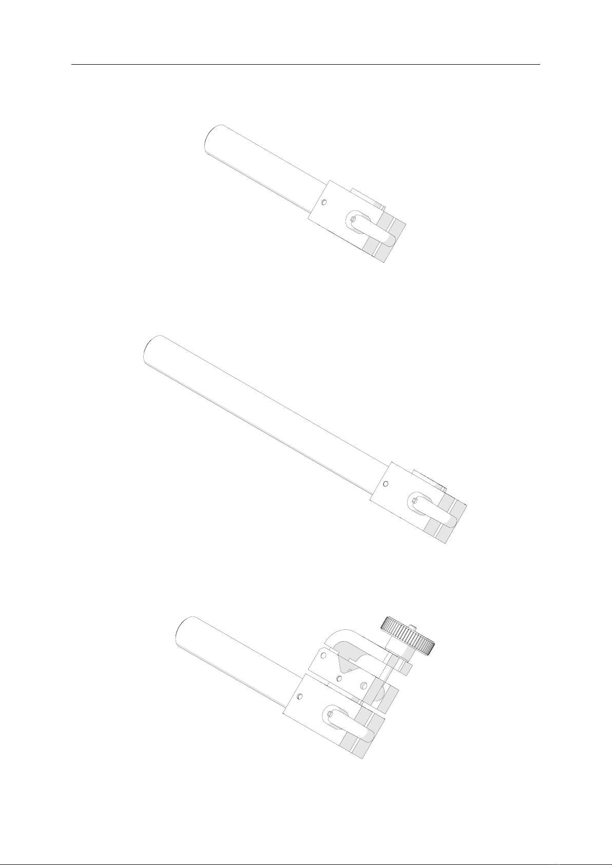
5.6. Short rod torch holder with clamp ..............................................................................17
5.7. Short rod torch holder with clip ..................................................................................18
5.8. Short rod low torch holder with clip ............................................................................18
5.9. Long rod torch holder with clamp ..............................................................................18
5.10. Long rod torch holder with clip ................................................................................19
5.11. Torch extension arm ...............................................................................................19
5.12. Edge following guide arms ......................................................................................20
5.13. Adjustable guide arms ............................................................................................21
5.14. Magnet guide arms .................................................................................................22
5.15. Low guide arms ......................................................................................................23
5.16. High guide arms .....................................................................................................24
5.17. Dual torch mount ....................................................................................................25
5.18. Auxiliary magnet blocks ..........................................................................................26
5.19. Guiding set .............................................................................................................27
5.20. Guide adjustment tool .............................................................................................29
5.21. 76 mm cross slide ...................................................................................................30
5.22. Cable anchor ..........................................................................................................31
6. LI’L RUNNER EXPLODED VIEWS AND PARTS LIST .....................................................32
7. LI’L RUNNER HS EXPLODED VIEWS AND PARTS LIST ...............................................36
8. WIRING DIAGRAM ..........................................................................................................40
9. DECLARATION OF CONFORMITY .................................................................................41
10. QUALITY CERTIFICATE ................................................................................................42
11. WARRANTY CARD ........................................................................................................43
SM-WC-LR Li’l Runner (HS)
Li’l Runner (HS) Operator’s Manual
3
1. GENERAL INFORMATION
1.1. Application
The Li’l Runner (HS) is a welding carriage designed to produce continuous butt and
fillet welds using MIG/MAG torches with the handle diameter of 16–22 mm (0.63–0.87’’).
The carriage is fixed by permanent magnets and can work in the following welding
positions: PA/1F/1G, PB/2F, PC/2G, PD/4F, PE/4G, and PF/3G.
Accessories allow, for instance, using torches with the handle diameter larger
than 22 mm, two torches simultaneously, guiding the carriage along outside edges,
lap joints and templates, walls low or with holes, and on ceilings, pipes, and tanks.
1.2. Technical data
Li’l Runner
Li’l Runner HS
Voltage
1~ 115–230 V, 50–60 Hz
1~ 115–230 V, 50–60 Hz
Power
20 W
20 W
Welding position
(according to
EN ISO 6947 and
AWS/ASME)
horizontal
PA / 1F / 1G
PB / 2F
PC / 2G
PD / 4F
PE / 4G
PA / 1F / 1G
PB / 2F
PC / 2G
PD / 4F
PE / 4G
vertical
PF / 3G
N/A
Minimum path curvature radius
1000 mm (3.5 ft)
1000 mm (3.5 ft)
Torch type
MIG/MAG
MIG/MAG
Torch diameter
16–22 mm (0.63–0.87’’)
16–22 mm (0.63–0.87’’)
Maximum torch reach
70 mm (2.76’’)
70 mm (2.76’’)
Maximum permitted
cable weight
horizontal work
8 kg (18 lbs)
8 kg (18 lbs)
vertical work
6 kg (13 lbs)
N/A
Minimum workpiece thickness
4 mm (0.16’’)
4 mm (0.16’’)
Ground clearance
4 mm (0.16’’)
4 mm (0.16’’)
Horizontal pulling force
150 N (33 lbs)
150 N (33 lbs)
Vertical pulling force
100 N (22 lbs)
N/A
Cross slide adjustment range
0–35 mm (0–1.38’’)
up-down, left-right
0–35 mm (0–1.38’’)
up-down, left-right
Guide arm adjustment range
0–100 mm (0–3.93’’)
0–100 mm (0–3.93’’)
Horizontal speed
0–110 cm/min
(0–43.3 in/min)
5–220 cm/min
(1.5–86.6 in/min)
Vertical speed
0–100 cm/min
(0–39.4 in/min)
N/A
Weight
8 kg (18 lbs)
8 kg (18 lbs)
SM-WC-LR Li’l Runner (HS)
Li’l Runner (HS) Operator’s Manual
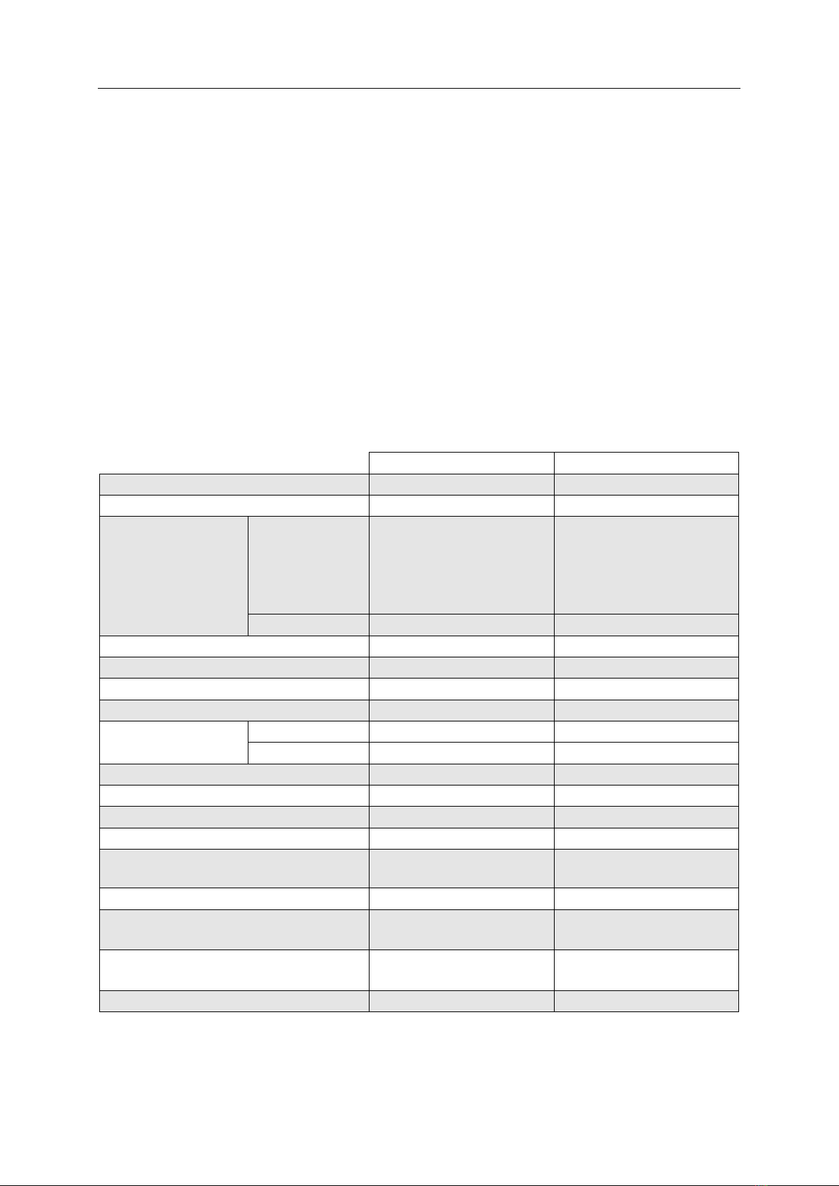
4
320 mm (12.6’’)
277 mm (10.9’’)
366 mm (14.4’’)

SM-WC-LR Li’l Runner (HS)
Li’l Runner (HS) Operator’s Manual
5
1.3. Design
The Li’l Runner (HS) welding carriage consists of a chassis, a drive system, a controller,
a cross slide, two guide arms, and a torch holder. The drive system contains a
gear-motor that drives four rubber wheels.
Permanent magnets fitted at the carriage bottom ensure proper clamping to
ferromagnetic surfaces. The cross slide allows for precise control of the torch holder
position in both the horizontal and vertical axis, and connecting the arc ignition cable
will enable the carriage to ignite an arc when selecting a travel direction.
Fig. 1. View of the Li’l Runner (HS)
Safety line lug
Cross slide
Torch holder
Guide arm
Power switch
Arc ignition socket
Magnet ON/OFF lever
Control panel

SM-WC-LR Li’l Runner (HS)
Li’l Runner (HS) Operator’s Manual
6
Fig. 2. View of the control panel
1.4. Equipment included
The Li’l Runner (HS) is supplied including the following elements.
Carriage
1 unit
Foam filled cardboard box
1 unit
Long rod torch holder with clip
1 unit
3 m (10 ft) power cord
1 unit
6.5 m (21 ft) arc ignition cable
1 unit
4 mm hex wrench
1 unit
Operator’s Manual
1 unit
LED display
Travel direction switch (Left / O / Right)
Arc ignition switch (TEST / O / I)
Speed adjustment knob

SM-WC-LR Li’l Runner (HS)
Li’l Runner (HS) Operator’s Manual
7
2. SAFETY PRECAUTIONS
1. Before beginning, read this Operator’s Manual and complete proper occupational
safety and health training.
2. Use the carriage only in applications specified in this Operator’s Manual.
3. The carriage must be complete and all parts must be genuine and fully operational.
4. The specifications of the power source must conform to those specified on the rating
plate.
5. Plug the carriage into a properly grounded power source.
6. Never carry the carriage by the cords or arc ignition cable and never pull them as
this may damage them and result in electric shock.
7. Untrained bystanders must not be present near the carriage.
8. Before beginning, make sure that the correct is the condition of the carriage, power
source, cords, arc ignition cable, plugs, control panel, and wheels.
9. Keep the carriage dry. Exposure to rain, snow, or frost is prohibited.
10. Keep the work area well lit, clean, and free of obstacles.
11. Never use near flammable liquids or gases, or in explosive environments.
12. Make sure that the rubber of the wheels is clean and not damaged.
13. Never disassemble the cover of the wheels.
14. Remove objects attracted to the chassis by the magnet.
15. Transport and position the carriage using the carrying handle and only when the
magnet ON/OFF lever is set to the position ‘O’.
16. Position the carriage on the ferromagnetic workpiece in such a way that the wheels
are in contact with the surface and there is no contact between the surface and
the chassis.
17. Do not stay below the carriage placed at heights.
18. Plug the cords and arc ignition cable only when the power switch is set to the
position ‘O’.
19. Keep the sockets clean. Do not use compressed air for cleaning.
20. Install only MIG/MAG torches with the handle diameter corresponding to the
torch holder in use.
21. Position the torch not more than 70 mm (2.76’’) outward from the left or right side
of the carriage.

SM-WC-LR Li’l Runner (HS)
Li’l Runner (HS) Operator’s Manual
8
22. Keep the torch cables from coming in contact with the surface. They must be
suspended to reduce the load of the carriage. Use only cables whose weight is
not more than 8 kg (18 lbs) for horizontal work and 6 kg (13 lbs) for vertical work.
23. Operating on curvatures with a convex or concave radius less than 1000 mm
(3.5 ft) is prohibited.
24. Operate the HS version of the carriage in horizontal positions only.
25. When operating at heights, use a safety line to protect the carriage from dropping.
26. Always use eye protection (helmet, shield, and screen), hearing protection, gloves,
and protective clothing during operation. Do not wear loose clothing.
27. Before every use, inspect the carriage to ensure it is not damaged. Check whether
any part is cracked or improperly fitted. Make sure to maintain proper conditions
that may affect the operation of the carriage.
28. Never try to manually stop the motion of the carriage. To stop, set the travel
direction switch to the position ‘O’.
29. Maintain only when the carriage is unplugged from the power source.
30. Repair only in a service center appointed by the seller.
31. If the carriage falls from any height, is wet, or has any other damage that could
affect the technical state of the carriage, stop the operation and immediately send
the carriage to the service center for inspection and repair.
32. Never leave the carriage unattended during operation.
33. Remove from the worksite and store in a secure and dry location when not in use.

SM-WC-LR Li’l Runner (HS)
Li’l Runner (HS) Operator’s Manual
9
3. STARTUP AND OPERATION
3.1. Preparing
Use the carrying handle to transport the carriage to the worksite. Then, set to the
position ‘O’ all the switches (power, travel direction, and arc ignition switch) and
the magnet lever. Next, connect the carriage to the power source, and then insert the
torch into the torch holder and secure with the screws.
Fig. 3. View from the back side
Precise torch position adjustment knobs
Levers securing
the torch position and angle
Screws securing the torch in the holder
Screw securing the guide arm
Carrying handle
SM-WC-LR Li’l Runner (HS)
Li’l Runner (HS) Operator’s Manual
10
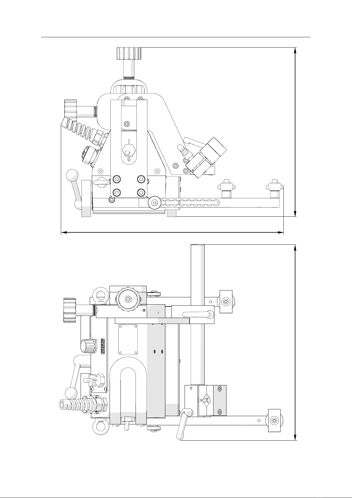
3.2. Connecting to welding circuits
The carriage can control two torches using the arc ignition cable plugged into the arc
ignition socket. To do this, connect any blue-jacketed wire to any terminal of the welding
circuit, and then connect the second blue-jacketed wire to the second terminal of the
same circuit, according to the diagram shown in Fig. 4. To control the second torch,
connect the green-jacketed wires to the terminals of the second welding circuit.
Fig. 4. Connecting the arc ignition cable to welding circuits
To check whether the arc ignition cable is connected correctly, power the carriage
by setting the power switch to the position ‘I’, and set the arc ignition switch to the
position TEST, which should enable the arc for a while.
blue
blue
Welding circuit 1
green
green
Welding circuit 2

SM-WC-LR Li’l Runner (HS)
Li’l Runner (HS) Operator’s Manual
11
3.3. Positioning at the worksite
Move out the right guide arm 10 mm (0.4’’) more than the left guide arm (Fig. 5),
which will keep the carriage in constant contact with the workpiece when the carriage
travels to the left. To do this, use the 4 mm hex wrench to loosen the screw securing
the guide arm, set the guide arm properly, and then retighten the screw.
The guide arms can be set continuously or by a constant step. To switch between
these two methods, change the left guide arm with the right guide arm.
Fig. 5. Proper position of the guide arms
Switch the magnet ON/OFF lever from left (‘O’) to right (‘I’), which will change the
clamping force from minimum to maximum. Loosen the levers to adjust the position
and angle of the torch, and set the torch position precisely using two knobs located at
the cross slide. When operating at heights, attach a safety line to the lug to prevent
possible injury if the carriage loses the clamping. The safety line is not included in
standard equipment.
Travel direction

SM-WC-LR Li’l Runner (HS)
Li’l Runner (HS) Operator’s Manual
12
3.4. Operating
After setting the power switch to the position ‘I’ the carriage will turn on, which will
illuminate all segments of the display ( ). After a while, the indication will change
to if the unit of speed is set to centimeters per minute, or to for inches per
minute. Then, the carriage speed will show. The speed can be adjusted by rotating
the knob located on the panel. If the carriage is to control the torch, set the arc ignition
switch to the position ‘I’.
Use the travel direction switch to select a direction of motion, which will start the
movement of the carriage with the speed shown on the display. To stop the motion,
set the travel direction switch to the position ‘O’.
After the work is finished, turn off the carriage using the power switch and unplug
the carriage from the power source.
CAUTION! If the arc ignition switch is set to position ‘I’, the torch
will start welding immediately after selecting a travel direction.

SM-WC-LR Li’l Runner (HS)
Li’l Runner (HS) Operator’s Manual
13
3.5. Changing the unit of speed
To change the unit of speed from centimeters per minute to inches per minute, or
vice versa, unplug the power cord from the power source and follow the steps shown
in Fig. 6.
Fig. 6. Changing the unit of speed
After changing the unit and powering the carriage again, the actual measurement
unit will show. When the jumper cap connects the left and center pin, the display
shows and the speed is given in centimeters per minute. When the jumper cap
connects the center and right pin, the display shows message and the speed is
indicated in inches per minute.
The 2.5 mm hex wrench needed to unscrew the control panel is not included in
standard equipment.
Place the jumper cap in the position
corresponding to the required unit.
cm
inch
Use the 2.5 mm hex wrench to loosen
the fixing screws to access the back
side of the control panel.

SM-WC-LR Li’l Runner (HS)
Li’l Runner (HS) Operator’s Manual
14
3.6. Troubleshooting
Message
Problem
Solution
Not all display segments illuminated
after powering indicate a problem with
the display or controller.
Contact service center for inspection
and repair.
Speed displayed in centimeters per
minute instead of inches per minute.
Follow instructions given in the
section “Changing the unit of speed.”
Speed displayed in inches per minute
instead of centimeters per minute.
Follow instructions given in the
section “Changing the unit of speed.”
1. Travel direction switch not in
position ‘O’ when powering.
2. Displayed during motion indicates
a malfunction of the travel direction
switch or travel direction identification
circuit of the controller.
1. Set the travel direction switch to the
position ‘O’. If the message still
appears, contact service center for
inspection and repair.
2. Contact service center for
inspection and repair.
Motor overload (safe current level
exceeded) causing the immediate
stop of the carriage.
Use welding cables that do not
exceed maximum weight specified in
technical data.
Adjust the arrangement of the cables
that block the motion of the carriage.
Remove any other elements that
block the carriage or its wheels.
If this message still appears, contact
service center for inspection and
repair.

SM-WC-LR Li’l Runner (HS)
Li’l Runner (HS) Operator’s Manual
15
4. MAINTENANCE
Daily:
1. Clean the chassis and the wheels.
2. Clean the rollers of the guide arms and make sure that the rollers rotate freely.
3. Clean the torch nozzle. Replace if damaged.
Monthly:
1. Check whether the knob and the switches operate as intended. Replace if loose
or damaged.
2. Inspect cables, cords, and hoses. Replace if damaged.
3. Tighten screws if loose.
SM-WC-LR Li’l Runner (HS)
Li’l Runner (HS) Operator’s Manual
16
5. ACCESSORIES
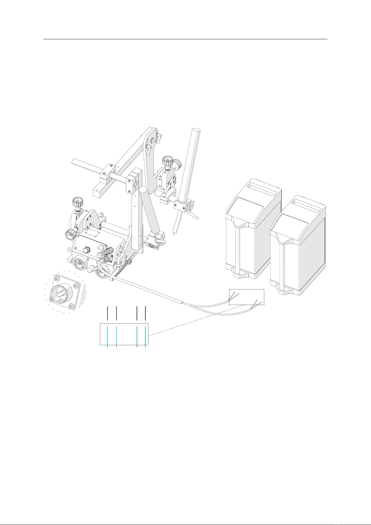
5.1. 16–22 mm torch clamp
Allows using a torch with the handle diameter of 16–22 mm (0.63–0.87’’).
5.2. 16–22 mm torch clip
Allows using a torch with the handle diameter of 16–22 mm (0.63–0.87’’). Tighten the
torch in the clip using the 4 mm hex wrench.
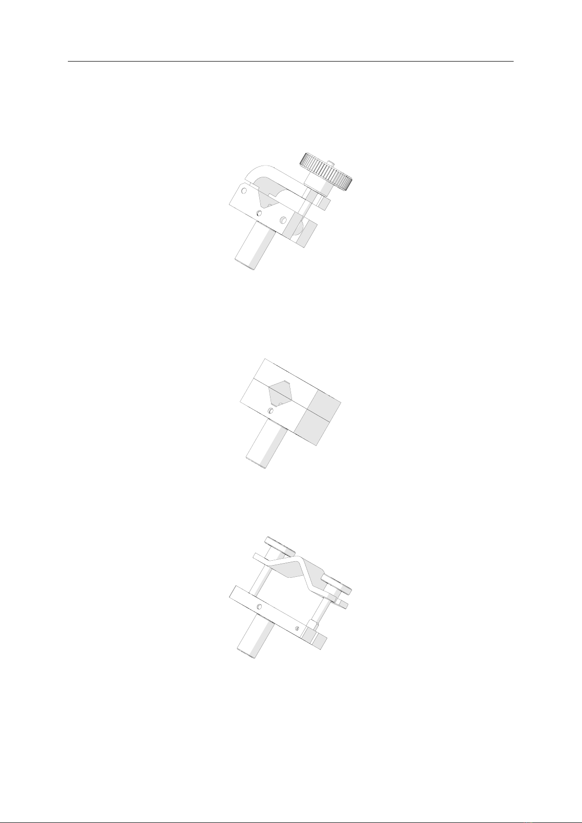
5.3. 22–35 mm torch clamp
Allows using a torch with the handle diameter of 22–35 mm (0.87–1.38’’).
Part number:
ZRZ-0466-19-00-00-0
Part number:
ZRZ-0466-04-01-00-0
Part number:
ZCS-0476-06-01-00-0
SM-WC-LR Li’l Runner (HS)
Li’l Runner (HS) Operator’s Manual
17
5.4. Short rod
Provides a 120 mm (4.72’’) reach.
5.5. Long rod
Provides a 240 mm (9.45’’) reach.
5.6. Short rod torch holder with clamp
Allows using a torch with the handle diameter of 16–22 mm (0.63–0.87’’).
Part number:
UCW-0476-20-00-00-0
Part number:
WLK-0476-20-01-00-0
Part number:
WLK-0466-04-10-00-0
SM-WC-LR Li’l Runner (HS)
Li’l Runner (HS) Operator’s Manual
18
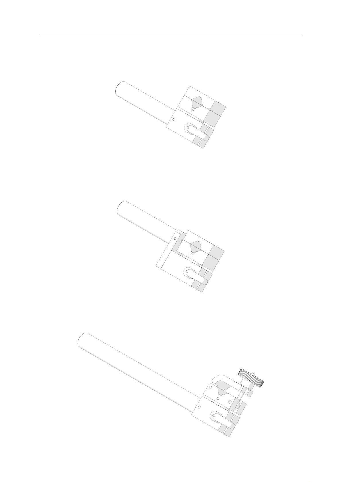
5.7. Short rod torch holder with clip
Allows using a torch with the handle diameter of 16–22 mm (0.63–0.87’’). Tighten the
torch in the clip using the 4 mm hex wrench.
5.8. Short rod low torch holder with clip
Allows using a torch with the handle diameter of 16–22 mm (0.63–0.87’’). Tighten the
torch in the clip using the 4 mm hex wrench.
5.9. Long rod torch holder with clamp
Allows using a torch with the handle diameter of 16–22 mm (0.63–0.87’’).
Part number:
UCW-0466-04-00-00-0
Part number:
UCW-0476-27-00-00-0
Part number:
UCW-0476-06-00-00-0

SM-WC-LR Li’l Runner (HS)
Li’l Runner (HS) Operator’s Manual
19
M5x16
M5x10
Part number:
PRD-0466-43-00-00-0
5.10. Long rod torch holder with clip
Allows using a torch with the handle diameter of 16–22 mm (0.63–0.87’’). Tighten the
torch in the clip using the 4 mm hex wrench.
5.11. Torch extension arm
Extends the reach of the torch. To install the arm, unscrew the M5x10 screws fixing
the cross slide using the 4 mm hex wrench and use the same screws to fix the cross
slide at the end of the arm as shown in the figure. Fix the arm to the carriage using
M5x16 screws.
Part number:
UCW-0466-22-00-00-0
SM-WC-LR Li’l Runner (HS)
Li’l Runner (HS) Operator’s Manual
20
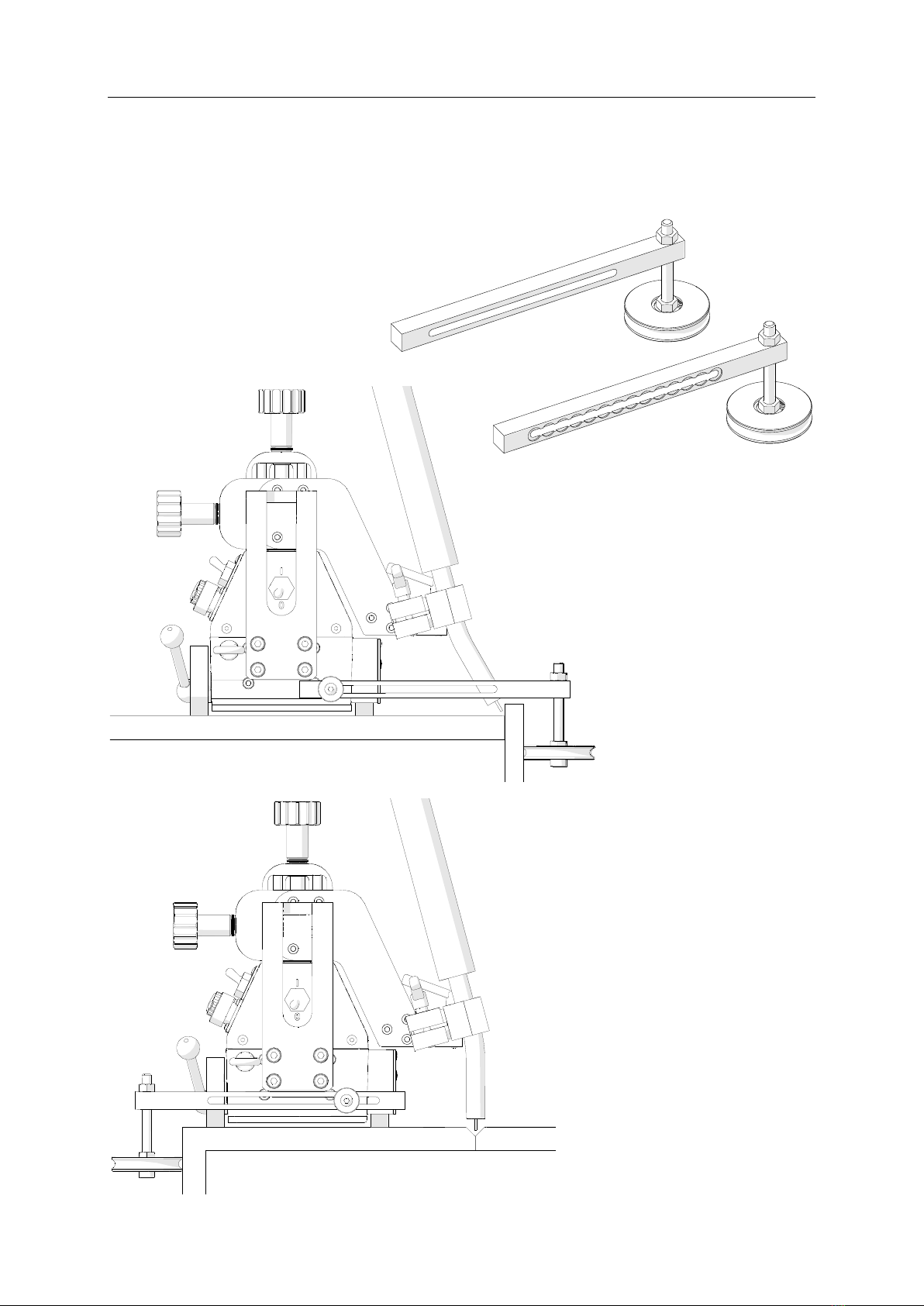
5.12. Edge following guide arms
Allow guiding the carriage along outside edges. Install the guide arms after unscrewing
the standard guide arms using the 4 mm hex wrench.
Part number (2 units):
PRW-0466-41-00-00-1
This manual suits for next models
1
Table of contents
Other SteelMax Welding System manuals


Popular Welding System manuals by other brands


Thermal Dynamics
Thermal Dynamics MERLIN 6000 Service manual

Thermal Arc
Thermal Arc POWERMASTER 320SP Service manual

Craftsman
Craftsman 117-076 user guide

CHIEF
CHIEF MultiMig 521 instruction manual

Scheppach
Scheppach WSE860 Translation of original operating manual

Clarke
Clarke MMA140A Operation & maintenance instructions