SteelMax Rail Runner User manual
The tools of innovation.
15335 E. Freemont Drive, Centennial,CO 80112
1–87STEELMAX, FAX 303 –690 –9172
www.steelmax.com [email protected]
OPERATOR’S MANUAL
R
Ra
ai
il
l
R
Ru
un
nn
ne
er
r
WELDING CARRIAGE

Contents
1. GENERAL INFORMATION............................................................................................... 3
1.1. Application................................................................................................................. 3
1.2. Technical data............................................................................................................ 3
1.3. Equipment included ................................................................................................... 4
1.4. Dimensions................................................................................................................ 5
1.5. Design ....................................................................................................................... 6
2. SAFETY PRECAUTIONS.................................................................................................. 7
3. STARTUP AND OPERATION........................................................................................... 9
3.1. Assembling the track.................................................................................................. 9
3.2. Assembling the holder...............................................................................................11
3.3. Positioning................................................................................................................12
3.4. Connecting to the welding circuits.............................................................................13
3.5. Operating..................................................................................................................14
3.6. Changing the unit of measure...................................................................................16
3.7. Troubleshooting........................................................................................................17
4. MAINTENANCE...............................................................................................................18
5. ACCESSORIES...............................................................................................................19
5.1. Semi-flex track..........................................................................................................19
5.2. Rigid track.................................................................................................................19
5.3. Rack adjustment tool.................................................................................................19
5.4. Magnetic units...........................................................................................................20
5.5. Semi-flex track support .............................................................................................24
5.6. Transport attachment................................................................................................24
5.7. 76 mm cross slide.....................................................................................................25
5.8. Vacuum track system................................................................................................26
5.9. Torch holders, clamps, and rods...............................................................................27
6. 115–230 V WIRING DIAGRAM........................................................................................29
7. 42 V WIRING DIAGRAM..................................................................................................30
8. 115–230 V EXPLODED VIEWS AND PARTS LIST..........................................................31
9. 42 V EXPLODED VIEWS AND PARTS LIST ...................................................................36
10. DECLARATION OF CONFORMITY...............................................................................41
11. WARRANTY CARD........................................................................................................42

Rail Runner
Rail Runner Operator’s Manual
3
1. GENERAL INFORMATION
1.1. Application
The Rail Runner is a track carriage designed to make butt and fillet welds with or
without oscillation by using MIG/MAG torches. The track is fixed by using magnetic
units to ferromagnetic surfaces that are flat or curved.
Accessories allow using torches with a larger diameter and guiding the carriage
on a semi-flex or rigid track. Using a vacuum track system allows the track to be
clamped to surfaces that are non-ferromagnetic.
1.2. Technical data
Voltage
1~ 115–230 V, 50–60 Hz
1~ 42 V, 50–60 Hz (60 V DC)
Power
100 W
Welding position
(according to EN ISO 6947
and AWS/ASME)
Horizontal
PA/1F/1G
PB/2F
PC/2G
PD/4F
PE/4G
Vertical
PF/3G
PG/3F (contact your dealer)
PG/3G
Minimum curve radius of a semi-flex track
5 m (16 ft)
Torch type
MIG/MAG
Torch diameter
16–22 mm (0.63–0.87″)
Minimum workpiece thickness for magnetic
clamping
5 mm (0.2″)
Horizontal pulling force
350 N (77 lbs)
Vertical pulling force
150 N (33 lbs)
Cross slide adjustment range
0–35 mm (0–1.38″, up-down, left-right)
Horizontal speed
0–120 cm/min (0–47.2 in/min)
Vertical speed
0–110 cm/min (0–43.3 in/min)
Oscillation type
Linear
Oscillation path
Trapezoid, triangle, straight line
Oscillator arm stroke
0–100 mm (0–3.9″)
Oscillation width
0–50 mm (0–1.9″)
Oscillation speed
0–1500 mm/min (0–59 in/min)
Oscillation dwell time at center and on ends
0–5 s
Maximum oscillator pulling force
100 N (22 lbs)
Maximum allowed ambient temperature
50°C (122°F)
Maximum allowed ambient humidity
85%
Weight
20 kg (44 lbs)
Rail Runner
Rail Runner Operator’s Manual
4
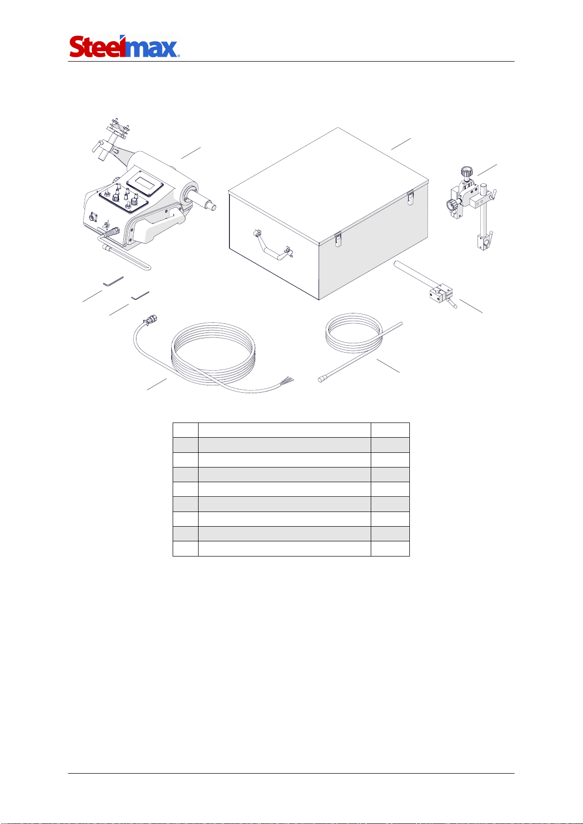
1.3. Equipment included
1
Carriage
1 unit
2
Metal box
1 unit
3
Cross slide assembly
1 unit
4
Long rod torch holder with clip
1 unit
5
3 m (10 ft) power cord
1 unit
6
6.5 m (21 ft) arc ignition cable
1 unit
7
3 mm hex wrench
1 unit
8
4 mm hex wrench
1 unit
–
Operator’s Manual
1 unit
1
2
3
4
5
6
7
8

Rail Runner
Rail Runner Operator’s Manual
5
1.4. Dimensions
362 mm
(14.3’ ’ )
644 mm
(25.4’ ’ )
441 mm (17.4’’)
Rail Runner
Rail Runner Operator’s Manual
6
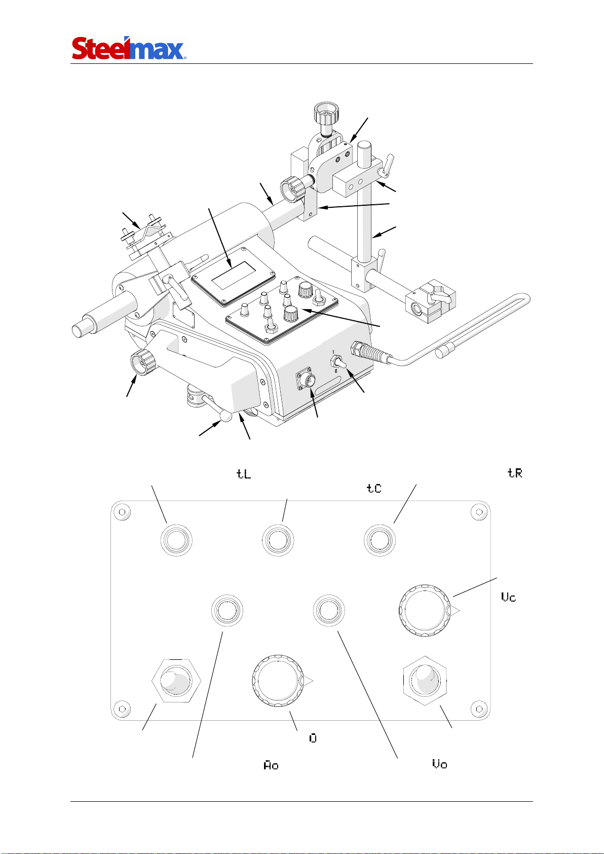
1.5. Design
Oscillation width knob
Oscillation speed knob
Arc ignition switch
(TEST / O / I)
Travel direction switch
(Forward / O / Backward)
Oscillation offset knob (arm stroke)
Travel
speed
knob
Left oscillation position dwell knob
Right oscillation position dwell knob
Center oscillation position dwell knob
Pressing lever
Control
panel
Oscillator arm
Cable anchor
Cross slide
Power switch
Arc ignition socket
Drive clutch knob
Display
Carrying handle
Clamping block
Long rod

Rail Runner
Rail Runner Operator’s Manual
7
2. SAFETY PRECAUTIONS
1. Before use, read this Operator’s Manual and complete a training in occupational
safety and health.
2. Use only in applications specified in this Operator’s Manual.
3. Make sure that the carriage has all parts and they are genuine and not damaged.
4. Make sure that the specifications of the power source are the same as those
specified on the rating plate.
5. Connect the carriage to a correctly grounded power source.
6. Do not carry the carriage by the cords or arc ignition cable, and do not pull them.
This can cause damage and electric shock.
7. Keep untrained bystanders away from the carriage.
8. Before each use, ensure the correct condition of the carriage, power source,
cords, arc ignition cable, plugs, control panel, rollers, and gear.
9. Before each use, make sure that no part is cracked or loose. Make sure to
maintain correct conditions that can have an effect on the operation of the
carriage.
10. Keep the carriage dry. Do not expose the carriage to rain, snow, or frost.
11. Keep the work area well lit, clean, and free of obstacles.
12. Do not use near flammable materials, or in explosive environments.
13. Transport and position the carriage by using the carrying handles.
14. Install the carriage only on the supplied track.
15. Make sure that the gear and rollers are clean.
16. Connect the cords and the arc ignition cable only after you set the power switch
to ‘O’.
17. Keep the sockets clean. Do not use high pressure during cleaning.
18. Install only torches whose diameter matches the diameter of the torch holder.
19. Hang the cables to decrease the load applied on the carriage.
20. Do not bend the semi-flex track to a radius less than 5 m (16 ft).
21. Use the rigid track only on flat surfaces.
22. At heights, protect the carriage and the track from falling. To do this, use chains
(not included) to attach the leftmost and rightmost magnetic units of the track to a
stable structure. To protect the carriage, attach a chain to a carrying handle.
Make sure that the chains are not loose.

Rail Runner
Rail Runner Operator’s Manual
8
23. Do not stay below the carriage or the track that is put at heights.
24. Use eye protection (helmet, shield, and screen), ear protection, gloves, and
protective clothing. Do not use loose clothing.
25. Do not stop the carriage by hand. To stop, set the travel direction switch to ‘O’.
26. Do the maintenance only after you unplug the carriage from the power source.
27. Repair only in a service center appointed by the seller.
28. If the carriage falls, is wet, or has any damage, stop the work and promptly send
the carriage to the service center for check and repair.
29. Do not leave the carriage unattended during work.
30. If you are not going to use the carriage, remove it from the work area and keep in
a safe and dry place.

Rail Runner
Rail Runner Operator’s Manual
9
3. STARTUP AND OPERATION
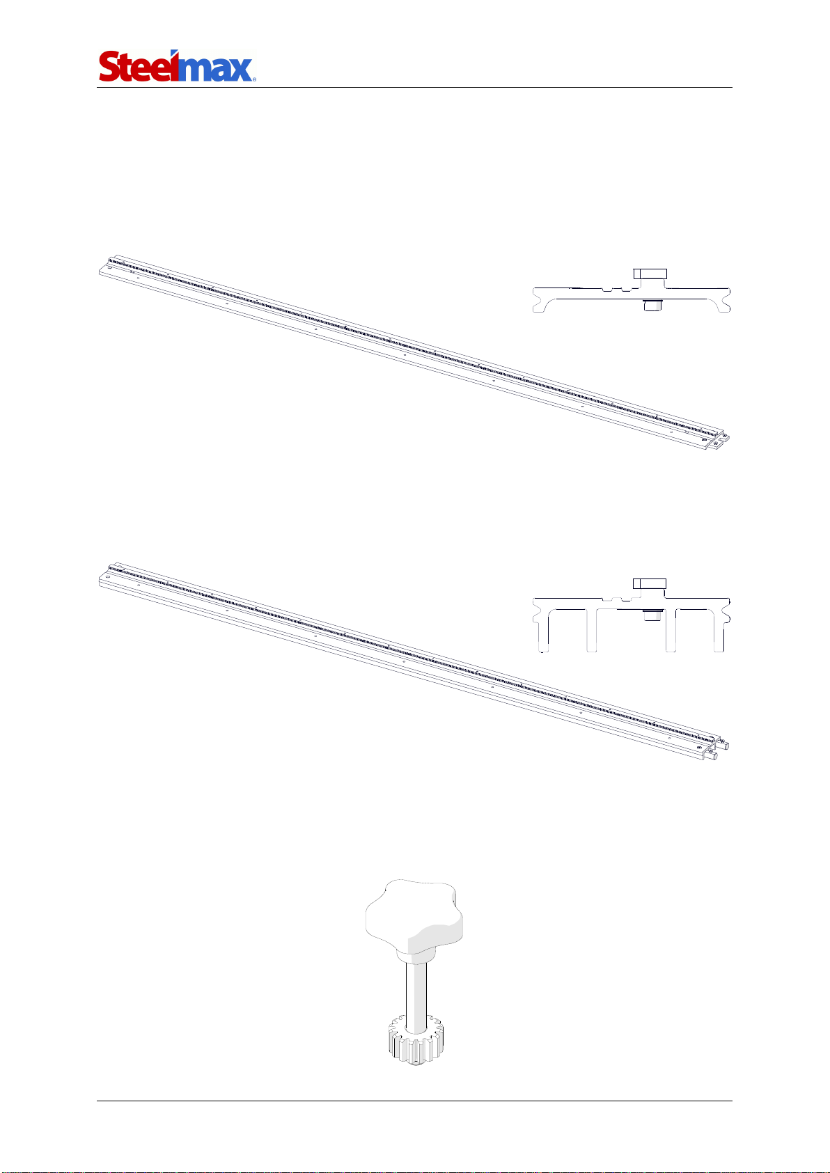
3.1. Assembling the track
Attach magnetic units to the rail, and put it on the workpiece. Use the 4 mm hex
wrench to attach more rails (1, Fig. 1). Then, set the levers of the magnetic units to ‘I’
(2). This will clamp the track to the surface.
When working in PC/2G welding position, put the track so that the teeth of the
racks point down.
Fig. 1. Connecting the rails and clamping the magnetic units to the surface
If a semi-flex rail is put on a curve, before you attach more rails use the 4 mm hex
wrench to loosen the screws of the connecting plates (1, Fig. 2) and of the racks (2).
Next, attach the rails, clamp them with levers, and then tighten the connecting plates.
Put the rack adjustment tool (not included) into the hole (3), and rotate the tool to the
left (4) to remove the gap (5) between the racks. Then, tighten the leftmost screw and
the rightmost screw of each rack (2).
1
2

Rail Runner
Rail Runner Operator’s Manual
10
Fig. 2. Removing the gap between the racks of a semi-flex track
1
2
5
3
4
Rail Runner
Rail Runner Operator’s Manual
11
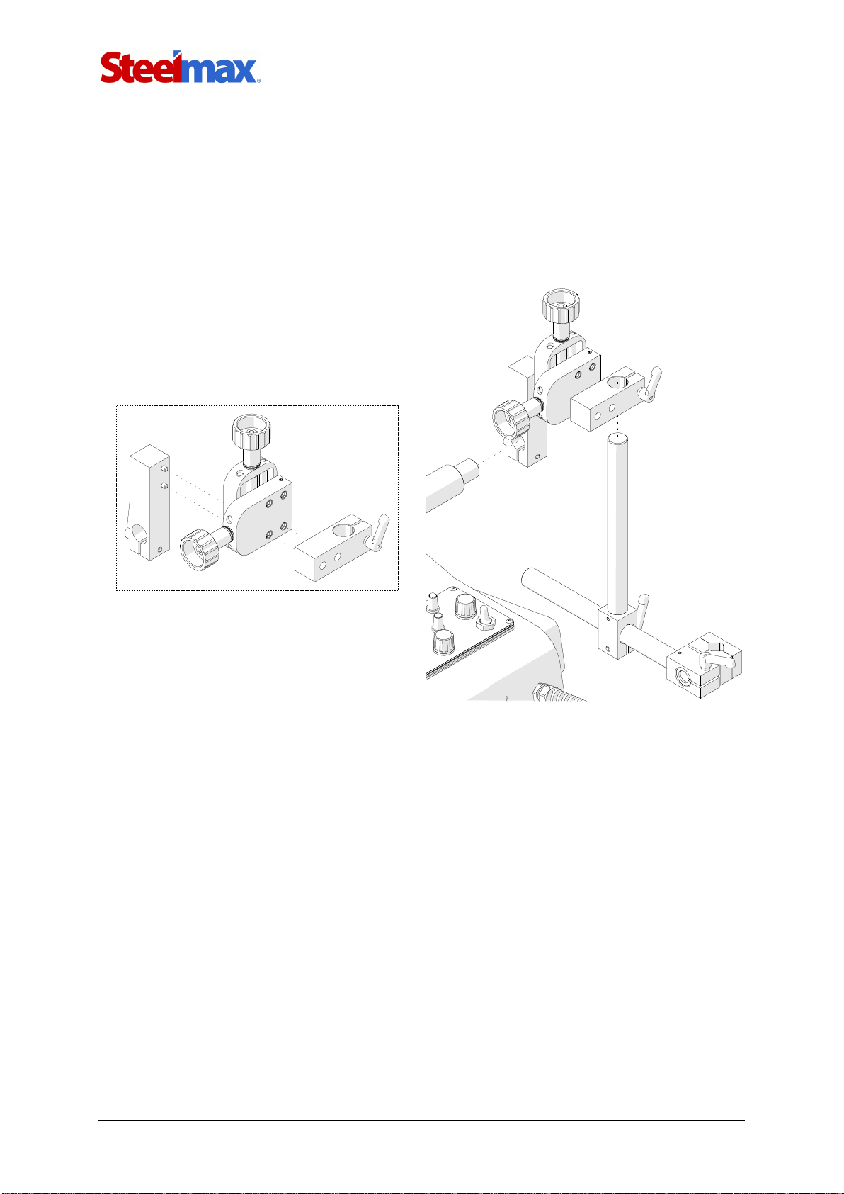
3.2. Assembling the holder
Use the 4 mm hex wrench to attach the clamping blocks to the cross slide with four
M5x20 screws as shown in Fig. 3. The parts shown can be assembled in many ways
to form different configurations. However, note that the oscillator moves in and out
during startup. Thus, to allow correct startup, install the torch holder and the cross
slide so that they will not collide with the carriage side or obstacles.
Fig. 3. Sample method of assembling the torch holder
Rail Runner
Rail Runner Operator’s Manual
12
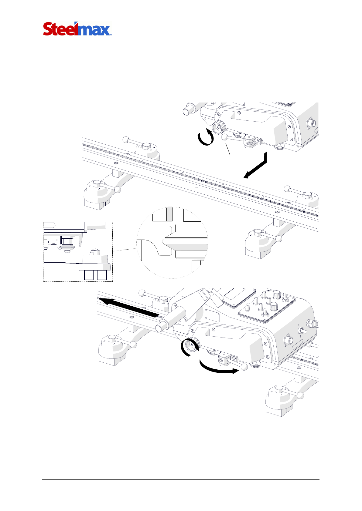
3.3. Positioning
Set the power switch, arc ignition switch, and travel direction switch to ‘O’. Next, set
the lever to OFF (1, Fig. 4), and then loosen the knob (2) fully. Then, put the carriage
onto the track (3) so that the back rollers are in the groove (4).
Fig. 4. Putting the carriage on the track
1
2
3
7
6
5
4

Rail Runner
Rail Runner Operator’s Manual
13
Set the lever to ON (5) to press the front rollers to the track. Move the carriage to
the required position (6), and fully tighten the knob (7) to engage the gear of the
carriage with the rack of the rail. Then, loosen the knob by 1/4 rotation.
At heights, protect the carriage and the track from falling. To do this, use chains
(not included) to attach the leftmost and rightmost magnetic units of the semi-flex or
rigid track to a stable structure. To protect the carriage, attach a chain to a carrying
handle. Make sure that the chains are not loose.
Connect the carriage to the power source. Then, put the torch and torch cables
into the holders.
3.4. Connecting to the welding circuits
The carriage can control two torches by using the arc ignition cable plugged into the
arc ignition socket. To do this, refer to the diagram from Fig. 5 and connect one
blue-jacketed wire to one terminal of the welding circuit. Then, connect the other
blue-jacketed wire to the other terminal of the same circuit. To control the second
torch, connect the green-jacketed wires to the terminals of the second welding circuit.
Fig. 5. Connecting the arc ignition cable to welding circuits
Make sure that the arc ignition cable is connected correctly. To do this, turn on the
power of the carriage, and then set the arc ignition switch to TEST. This should
enable the arc for a while.
Blue
Blue
Welding circuit 1
Green
Green
Welding circuit 2
Rail Runner
Rail Runner Operator’s Manual
14
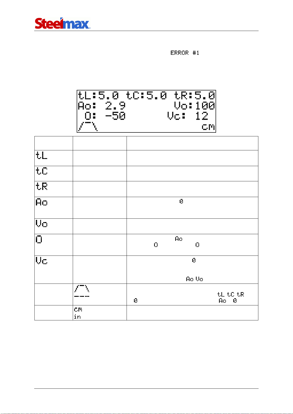
3.5. Operating
Set the power switch to ‘I’ to turn on the carriage. If shows on the display,
set the travel direction switch to ‘O’. Then, use the knobs on the control panel to set
the required process parameters (Tab. 1). Right rotation increases the value of the
parameter. Left rotation decreases the value.
Parameter
Value
Description
0–5 s
[step: 0.1]
Dwell time in left position of the oscillation.
0–5 s
[step: 0.1]
Dwell time in center position of the oscillation.
0–5 s
[step: 0.1]
Dwell time in right position of the oscillation.
0–5 cm
0–2 in
[step: 0.1 cm/0.02 in]
Oscillation width. Set to weld without oscillation.
0–100%
[step: 1%]
Relative oscillation speed.
–100% to 100%
[step 1%]
Oscillation offset. If exceeds the value of the
parameter , the parameter is calculated again
automatically.
0
5–140 cm/min
2–55 in/min
Carriage speed. Setting to during travel stops the
main motor. Then, the oscillator goes into the test
mode to allow for correct selection of the width and
speed of the oscillation ( , ).
Welding path
(trapezoid)
(straight line)
Trapezoid is default. To weld according to the
triangular pattern, set all dwell times ( , , )
to . To weld along a straight line, set to .
Unit
Unit set by the jumper cap (Fig. 7).
Tab. 1. Configuration parameters
Rail Runner
Rail Runner Operator’s Manual
15
To control the torch through the carriage, set the arc ignition switch to ‘I’.
If the arc ignition switch is set to ‘I’, the torch starts welding
promptly after you select a travel direction.
Use the travel direction switch to select a direction of travel. Then, the travel
starts with the parameters shown on the display. You can adjust the parameters with
the knobs at any time.
The produced welds have a shape similar to that shown in Fig. 6.
Fig. 6. Graphic description of the oscillation parameters from Tab. 1
To stop the travel and save the values shown on the display, set the travel
direction switch to ‘O’.
After the work is finished, use the power switch to turn off the carriage. Then,
unplug the carriage from the power source.
Weld start
Weld end
1 /
Rail Runner
Rail Runner Operator’s Manual
16
3.6. Changing the unit of measure
To change the unit of measure between centimeters and inches, unplug the carriage
from the power source and follow the steps shown in Fig. 7.
Fig. 1. Changing the unit of measure
When the jumper cap connects the top and center pin, the measurement system
will be metric after restart. When the jumper cap connects the center and bottom pin,
the system will be imperial.
Put the jumper cap in the position
that matches the required unit.
Use the 2.5 mm hex wrench (not included)
to loosen the screws and get access to the
back side of the control panel.
inch
cm
Rail Runner
Rail Runner Operator’s Manual
17
3.7. Troubleshooting
Message
Problem
Solution
Travel direction switch not set to ‘O’
when powering.
Set the travel direction
switch to ‘O’.
Malfunction of the direction switch wire set
or the controller.
Contact service center for
check and repair.
Power not supplied to the main motor
or malfunction of the main motor encoder.
Contact service center for
check and repair.
Oscillator move blocked or power not
supplied to the oscillator motor.
Remove obstacles that block
the oscillator. If this message
still shows, contact service
center for check and repair.
Malfunction of the oscillator motor
encoder or the controller.
Contact service center for
check and repair.
Malfunction of the oscillator sensor.
Contact service center for
check and repair.
Malfunction of the encoder board.
Contact service center for
check and repair.

Rail Runner
Rail Runner Operator’s Manual
18
4. MAINTENANCE
Each day:
1. Clean the gear of the carriage and the rack of each rail.
2. Clean the rollers. Make sure that the rollers rotate freely.
3. Clean the torch nozzle and replace if damaged.
Each month:
1. Make sure that the knobs and the switches work as intended. Replace if they
are loose or damaged.
2. Examine cables and cords, and replace if damaged.
3. Tighten screws if loose.
Rail Runner
Rail Runner Operator’s Manual
19
5. ACCESSORIES
5.1. Semi-flex track
Allows guiding the carriage along a curve. The length of a single rail is 2 m (6.5 ft).
The minimum bend radius is 5 m (16.5 ft).
5.2. Rigid track
Allows guiding the carriage along a straight line. The length of a single rail is 2 m (6.5
ft).
5.3. Rack adjustment tool
Removes the clearance between the racks of two semi-flex rails that are put on
a curve.
Part number:
PRW-0482-15-05-00-0
Part number:
PKT-0341-13-00-00-0
Part number:
PRW-0482-47-00-00-0

Rail Runner
Rail Runner Operator’s Manual
20
5.4. Magnetic units
5.4.1. Magnetic unit
Allows clamping a semi-flex or rigid track to ferromagnetic surfaces.
Holding force on a
5 mm (0.2″) thick surface
Temperature
Magnetic unit
Heat-resistant magnetic unit
100% (1200 N)
20°C (68°F)
20°C (68°F)
75% (900 N)
80°C (176°F)
160°C (320°F)
50% (600 N)
120°C (248°F)
200°C (392°F)
Use the 4 mm hex wrench to attach the unit to the tracks as shown in the figures.
Part number
(bracket for semi-flex track):
DYS-0482-19-00-00-0
Part number
(bracket for rigid track):
DYS-0482-21-00-00-0
Part number:
ZSP-0475-44-00-00-0 (magnetic unit)
ZSP-0475-44-00-00-1 (heat-resistant magnetic unit)
M6x20
M6x16
M6x16
M6x35
6.4
6.4
Other manuals for Rail Runner
1
Table of contents
Other SteelMax Welding System manuals


 Operator's manual")


