SteelMax Rail Runner LT User manual
The tools of innovation.
15335 E. Freemont Drive, Centennial, CO 80112
1–87STEELMAX, FAX 303 –690 –9172
www.steelmax.com [email protected]
OPERATOR’S MANUAL
R
Ra
ai
il
l
R
Ru
un
nn
ne
er
r
L
LT
T
WELDING CARRIAGE

Contents
1. GENERAL INFORMATION............................................................................................... 3
1.1. Application................................................................................................................. 3
1.2. Technical data............................................................................................................ 3
1.3. Equipment included ................................................................................................... 4
1.4. Dimensions................................................................................................................ 5
1.5. Design ....................................................................................................................... 6
2. SAFETY PRECAUTIONS.................................................................................................. 7
3. STARTUP AND OPERATION........................................................................................... 9
3.1. Assembling the hi-flex, semi-flex, or rigid track........................................................... 9
3.2. Assembling the ring track..........................................................................................11
3.3. Positioning on a straight track...................................................................................13
3.4. Positioning on a curved track....................................................................................15
3.5. Preparing..................................................................................................................16
3.6. Connecting to the welding or plasma cutting circuits.................................................18
3.7. Operating..................................................................................................................19
3.8. Adjusting the pressure of rollers................................................................................20
3.9. Troubleshooting........................................................................................................21
4. MAINTENANCE...............................................................................................................22
5. ACCESSORIES...............................................................................................................23
5.1. MIG/MAG welding set...............................................................................................23
5.2. SAW welding set.......................................................................................................23
5.3. Oxy-fuel cutting set...................................................................................................24
5.4. Plasma cutting set.....................................................................................................24
5.5. Hi-flex track...............................................................................................................25
5.6. Semi-flex track..........................................................................................................26
5.7. Rigid track.................................................................................................................26
5.8. Rack adjustment tool.................................................................................................26
5.9. Magnetic units...........................................................................................................27
5.10. Semi-flex track support............................................................................................32
5.11. Vacuum track system..............................................................................................33
5.12. Ring tracks..............................................................................................................34
5.13. Ring track supports and bracket..............................................................................36
5.14. Rack........................................................................................................................37
5.15. Torch holders, clamps, and rods.............................................................................38
5.16. Cutting torch holders...............................................................................................40
5.17. Gas manifold (for oxy-fuel cutting)...........................................................................42
6. WIRING DIAGRAM..........................................................................................................44
7. EXPLODED VIEWS AND PARTS LIST............................................................................45
8. DECLARATION OF CONFORMITY.................................................................................49
9. WARRANTY CARD..........................................................................................................50
Rail Runner LT
Rail Runner LT –Operator’s Manual
3
1. GENERAL INFORMATION
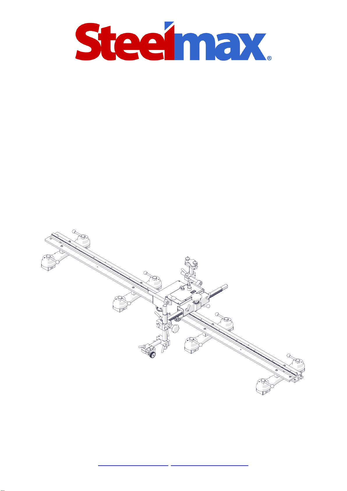
1.1. Application
The Rail Runner LT is a track carriage designed to cut and to make butt and fillet
welds. Allows MIG/MAG, SAW, oxy-fuel, or plasma torches. The track is clamped
with magnetic units to ferromagnetic surfaces that are flat or curved.
Accessories allow using torches with a larger diameter, and guiding the carriage
on a hi-flex, semi-flex, rigid, or ring track. Using a vacuum track system allows the
track to be clamped to surfaces that are non-ferromagnetic.
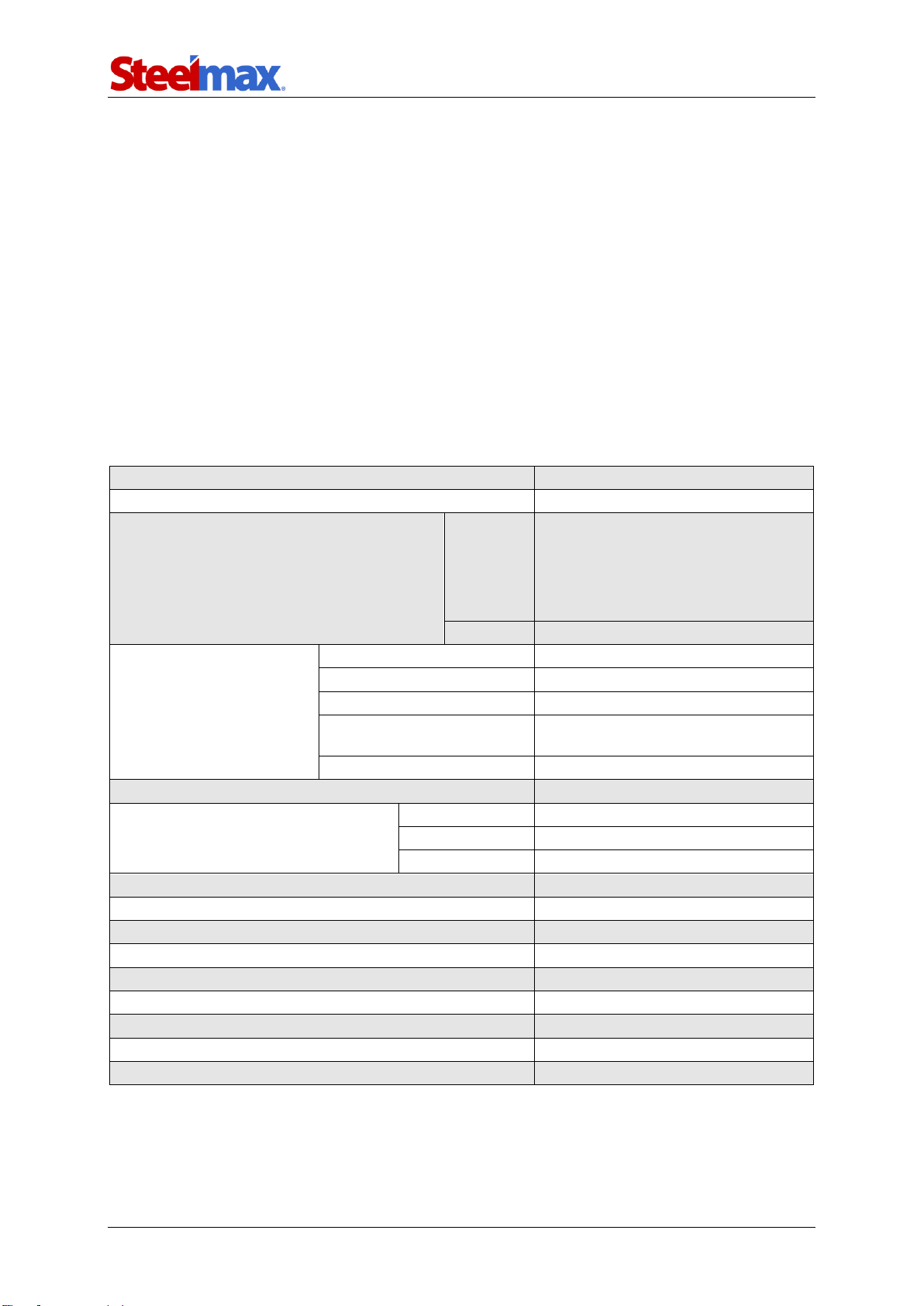
1.2. Technical data
Voltage
1~ 115–230 V, 50–60 Hz
Power
66 W
Welding position
(according to EN ISO 6947 and
AWS/ASME)
Horizontal
PA/1F/1G
PB/2F
PC/2G
PD/4F
PE/4G
Vertical
PG/3F (contact your dealer)
Diameter
of round workpiece
Ring tracks (OD)
200 mm (8″) – 3 m (10 ft)
Hi-flex tracks (OD)
Minimum 1.5 m (5 ft)
Hi-flex tracks (ID)
Minimum 3.4 m (11 ft)
Custom rolled tracks (OD)
3–10 m (10–32 ft)
(contact your dealer)
Semi-flex tracks (OD)
Minimum 10 m (32 ft)
Torch type
MIG/MAG, SAW, oxy-fuel, plasma
Torch diameter
MIG/MAG
16–22 mm (0.63–0.87″)
SAW, plasma
28–35 mm (1.10–1.38″)
Oxy-fuel
35 mm (1.38″)
Minimum workpiece thickness for magnetic clamping
5 mm (0.2″)
Horizontal pulling force
300 N
Vertical pulling force
200 N
Horizontal speed
10–200 cm/min (4–80 in/min)
Vertical speed
10–200 cm/min (4–80 in/min)
Allowed ambient temperature
0–50°C (32–122°F)
Maximum allowed ambient humidity non-condensing
80%
Protection level
IP 23
Weight
10 kg (22 lbs)
Rail Runner LT
Rail Runner LT –Operator’s Manual
4
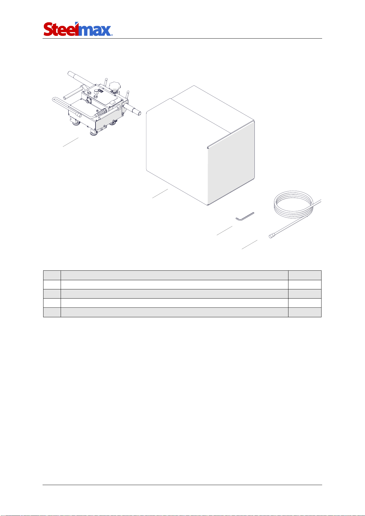
1.3. Equipment included
1
Carriage with a 540 mm (21″) rack
1 unit
2
Cardboard box
1 unit
3
6 mm hex wrench
1 unit
4
3 m (10 ft) power cord
1 unit
–
Operator’s Manual
1 unit
4
1
3
2

Rail Runner LT
Rail Runner LT –Operator’s Manual
5
1.4. Dimensions
379 mm (14.9″)
713 mm (28.1″)
334 mm (13.1″)
Other manuals for Rail Runner LT
1
Table of contents
Other SteelMax Welding System manuals


Popular Welding System manuals by other brands


Hobart Welding Products
Hobart Welding Products AirForce 375 owner's manual

GF
GF MSA 330 instruction manual

Hakko Electronics
Hakko Electronics FX-888D instruction manual

Abicor Binzel
Abicor Binzel ABIPLAS WELD 100 W operating instructions

EWM
EWM Taurus 355 Basic TDM operating instructions

Thermal Dynamics
Thermal Dynamics PakMaster 100 XL plus operating manual


