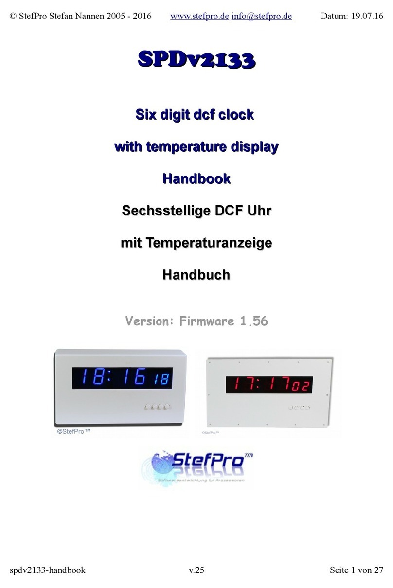
StefPro SPDv2133.01 User manual

SPDv2133.01
Six digit dcf clock
with 4x20mm + 2x14mm red 7 segment LED displays
and temperature
Handbook
Version: Firmware 1.72-131
StefPro UG (haftungsbeschränkt) & Co. KG
Theilenmoorstr. 11
26345 Bockhorn, Germany
Phone: +49-4452-709175
Web: https://www.stefpro.biz/
E-mail: info@stefpro.biz
Handbook Version 1.0.0 - Valid from 10.01.2018.

2
4
5
5
6
6
6
6
7
8
8
8
10
10
10
11
11
11
11
12
12
12
12
12
12
13
13
13
13
13
13
14
14
14
14
14
14
14
15
15
15
15
16
16
16
16
16
16
16
17
17
17
17
17
17
18
19
19
19
19
20
20
20
21
21
Table of Contents
Table of Contents
Safety
Application and function description
Function description
Technical data
Construction description
Installation of the device (Dimensions)
Connectors
X-DC : DC Power input : DC plug 2,1mm, 2 pins
Installation the DCF clock
Synchronize with active display
Synchronize with deactivated display
Button description
Overview of buttons
Menu
Normal
Display mode of clock
Show Temperature
Alarm
Alarm enable
Alarm time hour
Alarm time minute
Alarm snooze time
Alarm sound wait time
Alarm maximum time
Alarm exit
Brightness
Brightness menu
Brightness max
Brightness min
Brightness automatically
Brightness speed
Brightness factor
Brightness offset
Exit brightness settings
DCF
Receiving brightness
Receiving brightness
Receive state display
DCF input pull up
DCF input invert
Power save pin invert
DCF sensitivity
DCF exit
Clock Settings
Set hour
Set minute
Set year
Set month
Set day
Set time
Exit clock settings
Info section
IC number
Firmware version
Menu end
Attachment
Bootloader handling
Start the IC/module/device in bootloader mode
Use the Firmware Upload Tool to upload an update
7 segment characters
Change log
Safety
DCF module properties
Set day
StefPro - www.stefpro.biz - info@stefpro.biz - SPDv2133.01 13.01.2018
Table of Contents - Page 2 of 24

Safety
Follow the manual
The device is only safe in operation if all instructions are read in this handbook.
General understanding of safety
By the device there are no hazard under normal use.
Intended Use
The IC is designed for driving small to middle displays.
The power should come from a safe transformer (also protected transformer) or a corresponding low voltage power supply for the circuit.
Never use a higher voltage or direct mains voltage!
Concealed Hazards
DANGER
following hazards may arise in case of wrong construction of the circuit and wrong handling of device:
With the direct connection to mains, it's a dangerous voltage on the module and other components, use a safety transformer!
Reverse polarity and overloading the device may cause in smoke. This smoke possibly contains toxic substances which must not be
inhaled! Ventilate the room.
Reverse polarity or overload of the device can cause a hot surface on the IC or other component in the circuit.
There is a risk of burning when touching.
And flammable materials, for example Paper, can come in fire.
Despite careful examination, the housing parts can still be sharp and sharp! Therefore, they can cause wounds if handled incorrectly.
Modifications of the example circuit
Check as appropriate all housing part and lines for damage. This applies in particular to parts of the directly (for example power cord and power
supply) or indirectly come into contact with mains voltage.
StefPro - www.stefpro.biz - info@stefpro.biz - SPDv2133.01 13.01.2018
Safety - Page 4 of 24

Application and function descriptionApplication and function description
Function description
This IC can analyze the DCF77 signal, which is received by a receiver and demodulated. Thereceived time and date can output directly to a 7-segment
displays.
The DCF77 signal is a low frequency radio signal which transferred the time and date. It will besent in Frankfurt am Main, derived of the local atomic
clock and sent with the carrier frequencyof 77.5 kHz. Therefore, these watches are also known as radio clock.
The input for the DCF77 antenna can now automatically detect whether a pullup resistor isrequired and whether the input has to be inverted.
Even a simple alarm function is implemented.
This IC has the new OnChip FullMultiPlex Display technology. With this technology also small very weak displays can work and the displays are
generally brighter.
This IC also has an adjustable brightness control for the display, thereby the display is easy toread during the day and at night it does not light out
the entire room.
With this IC the temperature will be displayed alternately with the time and or date.
This IC has a bootloader, which allows you to update the IC firmware.This means that you will always remain at the current state of the Firmware for
the IC, without further costs.
StefPro - www.stefpro.biz - info@stefpro.biz - SPDv2133.01 13.01.2018
Application and function description - Function description Page 5 of 24

Technical data
Operating voltage: 9 - 12 volts DC
Current: 200mA
Power: approximately 1.8 W (at 9 volts)
Volume level of the buzzer: approx. 85 to 90 DB
Construction descriptionConstruction description
Installation of the device (Dimensions)
Figure 1:Installation (Dimensions) description for device SPH2305.0
Place the watch on a level and stable surface.
Connectors
Figure 2:Connector description for device SPH2305.0
Please use a plug-in power supply with a matching socket of 2.1mm, as well as suitable voltage and current specifications. Pin assignment see X-DC.
StefPro - www.stefpro.biz - info@stefpro.biz - SPDv2133.01 13.01.2018
Construction description - Technical data Page 6 of 24

DANGER
Make sure that you have connected all signals correctly. There is no overload and polarity protection!
X-DC : DC Power input : DC plug 2,1mm, 2 pins
Pin Name Direction Function Maximum
Outer GND Power
Inner V+ Power Power supply input of the
module
9 - 12 volts DC, 200mA
StefPro - www.stefpro.biz - info@stefpro.biz - SPDv2133.01 13.01.2018
Construction description - Technical data Page 7 of 24

Installation the DCF clockInstallation the DCF clock
Figure 1: Align the DCF antenna
The external antenna receives the DCF77 signal and should be directed to Frankfurt, as shown in Figure 1.
The antenna should be placed at least 1 meter away from a monitor, computer or other disturbing electronic devices .
During installation, the receiving LED can be used as an orientation to the quality of reception. The LED should flash at intervals of one second.If the
antenna is properly aligned and the signal is strong enough, the display changes of "no signal" (No impeccable DCF77 signal) in "SEArCH" (search for
the 59th second). Was the 59th second found so will the display shows "rEAd60" (read the DCF time) henceforth. It still takes 60 seconds to display
the correct time.If the clock is not synchronized to the DCF time, the receiver LED flashes DCF work cycle (power reserve is in operation), if the LED is
enabled in the menu.Is the display not changed to "SEArCH", the antenna is probably disturbed by a device or the antenna is too close to the
display.Because the DCF antenna is so sensitive that it can disturb by the display in the near field, there is the possibility to reduce the brightness of
the display during the synchronization, or to deactivate the display. This problem have all other DCF clocks with multiplexed LEDs displays also.By a
darker display the DCF antenna can be mounted significantly closer to the display.
Synchronize with active display
This mode is active when in menu under "receive brightness" the brightness is set > 0.
Appearance of the text on the screen:
"no Sig" no signal.
"SEArCH" Search the fifty-ninth second.
"rEAdxx" read the dcf time.
Synchronize with deactivated display
This mode is active when in menu under "receive brightness" the brightness is set to 0.
When synchronizing with disabled display, only one decimal point for orientation appears.
"no Sig" no signal.
StefPro - www.stefpro.biz - info@stefpro.biz - SPDv2133.01 13.01.2018
Installation the DCF clock - Synchronize with active display Page 8 of 24

"SEArCH" Search the fifty-ninth second.
"rEAdxx" read the dcf time.
StefPro - www.stefpro.biz - info@stefpro.biz - SPDv2133.01 13.01.2018
Installation the DCF clock - Synchronize with active display Page 9 of 24

Button descriptionButton description
Overview of buttons
MenuMenu
Level 1 Level 2
Normal⇓⇓
Display mode of
clock⇓⇓
Show
Temperature⇓⇓
Alarm⇓⇓ Alarm enable ➟Alarm time hour ➟Alarm time minute ➟Alarm snooze time ➟Alarm sound wait time ➟Alarm maximum time
➟Alarm exit ↻
Brightness⇓⇓ Brightness menu ➟Brightness max ➟Brightness min ➟Brightness automatically ➟Brightness speed ➟Brightness factor
➟Brightness offset ➟Exit brightness settings ↻
DCF⇓⇓ Receiving brightness ➟Receiving brightness ➟Receive state display ➟DCF input pull up ➟DCF input invert ➟Power save pin
invert ➟DCF sensitivity ➟DCF exit ↻
Clock Settings⇓⇓ Set hour ➟Set minute ➟Set year ➟Set month ➟Set day ➟ ➟Set time ➟Exit clock settings ↻
Info section⇓⇓
IC number⇓⇓
Firmware
version⇓⇓
⇓: Next step in main menu. ➟: Next step in sub menu. ↻: The submenu starts again.
StefPro - www.stefpro.biz - info@stefpro.biz - SPDv2133.01 13.01.2018
Button description - Overview of buttons Page 10 of 24

Normal
Normal mode, outside of the menu.
Here the + button has the function of the alarm temporary switch on or
off.
The - button Switches the display to 100% (flashlight).
Display mode of clock
Sets the mode how to display time and date.
ti: Shows only the time.
dA: Shows only date.
td: Shows time and date alternately.
Show Temperature
Display temperature on
Display temperature off
Enables the temperature display.
Alarm
ALARM
With + you enter the sub-menu Alarm.
StefPro - www.stefpro.biz - info@stefpro.biz - SPDv2133.01 13.01.2018
Button description - Normal Page 11 of 24

Alarm enable
ALARM ON
ALARM OFF
Enables the alarm.
Alarm time hour
Sets the hour for alarm.The number can be 0-23
Alarm time minute
Sets the minutes for alarm.The number can be 0-59
Alarm snooze time Sets the minutes for the snooze function.The number can be 1-30
NOTICE
If "alarm maximum time" is shorter than alarm snooze time, the
snooze function is disabled!
Alarm sound wait time
Alarm sound delay
Sets the maximum time in minutes for the alarm.The number can be 0 -
10.
NOTICE
If "Alarm sound delay" greater selected as maximum alarm time, then
the display is only set to 100% brightness! No buzzer alarm!
Alarm maximum time
Sets the maximum time in minutes for the alarm.The number can be 2-
60.
StefPro - www.stefpro.biz - info@stefpro.biz - SPDv2133.01 13.01.2018
Button description - Normal Page 12 of 24

Alarm exit
With + you exit the sub-menu alarm.
Brightness
Brightness
With + you enter the sub-menu brightness.
Brightness menu
Brightness
Sets the brightness of the menu.The number can be 10-25
Brightness max
Brightness high
In this menu item, the maximum brightness of the display can be
adjusted.
This is also used when auto brightness is disabled.
The number can be 0-25
Brightness min
Brightness low
In this menu item, the minimum display brightness can be adjusted.
The number can be 0-25
Brightness automatically
Brightness automatically on
Brightness automatically off
This allows to turn on and off auto brightness.
StefPro - www.stefpro.biz - info@stefpro.biz - SPDv2133.01 13.01.2018
Button description - Brightness Page 13 of 24

Brightness speed
Brightness speed
This sets the speed of auto brightness.
The number can be 0-10
Brightness factor
Brightness factor
This sets the calculation factor for auto brightness.
The number can be 1-99
Brightness offset
Brightness offset
This sets the calculation offset for auto brightness.
The number can be -99 - 99
Exit brightness settings
With + you exit the sub-menu brightness.
DCF
DCF
With + you enter the sub-menu DCF.
Receiving brightness
Receiving brightness
Sets the brightness during the DCF receiving. If 0, the display is turned
off and the status of the synchronization is shown by decimal points.The
number can be 0-25.
Receiving brightness
DCF synchronize hour
Sets the hour in which the DCF clock will synchronize.The number can
be 0-23.
StefPro - www.stefpro.biz - info@stefpro.biz - SPDv2133.01 13.01.2018
Button description - DCF Page 14 of 24

Receive state display
DCF status decimal point display
Sets the mode for the receive LED, which shows the received signal.The
number can be 0-2.
0: Only until the clock has been synchronized.
1: Shows the received signal when the clock is not synchronized
with the DCF77 signal.
2: Shows the received signal permanently on the receiver LED.
DCF input pull up
DCF input pull up auto
DCF input pull up on
DCF input pull up off
DCF77 input pin with pullup
AU: Pull Up is automatically ( default ).
AU is activated by pressing the + button.
ON: Enables the pull-up resistor
OFF: Disables the pull-up resistor
ON and OFF is activated and toggled by the - button.
Conrad DCF module = ON
ELV DCF module = ON
Pollin DCF module (3.3 V) = OFF
No guarantee for correctness of the information and changes of the
manufacturer.
DCF input invert
DCF input invert auto
DCF input invert on
DCF input invert off
DCF77 inverting the input pin
AU: input is automatically inverted or not (default).
AU is activated by pressing the + button.
ON: Input inverts
OFF: no input invertedON and OFF is activated and toggled by the -
button.
Conrad DCF module = for PIN3 ON, PIN4 OFF
ELV DCF module = ON
Pollin DCF module (3.3 V) = OFF
No guarantee for correctness of the information and changes of the
manufacturer.
If the receive LED is off every second, the setting must be inverted.
Power save pin invert
DCF powersave invert on
DCF powersave invert off
Inverts DCF77 power On / Off output
ON: Power ON / OFF output is inverted (module ON at GND)
OFF: power on / off output is not inverted. (module ON at VCC)
Conrad DCF module = No power on / off input pin available
ELV DCF module = No power on / off input pin available
Pollin DCF module (3.3 V) = ON
No guarantee for correctness of the information and changes of the
manufacturer.
Read the instructions of the receiver module for the power on / off pin
of the DCF module to set this setting correctly. Many modules do not
have this pin, then this setting can be ignored.
StefPro - www.stefpro.biz - info@stefpro.biz - SPDv2133.01 13.01.2018
Button description - DCF Page 15 of 24

DCF sensitivity
DCF sensitivity
Sets the DCF Sensitivity. 1 has a very low tolerance and 6 has the highest
tolerance for reception. The Sensitivity should be set as small as
possible to avoid incorrect receiving.The number can be 1-6
DCF exit
DCF Exit
With + you exit the sub-menu DCF
Clock Settings
With + you enter the sub-menu clock.
Set hour
Set the hour.
The number can be 0-23.
Set minute
Set the minute.
The number can be 0-59.
Set year
Sets the year.
The number can be 2000-2099.
Set month
Sets the month.
The number can be 1-12.
StefPro - www.stefpro.biz - info@stefpro.biz - SPDv2133.01 13.01.2018
Button description - Clock Settings Page 16 of 24

Set day
Set the day, limit by month.
The number can be 1- 28, 29, 30, 31.
MISSING: MENU_CODE_L2_DATECLOCK_GET_WDATE
Set time
Sets the time, while looking for DCF time, otherwise the time will be
provided directly.
Exit clock settings
With + you exit the sub-menu clock. Until here the clock, without DCF
synchronization, will be taken and used until the next scheduled
synchronization.
Info section
This indicates the start the information area
IC number
Chip number
IC / device type
Firmware version
Firmware version
Firmware version
Example, it might be something else at this point.
StefPro - www.stefpro.biz - info@stefpro.biz - SPDv2133.01 13.01.2018
Button description - Info section Page 17 of 24

Menu end
End
End of the menu, hide automatically after 2 seconds.
StefPro - www.stefpro.biz - info@stefpro.biz - SPDv2133.01 13.01.2018
Button description - Menu end Page 18 of 24

AttachmentAttachment
Bootloader handling
Start the IC/module/device in bootloader mode
1. Switch off the IC/module/device.
2. Connect the UART adapter (USB → 3.3 volts or 5 volts UART or RS232 → 3.3 volts or 5 volts UART).
"DCF in" → UART adapter TXD and "DCF ps" → UART adapter RXD.
3. Press the button S1, power up the IC/module/device with voltage and do not release this button until you hear a short BEEP. The display is off.
4. Now you can connect to the firmware upload tool.
WARNING
Wrong UART level
If an incorrect voltage level (for example directly RS232, ± 12 Volt) is used, the UART adapter or the IC/module/device can be damaged or destroyed.
In the worst case, overheating and fire may occur!
NOTICE
Defect firmware
Defect firmware can be detected as follows: Every second a short BEEP.]]
Use the Firmware Upload Tool to upload an update
1. Download the latest upload tool from www.stefpro.biz: SP Firmware UP
2. Start the tool
3. Select the COM port.
4. Press the "Load" button and select a firmware which you have previously downloaded from SP Firmware UP
5. Now press the "Connect" button, the data from the IC / Module / device will be read and the compatibility of the new firmware with the IC /
module / device will be checked
6. If an upload is possible, you can now press the "Upload Firmware" button. The upload starts and should not be interrupted.
[[NOTICE:Firmware upload interruption: If the firmware upload is interrupted or uploaded an inappropriate firmware, so there is a broken
firmware, the IC can be operated only in bootloader mode.
StefPro - www.stefpro.biz - info@stefpro.biz - SPDv2133.01 13.01.2018
Attachment - Bootloader handling Page 19 of 24

7 segment characters
The symbolism of each character:
Change logChange log
Safety
20.03.2017 - 1.0.3 - ADD
Add ESD note
StefPro - www.stefpro.biz - info@stefpro.biz - SPDv2133.01 13.01.2018
Change log - 7 segment characters Page 20 of 24
Table of contents
Other StefPro Clock manuals

