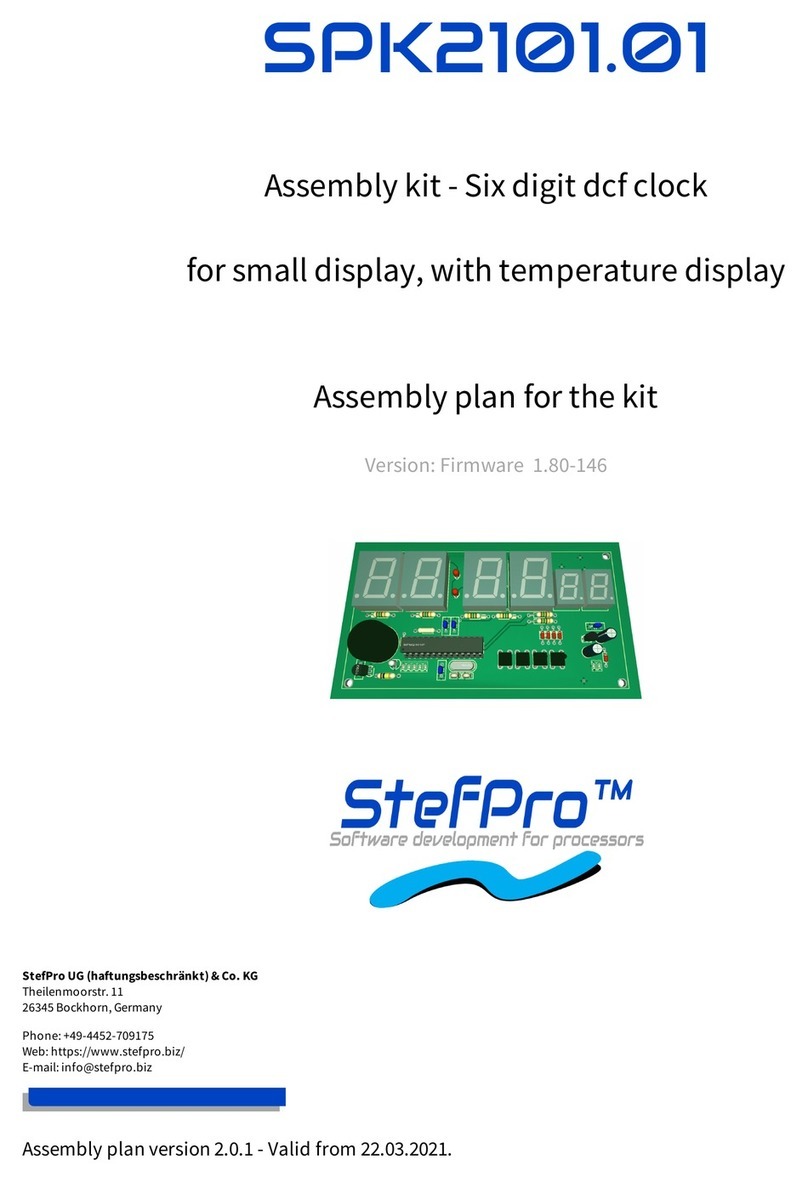
StefPro SPK2221.01 User manual

SPK2221.01
Assembly kit - Six digit dcf clock
for small weaker display, with temperature display
and extended alarm function
Assembly plan for the kit
Version: Firmware 1.80-146
StefPro UG (haftungsbeschränkt) & Co. KG
Theilenmoorstr. 11
26345 Bockhorn, Germany
Phone: +49-4452-709175
Web: https://www.stefpro.biz/
E-mail: info@stefpro.biz
Assembly plan version 2.0.1 - Valid from 22.03.2021.

2
4
5
5
5
5
6
7
8
12
12
12
14
14
14
15
15
15
16
16
16
17
17
19
19
20
20
21
21
21
23
23
23
25
25
25
25
25
26
26
26
27
27
27
28
28
28
28
28
28
29
29
29
29
29
29
30
30
30
30
30
31
31
Table of Contents
Table of Contents
Safety
Application and function description
Function description
Alarm Function
Technical data
Basic circuit
Bill of material
Basic assembly
Connectors
X-DC : DC Power input : Print plug 2 pole
X-DCF : DCF input, DCF PowerSave output: Print connector 5 pin
Properties of the components
7 segment displays
Possible displays
Calculate the series resistor for one LED
Calculate the series resistor for two LED
DCF module properties
Tested modules
Our standard color coding for DCF signals
Power supply properties
Quartz - Accuracy of the time
Buzzer to MP3 player
Properties of light sensor with Phototransistor
Temperature sensor
Method of calibration with a temperature value
Procedure for calibration with an offset value
Installation the DCF clock
Synchronize with active display
Synchronize with deactivated display
Emitted electrical disturbances by the display
Test setup
Measurement results
Button description
Overview of buttons
Button functions
General key functions
Menu
Normal
Display mode of clock
Show Temperature
Alarm
Alarm day selection
Alarm enable
Alarm time hour
Alarm time minute
Alarm snooze time
Alarm sound wait time
Alarm maximum time
Alarm exit
Brightness
Brightness menu
Brightness max
Brightness min
Brightness automatically
Brightness speed
Brightness factor
Brightness offset
Activate standby
StandBy start hour
StandBy end hour
StandBy Brightness
Exit brightness settings
StefPro - www.stefpro.biz - info@stefpro.biz - SPK2221.01 25.12.2022
Table of Contents - Page 2 of 42

31
31
31
31
32
32
32
33
33
33
33
33
33
34
34
34
34
35
35
35
35
35
35
36
37
37
37
37
38
38
38
38
39
39
39
39
40
40
40
40
40
40
41
42
42
DCF
DCF active
Receiving brightness
Hour of synchronization
Receive state display
DCF input pull up
DCF input invert
Power save pin invert
DCF sensitivity
DCF exit
Clock Settings
Set hour
Set minute
Set year
Set month
Set day
Day of week
Set time
Calibrate quartz
Exit clock settings
Info section
IC number
Firmware version
Menu end
Attachment
Bootloader handling
Start the IC/module/device in bootloader mode
Use the Firmware Upload Tool to upload an update
7 segment characters
Change log
Safety
DCF module properties
Power supply properties
Buzzer to MP3 player
Temperature sensor
Set day
Liability, warranty and copyright notice
Definitions
Liability
Safety Notes
Intended operation
Warranty
Copyrightnotice
Disposal information
Impress
StefPro - www.stefpro.biz - info@stefpro.biz - SPK2221.01 25.12.2022
Table of Contents - Page 3 of 42

Safety
Follow the manual
This assembly kit is only safe in operation if all instructions are read in this datasheet.
The assembled kit is called in the following module.
General understanding of safety
By the module there are no hazard under normal use.
Intended Use
The module is designed for driving small to middle displays.
Concealed Hazards
When handling tools such as side cutter, pliers and soldering iron there is a risk of injury. Look for a safe handling and do not touch the
hot soldering iron or just heated solder joints.
The pins of the components are very pointed and sharp! Therefore, this may cause in sores in case of incorrect handling.
The pins of the components can be pointed and sharp even after installation! Therefore, this may cause in sores in case of incorrect handling.
Spalling of parts on reverse polarity or overloading of the module.
Wear during the initial commissioning eye protection.
If the buzzer emits more than 90 dB, it may cause hearing loss over a long period of time. The circuit board is intended for installation in a
housing, thereby lowering the level of the buzzer used.
Use always passing a ESD bracelet to avoid electric charges! The module can be damaged if handling without an earthing tape and housing!
The power should come from a safe transformer (also protected transformer) or a corresponding low voltage power supply for the circuit.
Never use a higher voltage or direct mains voltage!
DANGER
following hazards may arise in case of wrong construction of the circuit and wrong handling of module:
With the direct connection to mains, it's a dangerous voltage on the module and other components, use a safety transformer!
Reverse polarity and overloading the module may cause in smoke. This smoke possibly contains toxic substances which must not be
inhaled! Ventilate the room.
Reverse polarity or overload of the module can cause a hot surface on the IC or other component in the circuit.
There is a risk of burning when touching.
And flammable materials, for example Paper, can come in fire.
Modifications of the example circuit
The successfully built device may be damaged. Therefore check as appropriate all housing part and lines for damage. This applies in particular to
parts of the directly (for example power cord and power supply) or indirectly come into contact with mains voltage.
StefPro - www.stefpro.biz - info@stefpro.biz - SPK2221.01 25.12.2022
Safety - Page 4 of 42

Application and function descriptionApplication and function description
Function description
This IC can analyze the DCF77 signal, which is received by a receiver and demodulated. Thereceived time and date can output directly to a 7-segment
displays. The clock synchronizes itself automatically once a day. The hour of the synchronization can be set in the menu.
The time is displayed according to DIN 5008, which means a leading 0 at the hour. 8 a.m. looks like 08:00:00 and 8 p.m. 20:00:00
Due to the 6-digit display, the date is not shown according to DIN 5008. The 24 December 2020 looks on the display like 24.12.20.
The DCF77 signal is a low frequency radio signal which transferred the time and date. It will besent in Frankfurt am Main, derived of the local atomic
clock and sent with the carrier frequencyof 77.5 kHz. Therefore, these watches are also known as radio clock.
The input for the DCF77 antenna can now automatically detect whether a pullup resistor isrequired and whether the input has to be inverted.
With this IC an advanced alarm clock function is implemented. In this each day can be set individually.
This IC has the new OnChip HalfMultiPlex Display technology. With this technology also small darker displays can work and the displays are
generally brighter.
This IC also has an adjustable brightness control for the display, thereby the display is easy toread during the day and at night it does not light out the
entire room.
With this IC the temperature will be displayed alternately with the time and or date.
This IC has a bootloader, which allows you to update the IC firmware.This means that you will always remain at the current state of the Firmware for
the IC, without further costs.
Alarm Function
With the extended alarm function in menu, for each day of the week, the alarm time and if the alarm is activated can be set. Furthermore, there are the
groups week and weekend to simplify the adjustment work.
In the menu the alarm and the snooze time can be set. With the adjusted snooze time the alarm waits if the alarm is not stopped at a wake-up call, but
the snooze function is activated. The maximumalarm time can be adjusted between 2 and 60 minutes.
The alarm can be activated and deactivated also outside the menu.If the wake-up call is active with S1 or S2 the alarm clock can be stopped and with
S3 or S4 the snooze function will be activated.
NOTICE
Dissembled time
Because the DCF clock daily synchronized with the current DCF time, it is possible that in worst cases, an incorrect time is read and therefore the
wake-up call comes at a wrong time! Therefore, the time synchronization should eventually be placed in a time of day where it is possible to check
the correct time before sleeping, if the alarm function is used.
Note: At this IC, there are no simple alarm function as described in the data sheet SPM21xx.
Technical data
Operating voltage: 9 - 12 volts DC
Current: 200mA
Power: approximately 1.8 W (at 9 volts)
Volume level of the buzzer: approx. 85 to 90 DB
Accuracy of the timer: better uncalibrated 99.9 %; calibrated better 99.999 %
Temperature accuracy:
Worst inaccuracy: ±2.5 °C
Typical: ±1 °C
Calibrated: <±1 °C
The values apply when using the LM35, when calibrated, the value can also be reached for other sensors.
StefPro - www.stefpro.biz - info@stefpro.biz - SPK2221.01 25.12.2022
Application and function description - Function description Page 5 of 42

Basic circuitBasic circuit
Figure 1: Basic circuit of SPK2221.01 part 1
Figure 2: Basic circuit of SPK2221.01 part 2
StefPro - www.stefpro.biz - info@stefpro.biz - SPK2221.01 25.12.2022
Basic circuit - Function description Page 6 of 42

Bill of material
Pos Quantity Name Value Package
Scope of delivery
1 6 D3,D6,D5,D7,D8,D10 1N4148 D3
2 6 R1,R3,R4,R5,R6,R8 4k7 1/4 0207
3 8 R7,R10,R11,R12,R13,R14,R15,R16 100 1/4 0207
4 1 R9 100k 1/4 0207
5 1 R17 47k 1/4 0207
6 1 R18 1k 1/4 0207
7 6 R1,R3,R4,R5,R6,R8 4k7 1/4 0207
8 1 L1 10µH R-1016
9 4 C3,C4,C8,C11 100n C2
10 2 C9,C10 Kerko 27p C1
11 1 C12 1n C2
12 1 Q2 8MHz HC49/U
13 1 IC3 78L05 TO92
14 1 IC4 IC-Sockel 28 Small DIL28/S
15 1 T1 LM35DZ TO92
16 1 T2 BPW 42 FOTO_5MM
17 6 T3,T4,T5,T6,T7,T8 BC327-40 TO92
18 1 T9 BC547A TO92
19 1 S5 Buzzer TDB 05 D18R7,62
20 1 C1 100µ 16 ELKO1
21 1 C2 10µ 16 ELKO1
22 4 S1,S2,S3,S4 PHAP3301D KURZHUBTASTER_6X6
23 1 IC4 SPM2121P or SPM2221P DIL28/S
24 1 SPP2200 PCB
To order separately
25 2 D1,D2 LED 3mm LED_3MM
26 4 STD_Z1,STD_E2,MIN_Z3,MIN_E4 SA08 S_08
27 2 SEK_Z5,SEK_E6 SA56 S_56
28 1 X-DC1
29 1 X-DCF1
StefPro - www.stefpro.biz - info@stefpro.biz - SPK2221.01 25.12.2022
Basic circuit - Bill of material Page 7 of 42

Basic assemblyBasic assembly
The basics of electronics and PCB assembly can be found in the document:"Grundlagen der Elektrotechnik, Grundlagen des bestückens von
Platinen".Unfortunately currently only available in German.
Figure 3: Basic assembly of SPK2221.01
Assembly plan with names
Figure 4: Basic assembly of SPK2221.01 1
Assembly plan with values
StefPro - www.stefpro.biz - info@stefpro.biz - SPK2221.01 25.12.2022
Basic assembly - Bill of material Page 8 of 42

Figure 5: Basic assembly of SPK2221.01 step 1
First, solder flat components, such as resistors, diodes and coils. Attention: the coil L1 is shown wrong, this is [brown, black, black, silver].
Figure 6: Basic assembly of SPK2221.01 step 2
Now you can solder ceramic capacitors and the quartz.
StefPro - www.stefpro.biz - info@stefpro.biz - SPK2221.01 25.12.2022
Basic assembly - Bill of material Page 9 of 42

Figure 7: Basic assembly of SPK2221.01 step 3
Now comes the IC socket for the SPM2121P. The IC SPM2121P can also be soldered directly, but should not.
Figure 8: Basic assembly of SPK2221.01 step 4
Now it's time for the transisitors and TO92 IC's, be sure to leave a little space to the PCB. This also applies to the BPW42. The buzzer can
now also be soldered.
StefPro - www.stefpro.biz - info@stefpro.biz - SPK2221.01 25.12.2022
Basic assembly - Bill of material Page 10 of 42

Figure 9: Basic assembly of SPK2221.01 step 5
The buttons and Elko's are a bit higher and are therefore now their turn.
Figure 10: Basic assembly of SPK2221.01 step 6
Finally, the LEDs and 7 segment displays (these are to be ordered separately), these are to be soldered directly onto the PCB.
StefPro - www.stefpro.biz - info@stefpro.biz - SPK2221.01 25.12.2022
Basic assembly - Bill of material Page 11 of 42

Figure 11: Basic assembly of SPK2221.01 step 7
The finally assembled pcb, only the wires for the supply voltage and the DCF receiver are missing.
Connectors
Figure 12:Connector description for module SPP2200.0
Here, the leads are soldered directly to the pins on the circuit board. You can solder them from the front or the back.
DANGER
Make sure that you have connected all signals correctly. There is no overload and polarity protection!
X-DC : DC Power input : Print plug 2 pole
Pin Name Direction Function Maximum
1 GND Power
2 V+ Power Power supply input of the
module
9 - 12 volts DC, 200mA
X-DCF : DCF input, DCF PowerSave output: Print connector 5 pin
Pin Name Direction Function Maximum
1 GND Power
StefPro - www.stefpro.biz - info@stefpro.biz - SPK2221.01 25.12.2022
Basic assembly - Connectors Page 12 of 42

2 N.C. Do not connect VCC
3 DCF in Digital input DCF signal input VCC
4 DCF ps Digital Output DCF PowerSave output VCC
5 VCC Power 5 volts DC, 30mA
Never solder the DCF module directly onto the circuit board, even if the ELV module suggests it. Please connect this with some stranded wire to allow a
certain distance to the display.
StefPro - www.stefpro.biz - info@stefpro.biz - SPK2221.01 25.12.2022
Basic assembly - Connectors Page 13 of 42

Properties of the componentsProperties of the components
7 segment displays
The seven-segment display LD1 must have a common anode. The anode is driven by a transistor which must withstand at least 100 mA on the CE track.
Via R1, the brightness of the LEDs of each display can be adjusted in limits.It should be noted that with direct control by SPK2221.01 the maximum
current in SEG_A SEG_DP is 20 mA. R2 to R9 are the LED resistors, these are for example a 6 digit display used just once. The resistors are connected to
the IC.The other displays are to be wired in the same way.
Possible displays
For big displays SA08-11SRWA in red, SA08-11YWA in yellow, SA08-11PBWA in blue and for small displays SA52-11SRWA in red, SA52-11YWA in yellow,
SA52-11PBWA in blue by Kingbright. Others on request.
Figure 15: SA08-11SRWA left without and right with contrast pane with back light.
Figure 16: SA08-11SRWA left without and right with contrast pane without back light.
Below with and above without back light.
Because the displays are half multiplexed (only four LEDs are lights at the same time for a maximum of 6 microseconds) to minimize component count
and power consumption, not all 7-segment displays are usable.
Also note, that the displays which can work with 10 mA constant current, not implicitly work with 10 mA pulsed current.All displays have been limited
with a 100 ohm resistor.
The brightness of the display is designed for the brightness conditions in a living room or laboratory. Since the circuit is optimized for minimum
components and power consumption, the readability is limited with direct irradiation by spotlight or sunlight without a contrast panel very limited
and with better.
StefPro - www.stefpro.biz - info@stefpro.biz - SPK2221.01 25.12.2022
Properties of the components - 7 segment displays Page 14 of 42

It is recommended to place a contrast panel in front of the display, see figure 16 and 15.
Note: The menu is always displayed with 100% brightness.
Calculate the series resistor for one LED
UDS ≈ 0
ILED < 35 mA
Calculate the series resistor for two LED
UDS ≈ 0
ILED < 35 mA
DCF module properties
The module has to be able to work with an operating voltage of 5V (some modules have an operating voltage range of 1.2 to 15 volts, these are
also usable)
The output has to be able to drive a CMOS input with a input impedance of 10kO
StefPro - www.stefpro.biz - info@stefpro.biz - SPK2221.01 25.12.2022
Properties of the components - 7 segment displays Page 15 of 42

For DCF modules with open collector (open collector) or open drain output the input detected automatically by default whether a pull-up
resistor is required. In menu a pull-up resistor can be connected or disconnected permanently.
Polarity of the output:
The output has to be non inverting, the high state has to be 100ms or 200ms
The output has to be inverting, the low state has to be 100ms or 200ms
The receiving LED should at good reception signal flash every second for 100 ms and 200 ms. Does the receiving LED goes off every second
for 100 ms and 200 ms, then the polarity is wrong. Unfortunately, you then connected a wrong module, this can't be analyzed with the
microcontroller.
Whether the output is non inverting or inverting, is detected automatically by default or can be set in the menu.
The receiving LED should at good reception signal flash every second for 100 ms and 200 ms. Does the receiving LED goes off every second
for 100 ms and 200 ms, then the polarity is wrong. To correct this, you has to be invert the setting for the inverting DCF input pin in the
menu. (Instead of on → off → on or off)
The DCF module can have a power on / off pin. Then the DCF module is automatically switched off when the DCF signals from the
microcontroller are not analyzed. In the menu can be set if the DCF module is with low or high on.
Tested modules
M oduleM odule GNDGND VC CVC C DC F inputDCF input P ow er Sa veP ow er Sa ve
out putout put
CommentComment
Conrad DCF Modul 1 (GND) 2 (Betriebs...) 3 (DCF Ausgang) -
ELV DCF Modul 3 (Masse) 1 (+ UB) 2 (Signal-Ausgang) -
Pollin DCF Modul GND VCC DATA PON Caution An additional circuit is required for an operating voltage of more
than 3.3V!
Our standard color coding for DCF signals
GND: black
VCC: rot
DCF input: green
PowerSave output: white ( is not supported by each DCF receive module )
Connect the DCF module with approx. 10 cm wire, it is best to select the colors as in the table above, so that this can be mounted at some distance
from the display.
WARNING
Please check the pin assignments! It is not in our hands whether the manufacturers of the DCF receive modules change the pin assignments at a
later date.
Power supply properties
Since the clock is usually to be operated on a 230 volt power supply, a power supply unit is required. This can be a normal transformer power supply
or a switching power supply.
Transformer power supply:
Pro:
Cheap
Little interference for DCF reception
Contra:
Heavy
Depending on the power is it big
Poor efficiency
Even if the circuit requires little power, some power may be needed
Higher electricity costs
Switching Power Supply:
Pro:
Light
Small
Good efficiency is possible
Standby possible with very low power requirements
Lower electricity costs than with the transformer power supply
Contra:
Larger interference for DCF reception
Usually a little more expensive
Switching power supplies should be preferred, unfortunately they have the disadvantage that many can interfere with the DCF reception and the DCF
clock is not synchronized.Switching power supplies with a PE feedthrough (PE is connected to ground) often have better interference behavior, but
StefPro - www.stefpro.biz - info@stefpro.biz - SPK2221.01 25.12.2022
Properties of the components - Power supply properties Page 16 of 42

this cannot be generalized.The switching power supplies offered in our shop have been tested and only minimally interfere with DCF reception.
WARNING
Use only a power supply unit with electrical isolation!
Quartz - Accuracy of the time
The quartz, microcontroller, quartz capacitor combination decisively determine the accuracy of the clock. Since the kit is delivered unassembled,
prior coordination is not possible and only uncalibrated accuracy is ensured.
The supplied accuracy is completely sufficient for normal use if the clock is synchronized daily with the DCF time.
The accuracy can be measured on the TB pin, which can be found in the pin assignment in the corresponding data sheet for the IC. If the clock is
inaccurate, first check the soldering points of the quartz, the quartz capacitors and the controller. These solder points must be correctly soldered and
dirt such as Flux should be removed.
You can carry out a calibration yourself with the appropriate measuring equipment or you can order it from us with cost. Check the items in our shop.
To carry out the calibration, measure on pin TB with a multimeter, which frequency or period measurement can or with a frequency meter the output
frequency. This should be as accurate as possible at 1 kHz or 1ms (for period measurement). A long gate time (duration of the frequency
measurement) is advantageous because the interrupts create a little jitter (slight variation in the frequency). The calibration can be done digitally in
firmware in somewhat rough steps in the menu "Calibrate quartz" or with a trim capacitor (this is not listed in a kit or parts list) in very fine steps. The
best result is achieved by a trimming capacitor. However, since these are rarely produced, they are expensive and the increase of accuracy is minimal.
Furthermore, for trimming capacitors you need a good tactile adjustment tool, a "normal" screwdriver usually does not work.
Figure 17: Calibrate quartz
NOTICE
Of course, the measuring device must have a corresponding accuracy.
Buzzer to MP3 player
If an MP3 player is to be used instead of a self-exciting buzzer, a small circuit must bridge the signal off time.
This is possible with this very simple circuit, with a NE555, build-up as a retriggerable mono-flop.
Furthermore, there is a small power supply for the MP3 module, because most of the imported modules requires a voltage supply of 5 volts.The
current is still acceptable with a connected 4 Ohm loudspeaker for a 7805 with heat sink and a current of 200 to 500 mA, since the alarm shouldnot
play for more than 30 min. However, it is also possible to use a PIN compatible DCDC converter by different manufacturers.
StefPro - www.stefpro.biz - info@stefpro.biz - SPK2221.01 25.12.2022
Properties of the components - Quartz - Accuracy of the time Page 17 of 42

Combination R1 and C3 gives a mono time of approx. 2 min.
Colors of thin wires:
red: plus supply voltage (<= + 12 Volt)
black: minus supply voltage
white: Buzzer signal from the IC SPK2221.01
orange: plus MP3 Player Module (+5 Volt)
green: minus MP3 Player Module
StefPro - www.stefpro.biz - info@stefpro.biz - SPK2221.01 25.12.2022
Properties of the components - Quartz - Accuracy of the time Page 18 of 42

Colors of the signals:
yellow: Trigger signal
light blue: MP3 Player Power Supply
dark blue: Output from the MP3 Player
Properties of light sensor with Phototransistor
The light sensor is used to control the brightness of the display.As light sensors many phototransistors are suitable, in the example circuit a BPW42 is
used.If another phototransistor is used, may you need to change the value of the pull-up resistor R1. The menu allows to adjust the calculation factor,
offset and the control speed.If the sensor is mounted behind a contrast panel, it must be taken to ensure that the wavelength of the phototransistor
can passed through the contrast screen.
In the case of the BPW42 and similar photo transistors in the LED diode housing, the incidence of light must take place as follows in order to achieve
the best result:
NOTICE
When using a different phototransistor or a different photodiode, it may be necessary to adapt R1 (top picture) and the settings in the menu!
Temperature sensor
The temperature sensor is used to display the temperature and it must be an analog sensor with 10mV / 1°C. This is to be connected to the
temperature sensor input (TempSen).
From version 1.79-144 the temperature sensor can be calibrated and also display negative temperatures.The calibration is done with one decimal
place, but the display is always an integer.
When installing the temperature sensor, make sure that it does not receive any foreign heating, installation directly on the circuit board can make a
difference of several ° C (Kelvin) under certain circumstances!
StefPro - www.stefpro.biz - info@stefpro.biz - SPK2221.01 25.12.2022
Properties of the components - Quartz - Accuracy of the time Page 19 of 42

R1 is optional for the detection of whether a sensor is connected or not; this is not necessary with permanent wiring.
Method of calibration with a temperature value
You can carry out a calibration with a temperature value yourself with a suitable temperature measuring device.
1. Use a temperature measuring device that is as accurate as possible to measure the temperature that the connected temperature sensor is
exposed to; ideally, both sensors are thermally coupled.
2. Select Show temperature in the menu and press the + button for longer than a second, the currently measured temperature is displayed.
3. Set the temperature from the precise temperature measuring device and wait briefly until the display jumps back.
4. The correct temperature should now appear on the display. If this is not the case, repeat the process.
Procedure for calibration with an offset value
The calibration with offset value is intended if you buy a sensor with a previously measured offset value.
1. Select Display temperature in the menu and press the button for longer than one second, the current offset value is displayed.
2. Set the supplied offset value and wait briefly until the display jumps back.
3. The correct temperature should now appear on the display. If this is not the case, please contact us.
The calibration only refers to the offset, the linearity cannot be changed!
StefPro - www.stefpro.biz - info@stefpro.biz - SPK2221.01 25.12.2022
Properties of the components - Quartz - Accuracy of the time Page 20 of 42
Table of contents
Other StefPro Microcontroller manuals
Popular Microcontroller manuals by other brands
mikroElektronika
mikroElektronika Mikromedia MIKROE-608 manual

decaWave
decaWave MDEK1001 quick start guide
Nuvoton
Nuvoton NuMicro M480 Series quick start guide
GigaDevice Semiconductor
GigaDevice Semiconductor GD32F10 Series user manual
Texas Instruments
Texas Instruments CC2510 Quick start instructions

Holtek
Holtek HT32F52342 user manual
