8CrossoverElettronico.
Gli amplificatori “QMOS II” 150.1x e 240
.1x hanno internamente un crossover
elettronico passa-basso e un crossover
elettronico passa-alto escludibile per la
sezionedi uscita(OUTPUT)(HIGH)(fig.a).
Questo permette di ottimizzare la resa
dell’eventuale amplificatore dedicato al
resto della gamma audio per esempio nel
caso si voglia limitare lo stress meccanico
dei woofer con possibile rottura del
componentedovutoa sollecitazioni elevate,
sipuòutilizzareil filtro passa-alto come filtro
subsonico selezionando una frequenza di
taglio molto bassa (es. 22 Hz). Tutte le
frequenze inferiori al valore selezionato
vengono filtrate e il woofer inizia a
riprodurre dalla frequenza impostata che
corrisponde alla sua migliore condizione di
lavoro. Per attivare il crossover elettronico
agire sul comando (FILTER) e portarlo sulla
posizione(ON)(fig.a).Quandoilcomandoè
in posizione (OFF) la banda passante
dell’uscita (HIGH) è a gamma intera. La
pendenza del taglio del crossover interno
degli amplificatori “QMOS II” è di 12
dB/OCT, le frequenze di taglio viene
impostata dal valore dei moduli AQXM2,
inseriti nelle fessure HIGH e LOW,
posizionate sotto l’amplificatore (fig. 9b).
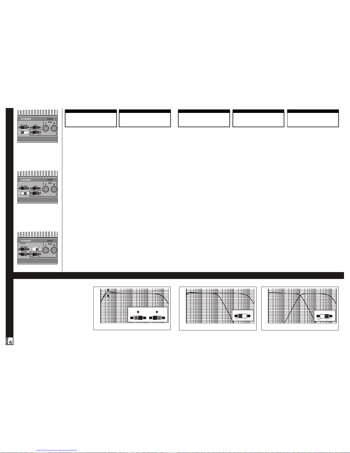
Nel caso dei modelli 150.1x e 240 .1 x la
pendenza del filtro passa basso può essere
settato a 12 dB/OCT o a 24 dB/OCT agendo
sul selettore (SLOPE-dB LOW) (fig. b) ,
questa ulteriore possibilità permette di
regolare finemente la risposta del/dei
Subwoofer, un ulteriore chiarimento delle
funzioni di crossover è dato dai grafici delle
pagine14 -15(fig.11e11f).
9Modulo AQXM2.
Le frequenze di taglio del crossover
elettronico sono selezionabili con la
massima precisione attraverso l’inserimento
del modulo AQXM2 opzionale (fig. a)
disponibile presso i rivenditori nei
valorielencati.
Il moduli AQXM2 vanno inseriti nelle
piccole aperture poste sul pannello inferiore
dell’amplificatore (fig b).Il filtro passa alto è
attivato senza inserire il modulo AQXM2
nell’apposita sede. In questo caso si ottiene
unfiltro subsonicocontaglioa22Hz..
steg
8ElectronicCrossover .
The “QMOS II” 150.1x and 240 .1x
amplifiers have an internal low-pass
electronic crossover and arule out internal
high-pass electronic crossover dedicated to
the output line (OUTPUT) (HIGH) (fig. a).
This allows optimize overall efficiency of the
eventually amplifier dedicated at the rest of
audio band, for example in case of wanting
tolimitmechanicalstress ofthewooferswith
possible breakage of the component due to
high stress, the high-pass filter may be used
as subsonic filter by selecting a very low cut-
off frequency (e.g. 22 Hz). All frequencies
lowerthan thevalueselectedarefilteredand
the woofer starts reproducing from the set
frequency which corresponds to its best
operating condition. To activate the
electronic crossover, act on the (FILTER)
controlandsetittothe(ON)position(fig.a).
When the control is in the (OFF) position,
the pass-band of the amplifier is full range.
The cut-off slope of the internal crossover of
the“QMOS II”amplifiersis12dB/OCT, the
cut-off frequencies are selected by the value
of AQXM2 modules, inserted in the small
openings HIGH and LOW, located on the
lowerpanel oftheamplifier(fig. 9b).
In particulary on the “QMOS II” 150.1x
and 240 .1x amplifiers the low pass filter
cut-offslope canbeswitchedin12dB/OCT
or 24 dB/OCT by the (SLOPE-dB LOW)
selector(fig.b), thiscapabilitymakeyouable
to trim in fine mode the subwoofer/s
response, other explanations by the
grahphicson pages14-15 (fig.11e11f).
9AQXM2Module.
The cut-off frequencies of the electronic
crossover are selectable with maximum
precision through insertion of the optional
AQXM2 module (fig. a) available at
dealersin thevaluesindicated.
The AQXM2 module is inserted in the small
opening located on the lower panel of the
amplifier (fig. b).The high-pass filter is
activated without inserting the AQXM2
moduleinitshousing.Inthiscaseasubsonic
filteris obtainedwithcut-offat22Hz.
steg
8CrossoverElectronique
Lesamplificateurs "QMOS II"150.1xet240
.1x sont équipés à l'intérieur d'un crossover
électronique passe-bas et d'un crossover
électroniquepasse-haut pouvant être exclus
parla sectiondesortie(OUTPUT)(HIGH)
(fig. a).Cela permet d'optimiser le
rendement de l'éventuel amplificateur
réservé au reste de la gamme audio par
exemple si l'on veut limiter le stress
mécanique des woofers, avec risque de
rupture possible du composant à cause des
sollicitations importantes, on peut utiliser le
filtrepasse-haut commefiltresubsoniqueen
sélectionnant une fréquence de coupe très
basse (ex. 22 Hz). Toutes les fréquences
inférieures à la valeur sélectionnée sont
filtrées et le woofer commence à reproduire
delafréquencesélectionnéequicorrespond
à sa meilleure condition de service. Pour
activer le crossover électronique, agir sur la
commande (FILTER) et la placer sur la
position (ON)(fig. a). Lorsque la commande
estsurla position(OFF)labandepassante de
la sortie (HIGH) est à gamme entière. La
pentedecoupedu crossover à l'intérieurdes
amplificateurs “QMOS II" est de 12
dB/OCT, les fréquences de coupe sont
programmées par la valeur des modules
AQXM2, installés dans les fentes HIGH et
LOW, positionnées sous l'amplificateur (fig.
9b). Dans le cas des modèles 150.1x et 240
.1 x la pente du filtre passe-bas peut être
réglée à 12 dB/OCT ou à 24 dB/OCT en
agissant sur le sélecteur (SLOPE-dB LOW)
(fig. b) , cette autre possibilité permet de
régler avec précision la réponse du/des
Subwoofer. Un autre éclaircissement, des
fonctions de crossover, est fourni par les
graphiquesaux pages14-15(fig.11e11f).
9ModuleAQXM2.
Les fréquences de coupe du crossover
électronique sont sélectionnables avec la
plusgrandeprécisiongrâceàl'installationdu
module AQXM2 en option (fig. a) et
disponible chez les revendeurs dans
lesvaleurs énumérées.
Le module AQXM2 doit être installé dans la
petite ouverture placée sur le panneau
inférieurde l'amplificateur(fig.b).
steg
8ElektronischerCrossover.
Die Verstärker “QMOS II" 150.1x und 240
.1x sind inwendig mit einem elektronischen
Tiefpass-Crossover und mit einem
elektronischen Hochpass-Crossover, der für
dieAusgangsbereich (OUTPUT)(HIGH)
(Abb. a) ausgeschlossen werden kann,
ausgestattet. Dadurch wird es ermöglicht,
die Leistung des eventuell für den Rest des
Audiobandes vorgesehenen Verstärkers zu
optimieren. Möchte man zum Beispiel die
mechanischeBelastungderWoofermit dem
möglichen,durch erhöhte
Beanspruchungen verursachten Bruch der
Komponente verringern, kann der
Hochpassfilter als subsonischer Filter
verwendet werden, indem eine sehr
niedrige Schnittfrequenz gewählt wird (z.B.
22 Hz). Alle unter dem ausgewählten Wert
liegenden Frequenzen werden gefiltert und
der Woofer beginnt mit der Wiedergabe ab
dereingestelltenFrequenz, dieseinerbesten
Arbeitsbedingung entspricht. Zur
Aktivierung des Elektronik-Crossover ist das
Steuerelement (FILTER) zu betätigen und in
die Stellung (ON) (Abb. a) zu bringen. Wenn
sich das Steuerelement in der Position (OFF)
befindet, ist der Durchlassbereich des
Ausgangs (HIGH) auf die volle Bandbreite
eingestellt. Das Schnittgefälle des Crossover
im Inneren der Verstärker “QMOS II"
beträgt 12 dB/OCT. Die Schnittfrequenz
wird durch den Wert der AQXM2-Module
eingestellt, die in den unter dem Verstärker
liegenden Schlitzen HIGH und LOW,
eingebaut sind (Abb. 9b). Bei den Modellen
150.1x und 240 .1 x kann das Gefälle des
Tiefpassfilters durch Betätigung des
Wählschalters(SLOPE-dBLOW)(Abb.b) auf
12 dB/OCT oder auf 24 dB/OCT eingestellt
werden. Diese weitere Möglichkeit erlaubt
die Feineinstellung der Reaktion des/der
Subwoofer. Eine weitere Erklärung der
Crossover-Funktionen wird von den
Schaubildern auf den Seiten 14 -15 (Abb.
11e11f) gegeben.
9ModulAQXM2.
Die Schnittfrequenzen des elektronischen
Crossovers mit dem Zusatzmodul AQXM2
(Abb. a), das bei de -Händlern
erhältlichist, mit der äußerstenPräzisionauf
dieaufgeführten Werteeingestelltwerden.
Das Modul AQXM2 wird in die kleine
Öffnung auf der Unterseite des Verstärkers
eingesteckt(fig b).
steg
8Filtroelectrónico (crossover)
Los amplificadores “QMOS II" 150.1x y
240.1x tienen incorporados un crossover
electrónico de paso bajo y uno de paso alto
posible de desactivar para la sección de
salida(OUTPUT/HIGH)
(fig. a). Ello permite optimizar el
rendimiento del eventual amplificador
dedicado al resto de la gama audio. Por
ejemplo, si se desea limitar el esfuerzo
mecánico de los woofer y la posible rotura
del componente debido a grandes
requerimientos,esposibleutilizarel filtro de
paso alto como filtro subsónico,
seleccionando una frecuencia de corte
sumamentebaja(p.ej.22Hz).Deesemodo,
seránfiltradas todaslasfrecuencias inferiores
alvalor seleccionado y el woofer comenzará
a reproducir desde la frecuencia
establecida, que corresponde a su mejor
condición de trabajo. Para activar el
crossover electrónico, llevar el mando
FILTER a la posición ON (fig. a). Cuando el
mando está en posición OFF, la banda libre
de la salida (HIGH) es de gama entera. La
inclinación del corte del crossover
incorporado de los amplificadores “QMOS
III" es de 12 dB/OCT, las frecuencias de
corte son establecidas por el valor de los
módulos AQXM2, introducidos en las
ranuras HIGH y LOW situadas debajo del
amplificador(fig.9b). Enlosmodelos150.1x
y 240.1 x, la inclinación del filtro de paso
bajo puede ser establecida a 12 dB/OCT o a
24 dB/OCT mediante el selector (SLOPE-dB
LOW) (fig. b). Esta posibilidad permite
regular con precisión la respuesta del/de los
Subwoofer (para más detalles sobre las
funcionesdecrossover,verlosgráficos de las
páginas14 -15,fig.11ey 11f).
9Módulo AQXM2.
Lasfrecuenciasde cortedelfiltroelectrónico
se seleccionan con suma precisión
aplicando el módulo AQXM2 opcional (fig.
a),disponibleenlosrevendedores en
losvalores indicados.
El módulo AQXM2 se introduce en la
pequeña abertura situada en el panel
inferiordel amplificador(fig.b).
steg
9a
- Hz -
25,30,33,35,38,40,45,
50,55,60,65,70,75,80,85,90,95,100,
110,120,130,150,180,200,250,300,350,
400,450,500,600,700,800,900,1000,
1100,1200,1300,1400,1500,1800,2000,
2500,3000,3500,4000,4500,5000,
5500,6000,6500,7000,7500,8000,8500.
9b
AQXMAQXM
8b
8a
AQXM2 CUT FREQ. MODULES BOTTOMSIDE
pag. 13
ATTENTION VORSICHT PRECAUCIONCAUTIONATTENZIONE PARA EVITAR EL COMIENZO DE LAS
PROTECCIONES O DEL DAÑO DE LOS
ALTAVOCES, LOS SELECTORES DEBEN SER
FIJADOSSOLAMENTESIELAMPLIFICADOR SE DA
VUELTA APAGADO (NINGÚN VOLTAJE EN EL
CONECTORDEL"REM").
UM DEN ANFANG DER SCHUTZE ODER DER
LAUTSPRECHERCBESCHADIGUNG ZU
VERMEIDEN, MÜSSEN DIE SELEKTOREN
EINGESTELLT WERDEN, NUR WENN
VERSTÄRKER WEG GEDREHT WIRD (KEINE
SPANNUNGAUF"REM"STECKER).
AFIN D'CÉVITER LE DÉBUT DES PROTECTIONS OU
DES DOMMAGES DE HAUT-PARLEURS, LES
SÉLECTEURS DOIVENT ÊTRE PLACÉS
SEULEMENT SI L'AMPLIFICATEUR EST ARRÊTÉ
(AUCUNETENSIONSURLECONNECTEURD'C"
REM").
IN ORDER TO AVOID THE START OF THE
PROTECTIONS OR SPEAKERS DAMAGE, THE
SWITCHESMUST BE SET IFAMPLIFIER ISTURNED
OFFONLY(NOVOLTAGEON"REM"CONNECTOR).
ONDE EVITARE L'INTERVENTO DELLE
PROTEZIONI O DANNI AGLI ALTOPARLANTI,
SETTARE I SELETTORI SOLALMENTE AD
AMPLIFICATORE SPENTO (NESSUNA TENSIONE
SULMORSETTO"REM").