- 12 - - 13 -- 12 -
tection zone is noticed by the sensor as a change
in echo. A microprocessor then issues the switch
command "switch light ON". Detection is possible
through doors, panes of glass or thin walls.
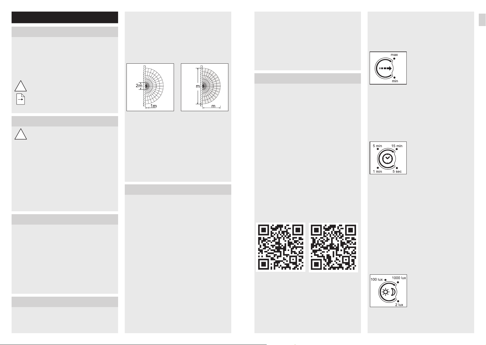
Detection zones for wall mounting:
1) Minimum reach (1m)
2) Maximum reach (5m)
1)
5
2)
14
Note:
The high-frequency output of the iHF sensor is
is approx. 1mW – 1000times less than the transmis-
sion power of a mobile phone or microwave oven.
Note:
The sensor is suitable for switching light on auto-
matically. Note: weather conditions may aect the
way the sensor works. Strong gusts of wind, snow,
rain or hail may cause the light to come on when it
is not wanted.
5. Electrical connection
To achieve the stated reach of 5m, the light should
be mounted at a height of approx. 2m.
Connecting the mains power supply lead
(see diagram j)
a= without Bluetooth
b= with Bluetooth – individual connection
c= with Bluetooth – interconnected
The supply lead is a three-core cable:
L= phase conductor (usually black,
brown or grey)
N= neutral conductor (usually blue)
PE = protective-earth conductor (green/yellow)
If you are in any doubt, identify the conductors
using a voltage tester; then disconnect
from the power supply again. Phase (L) and neutral
conductor (N) are connected to the terminal block.
Important:
Incorrectly wired connections will produce a short
circuit later on in the product or your fuse box. In
this case, you must identify the individual conduc-
tors once again and reconnect them.
GB
1. About this document
Please read carefully and keep in a safe place.
• Under copyright. Reproduction either in whole or
in part only with our consent.
• Subject to change in the interest of technical
progress.
Symbols
Hazard warning!
...
Reference to other information in the
document.
2. General safety precautions
!Disconnect the power supply before
attempting any work on the unit.
• During installation, the electric power cable being
connected must not be live being connected
must not be live. Therefore, switch o the power
first and use a voltage tester to make sure the
wiring is o-circuit.
• Installing the sensor-switched light involves work
on the mains voltage supply. This work must
therefore be carried out professionally in accord-
ance with national wiring regulations and electri-
cal operating conditions. (e.g. DE: VDE 0100,
AT: ÖVE / ÖNORM E8001-1, CH: SEV 1000)
3. L825LEDiHF Connect
aWall mount
bLight enclosure
cSpacer for surface-mounted installation
dLight diuser
eReach setting
fTime setting
gTwilight setting
hProgramme setting
iManual override
IConcealed installation
II Surface-mounted installation
4. Principle
Sensor-switched light with an active motion detec-
tor. The integrated iHF sensor emits high-frequency
electromagnetic waves (5.8GHz) and receives their
echo. Any movement by persons in the light's de-
Note:
The light source of this luminaire cannot be
replaced. If the light source needs to be replaced
(e.g. at the end of its service life), the complete
luminaire must be replaced.
A mains power switch for turning the unit ON and
OFF may of course be installed in the mains supply
lead.
6. Functions
The sensor-switched light can be put into service
after mounting the enclosure aand connecting to
the mains power supply. When putting the light into
operation manually at the light switch, it will switch
OFF after 10seconds for the calibration phase and
is then activated for sensor mode.
It is not necessary to operate the light switch a
second time.
Functions can be set via Smart Remote app or
control dial.
Note:
The settings last selected on the control will be
used.
Smart Remote app
To configure the light via smartphone or tablet, you
must download the STEINEL Smart Remote app
from your app store. You will need a Bluetooth-ca-
pable smartphone or tablet.
QR codes
Android iOS
Additional functions only via the Smart Remote
app:
– Main light- / basic light level adjustable
– Extended reach adjustment
– Group interconnection
– Twilight setting by teach-in
Reach setting (sensitivity ) e
Factory setting: 5m
Reach is the term used to describe the diameter of
the more or less circular detection zone produced
on the ground after mounting the sensor-switched
light at a height of 2.5m.
- Potentiometer set to
maximum = max. reach 5 m
- Potentiometer set to minimum
= min. reach 1m
- Potentiometer set to "•" =
sensor o
Motion detection and all other sensor functions are
completely deactivated (sensor o). In this setting,
the light can be used as a normal light and turned
ON and OFF at the light switch.
Time setting (switch-OFF delay) f
Factory setting: 5s
The light's ON time can be set to any period from
approx. 5s to a maximum of 15min.
Adjustment control set to:
15min = maximum time
(15min )
5sec = minimum time (5s )
We recommend selecting the
shortest time (5sec) for setting
the detection zone.
Any movement detected before this time elapses
will restart the timer. The shortest time setting is
recommended when adjusting the detection zone
and performing the functional test.
Note:
After the light switches OFF, it takes approx. 1sec-
ond before it is able to start detecting movement
again. The light will only switch ON in response to
movement once this period has elapsed.
Twilight setting (response threshold) g
Factory setting: 1000lux
The chosen response threshold can be infinitely
varied from approx. 2to 1000lux.
Adjustment control set to:
1000lux = approx. 1000lux
2lux = night-time operation
approx. 2lux
To adjust the detection zone in daylight, the control
dial must be set to 1000lux.
GB