STEINEL L 220 LED User manual

Best - Snab
ул.1812 года, дом 12
121127 Москва · Россия
Tel: +7 (495) 280-35-53
[email protected] · www.steinel.su
RUS
SAET-94 S.L.
C/ Trepadella, n° 10
Pol. Ind. Castellbisbal Sud
E-08755 Castellbisbal (Barcelona)
Tel.: + 34/93/772 28 49
Fax: +34/93/772 01 80
Pronodis - Soluções Tecnológicas, Lda.
Zona Industrial Vila Verde Sul, Rua D, n.º 11
P-3770-305 Oliveira do Bairro
Tel.: +351 234 484 031
Fax: +351 234 484 033
[email protected] · www.pronodis.pt
Roliba A/S
Hvidkærvej 52
DK-5250 Odense SV
Tel.: +45 6593 0357
Fax: +45 6593 2757
www.roliba.dk
Oy Hedtec Ab
Lauttasaarentie 50
FI-00200 Helsinki
Tel.: +358/207 638 000
Fax: +358/9/673 813
[email protected] · www.hedtec.fi/valaistus
Vilan AS
Olaf Helsetsvei 8
N-0694 Oslo
Tel.: +47/22 72 5000
www.vilan.no
ELNAS s.r.o.
Oblekovice 394
CZ-671 81 Znojmo
Tel.: +4 20/5 15/2201 26
Fax: +4 20/5 15/2443 47
[email protected] · www.elnas.cz
CZ
E
P
S
DK
FI
N
PANOS Lingonis + Sons O. E.
Aristofanous 8 Str.
GR-10554 Athens
Tel.: + 30/210/3 2120 21
Fax: +30/210/3 21 8630
GR
SAOS Teknoloji Elektrik Sanayi ve
Ticaret Limited Şirketi
Halil Rıfat Paşa mahallesi
Yüzerhavuz Sokak
PERPA Ticaret Merkezi A Blok Kat 5 No.313
Şişli / İSTANBUL
Tel.: +90 212 220 09 20
Fax: +90 212 220 09 21
www.saosteknoloji.com.tr
TR
KARL H STRÖM AB
Verktygsvägen 4
S-553 02 Jönköping
Tel.: +46/36/31 42 40
Fax: +46/36/31 42 49
www.khs.se
"LŁ" Spółka z ograniczoną
odpowiedzialnością sp.k.
Byków, ul. Wrocławska 43
PL-55-095 Mirków
Tel.: +48 71 3980818
Fax: +48 71 3980819
PL
STEINEL Vertrieb GmbH
Dieselstraße 80-84
33442 Herzebrock-Clarholz
Tel: +49/5245/448-188
Fax: +49/5245/448-197
www.steinel.de
Steinel Austria GmbH
Hirschstettner Strasse 19/A/2/2
A-1220 Wien
Tel.: +43/1/2023470
Fax: +43/1/2020189
PUAG AG
Oberebenestrasse 51
CH-5620 Bremgarten
Tel.: + 41/56/6 4888 88
Fax: +41/56/6 48 8880
STEINEL U. K. LTD.
25, Manasty Road · Axis Park
Orton Southgate
GB-Peterborough Cambs PE2 6UP
Tel.: +44/1733/366-700
Fax: +44/1733/366-701
Socket Tool Company Ltd
Unit 714 Northwest Business Park
Kilshane Drive · Ballycoolin · Dublin 15
Tel.: 00353 1 8809120
Fax: 00353 1 8612061
STEINEL FRANCE SAS
ACTICENTRE - CRT 2
Rue des Famards - Bât. M - Lot 3
F-59818 Lesquin Cedex
Tél.: +33/3/20 30 34 00
Fax: +33/3/20 30 34 20
Van Spijk B.V.
Postbus 2
5688 HP OIRSCHOT
De Scheper 402
5688 HP OIRSCHOT
Tel. +31 499 571810
Fax. +31 499 575795
www.vanspijk.nl
VSA Belgium
Hagelberg 29
B-2440 Geel
Tel.: +32/14/256050
Fax: +32/14/256059
www.vsahandel.be
Minusines S.A.
8, rue de Hogenberg
L-1022 Luxembourg
Tél. : (00 352) 49 58 58 1
Fax : (00 352) 49 58 66/67
www.minusines.lu
D
A
CH
GB
IRL
F
NL
B
L
STEINEL Italia S.r.l.
Largo Donegani 2
I-20121 Milano
Tel.: +39/02/96457231
Fax: +39/02/96459295
www.steinel.it
I
Daljinsko upravljanje d.o.o.
Bedricha Smetane 10
HR-10000 Zagreb
t/ 00385 1 388 66 77
f/ 00385 1 388 02 47
www.daljinsko-upravljanje.hr
HR
Fortronic AS
Tööstuse tee 10,
EST-61715, Tõrvandi, Tartumaa
Tel.: +3 72/7/47 52 08
Fax: +3 72/7/36 72 29
[email protected] · www.fortronic.ee
NECO SK, A.S.
Ružová ul. 111
SK-01901 Ilava
Tel.: +421/42/4 45 67 10
Fax: +421/42/4 45 67 11
[email protected] · www.neco.sk
Steinel Distribution SRL
Parc Industrial Metrom
RO-500269 Brasov
Str. Carpatilor nr. 60
Tel.: +40(0)268 53 00 00
Fax: +40(0)268 53 11 11
www.steinel.ro
Elektro-Projekt Plus D.O.O.
Suha pri predosljah 12
SLO-4000 Kranj
Tel.: +386 42 521 645
GSM: +386 40-856555
[email protected] · www.log.si
EST
SLO
SK
RO
AMBERGS SIA
Brivibas gatve 195-16
LV-1039 Riga
Tel.: 00371 67550740
Fax: 00371 67552850
www.ambergs.lv
LV
STEINEL China
Representative Office
Shanghai Rm. 25 A,
Huadu Mansion No. 838
Zhangyang Road Shanghai 200122
Tel: +86 21 5820 4486
Fax: +86 21 5820 4212
www.steinel.cn
CN
ТАШЕВ-ГАЛВИНГ ООД
Бул. Климент Охридски № 68
1756 София, България
Тел.: +359 2 700 45 45 4
Факс: +359 2 439 21 12
www.tashev-galving.com
BG
DINOCOOP Kft
Radvány u. 24
H-1118 Budapest
Tel.: +36/1/3193064
Fax: +36/1/3193066
H
KVARCAS
Neries krantine 32
LT-48463, Kaunas
Tel.: +3 70/37/40 80 30
Fax: +3 70/37/40 80 31
LT
08/2015 SENSOREN Version "I"
110045118 03/2016_I Technische Änderungen vorbehalten. / Subject to technical modification without notice.
DGBS
L 220 / 224 LED
L 240 / 244 LED
Information
000000000 07/2013 Technische Änderungen vorbehalten.
RUS CN BG LV LT EST HR SLO RO PL SK CZ HTR GR NFIN DK S P E I NL FGB D
L 220 LED
L 240 LED
L 224 LED
L 244 LED
STL-6603-16_BDAL_L220_L 224_L 240_L 244LED_A5.indd 1 07.03.16 10:50

– 2 – – 3 –
3
...
D � � � � � � � � � � � 6
GB� � � � � � � � � � 9
S � � � � � � � � � � 12
Textteil beachten!
Follow written instructions!
Följ den skriftliga
montageinstruktionen
185,5
153
32,5
57 246
185,5
153
32,5
57 246
185,5
153
32,5
57 246

– 4 – – 5 –
185,5
153
32,5
57 246

– 6 – – 7 –
D
1� Zu diesem Dokument
Bitte sorgfältig lesen und aufbewahren!
–Urheberrechtlich geschützt. Nachdruck, auch
auszugsweise, nur mit unserer Genehmigung.
–Änderungen, die dem technischen Fortschritt
dienen, vorbehalten.
Symbolerklärung
!
Warnung vor Gefahren!
... Verweis auf Textstellen im Dokument�
2� Allgemeine Sicherheitshinweise
!
Vor allen Arbeiten am Gerät die
Spannungszufuhr unterbrechen!
• Bei der Montage muss die anzuschließende
elektrische Leitung spannungsfrei sein. Daher als
Erstes Strom abschalten und Spannungsfreiheit
mit einem Spannungsprüfer überprüfen.
• Bei der Installation dieser Geräte handelt es sich
um eine Arbeit an der Netzspannung; sie muss
daher fachgerecht nach den länderspezifischen
Installationsvorschriften und Anschlussbedingun-
gen durchgeführt werden (D-VDE 0100,
a-ÖVE/ÖNORM E 8001-1, h-SEV 1000)
• Nur original Ersatzteile verwenden.
• Reparaturen dürfen nur durch Fachwerkstätten
durchgeführt werden.
3� L 220 LED / L 224 LED
L 240 LED / L 244 LED
Bestimmungsgemäßer Gebrauch
–Sensor Außenleuchte mit LEDs als Leuchtmittel.
–Geeignet für Wandmontage im Außenbereich.
Die Sensor-Außen-Leuchte L 220/L224 LED und
L 240/244 LED, nachstehend Leuchte ist ein akti-
ver Bewegungsmelder. Bewegung schaltet Licht.
Für Ihren Komfort, zu Ihrer Sicherheit. Der einge-
baute pyro-elektrische Infrarot-Detektor erfasst die
unsichtbare Wärmestrahlung von sich bewegenden
Körpern (Menschen, Tieren, etc.).
Diese so erfasste Wärmestrahlung wird elektro-
nisch umgesetzt und schaltet die Leuchte. Durch
Hindernisse, wie z.B. Mauern oder Glasscheiben,
wird keine Wärmestrahlung erkannt, es erfolgt also
auch keine Schaltung.
Lieferumfang L 240 LED / L 244 LED (Abb� 3�1)
Lieferumfang L 220 LED / L 224 LED (Abb� 3�2)
Produktmaße L 240 LED / L 244 LED (Abb� 3�3)
Produktmaße L 220 LED / L 224 LED (Abb� 3�4)
Geräteübersicht
L 240 LED/ L 244 LED (Abb� 3�5)
L 220 LED/ L 224 LED (Abb� 3�6)
A Leuchtengehäuse mit Chassis
B Steckklemme
C Wandhalter
D Sensor
4� Installation
• Stromversorgung abschalten (Abb� 4�1)
Die Netzzuleitung besteht aus einem 3-adrigen
Kabel:
L= Phase (meistens schwarz, braun oder grau)
N= Neutralleiter (meistens blau)
PE = Schutzleiter (grün/gelb)
Im Zweifel müssen Sie die kabel mit einem Span-
nungsprüfer identifizieren; anschließend wieder
spannungsfrei schalten. Phase (L) und Neutralleiter
(N) werden an der Lüsterklemme angeschlossen.
Wichtig:
Ein Vertauschen der Anschlüsse führt im Gerät
oder Ihrem Sicherungskasten später zum Kurz-
schluss. In diesem Fall müssen nochmals die
einzelnen Kabel identifiziert und neu verbunden
werden. In die Netzzuleitung kann selbstverständ-
lich ein Netzschalter zum Ein- und Ausschalten
installiert sein.
Hinweis:
Die Lichtquelle dieser Leuchte darf nur vom Her-
steller oder einem von ihm beauftragten Service-
techniker oder einer vergleichbar qualifizierten
Person ersetzt werden.
Anschluss Netzzuleitung (Abb� 5�6)
Anschlussplan (Abb� 4�2)
5� Montage
• Alle Bauteile auf Beschädigung prüfen.
• Bei Schäden das Produkt nicht in Betrieb
nehmen.
• geeigneten Montageort auswählen unter
Berücksichtigung der Reichweite und
Montagehöhe (Abb� 5�1).
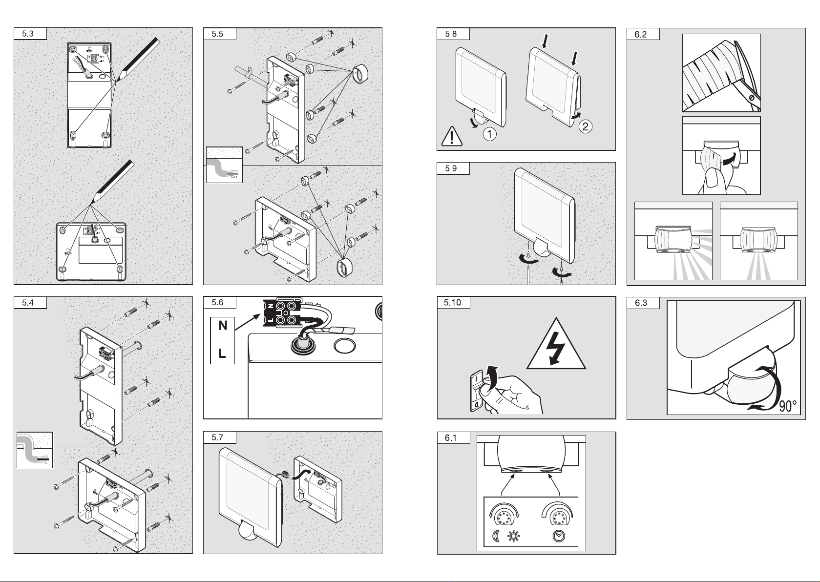
Montageschritte
(Am Beispiel L 220 LED)
• Stromversorgung abschalten (Abb� 4�1).
• Leuchtengehäuse vom Wandhalter trennen,
dabei auf die Position des Sensors achten
(Abb� 5�2).
• Bohrlöcher anzeichnen (Abb� 5�3).
• Löcher bohren und Dübel einsetzen
(Unterputzzuleitung Abb� 5�4).
• Löcher bohren und Dübel einsetzen (mit Ab-
standhaltern bei Aufputzzuleitung Abb� 5�5).
• Anschlusskabel anschließen (Abb� 5�6).
• Steckverbindungen anschließen (Abb� 5�7).
• Leuchtengehäuse (A) auf Wandhalter (C)
aufstecken. Aufsteckverbindungen sowie auf die
Position des Sensors achten (Abb� 5�8).
• Leuchtengehäuse mit Schrauben fixieren
(Abb� 5�9).
• Stromversorgung einschalten (Abb� 5�10).
• Einstellungen vornehmen ➔ „6� Funktionen“.
6� Funktionen
Nachdem das Leuchtengehäuse montiert und der
Netzanschluss vorgenommen ist, kann die Sensor-
Leuchte in Betrieb genommen werden.
Werkseinstellungen:
Dämmerungseinstellung:
Tageslichtbetrieb, 2000 Lux
Zeiteinstellung: 8 s
Dämmerungseinstellung/Ansprechschwelle
(Abb� 6�1)
–Stufenlos einstellbare Ansprechschwelle des
Sensors von 2-2000 Lux.
–Einstellregler auf = Tageslichtbetrieb,
ca. 2000 Lux.
–Einstellregler auf = Dämmerungsbetrieb,
ca. 2 Lux.
Zeiteinstellung (6�1)
–Stufenlos einstellbare Leuchtdauer von 8 s - 35 min.
–Bei Einstellung des Erfassungsbereichs wird
empfohlen die kürzeste Zeit zu wählen.
–Einstellregler kürzeste Zeit = ca. 8 s.
–Einstellregler längste Zeit = ca. 35 min.
Justierung des Erfassungsbereiches /
Reichweiteneinstellung
–In Abhängigkeit von der Montagehöhe kann der
Erfassungsbereich bei Bedarf optimal eingestellt
werden. Die Abdeckfolie dient dazu Linsenseg-
mente abzudecken und somit die Reichweite
individuell einzuschränken, z.B. um Gehwege
oder Nachbargrundstücke auszugrenzen
(Abb� 6�2).
–Die Reichweite kann durch senkrechtes
Schwenken des Sensors (D) um 90° von
2-10 m justiert werden. (Abb� 6�3)�
7� Funktionsgarantie
Dieses Steinel-Produkt ist mit größter Sorgfalt
hergestellt, funktions- und sicherheitsgeprüft nach
geltenden Vorschriften und anschließend einer
Stichprobenkontrolle unterzogen. Steinel über-
nimmt die Garantie für einwandfreie Beschaffenheit
und Funktion. Die Garantiefrist beträgt 36 Monate
und beginnt mit dem Tag des Verkaufs an den Ver-
braucher. Wir beseitigen Mängel, die auf Material-
oder Fabrikationsfehlern beruhen, die Garantieleis-
tung erfolgt durch Instandsetzung oder Austausch
mangelhafter Teile nach unserer Wahl. Eine Garan-
tieleistung entfällt für Schäden an Verschleißteilen
sowie für Schäden und Mängel, die durch unsach-
gemäße Behandlung oder Wartung auftreten. Wei-
tergehende Folgeschäden an fremden Gegenstän-
den sind ausgeschlossen.
Die Garantie wird nur gewährt, wenn das unzerleg-
te Gerät mit kurzer Fehlerbeschreibung, Kassenbon
oder Rechnung (Kaufdatum und Händlerstempel),
gut verpackt, an die zutreffende Servicestation ein-
gesandt wird.
Reparaturservice:
Nach Ablauf der Garantiezeit
oder Mängeln ohne Garantie-
anspruch fragen Sie Ihre nächste
Servicestation nach der Möglich-
keit einer Instandsetzung.
D

– 8 – – 9 –
8� Technische Daten
Abmessungen (B/H/T) L 240/L 244 LED 165 x 305 x 81
L 220/L 224 LED 246 x 251 x 84
Netzanschluss 220-240 V, 50/60 Hz
Leistung L 220 7,5 W 550 lm 73,3 lm/W
L 224 7,5 W 410 lm 54,7 lm/W
L 240 7,5 W 570 lm 76,0 lm/W
L 244 7,5 W 500 lm 66,7 lm/W
Lichtfarbe 3000 K (warmweiß), SDCM 3
Farbewiedergabeindex Ra ≥ 80
LED Lebensdauer 50.000 h (L70B10 nach LM80)
Sensortechnik Passiv-Infrarot
Erfassungswinkel 180°
Reichweite max. 10 m
Zeiteinstellung 8 s - 35 min
Dämmerungseinstellung 2-2000 Lux
Schutzart IP 44
Schutzklasse II
Schlagfestigkeit IK 07
Temperaturbereich -20 bis +50 °C
9� Betriebsstörungen
Störung Ursache Abhilfe
SensorLeuchte
ohne Spannung
■Sicherung defekt, nicht einge-
schaltet, Leitung unterbrochen
■neue Sicherung, Netzschalter
einschalten; Leitung mit
Spannungsprüfer überprüfen
SensorLeuchte
schaltet nicht ein
■Umgebung noch zu hell
■Netzschalter AUS
■Sicherung defekt
■Erfassungsbereich nicht gezielt
eingestellt
■warten bis Ansprechschwelle er-
reicht ist oder Wert neu einstellen
■Einschalten
■neue Sicherung, evtl. Anschluss
überprüfen
■neu justieren
SensorLeuchte
schaltet nicht aus
■dauernde Bewegung im
Erfassungsbereich
■Bereich kontrollieren und
evtl. neu justieren
SensorLeuchte
schaltet unerwünscht ein
■Erfassung von z.B. Autos auf der
Straße
■Bereich kontrollieren und
evtl. neu justieren
Reichweitenänderung ■andere Umgebungstemperaturen ■bei Kälte Sensorreichweite
durch Abschwenken verkürzen,
bei Wärme höher stellen
GB
1� About this document
Please read carefully and keep in a safe place�
–Under copyright. Reproduction either in whole or
in part only with our consent.
–Subject to change in the interest of technical
progress.
Symbols
!
Hazard warning!
... Reference to other information in the
document�
2� General safety precautions
!
Disconnect the power supply before
attempting any work on the unit�
• During installation, the electric power cable to be
connected must not be live. Therefore, switch off
the power first and use a voltage tester to make
sure the wiring is off-circuit.
• Installing these lights involves work on the mains
voltage supply; installation must therefore be car-
ried out professionally in accordance with the ap-
plicable national wiring regulations and electrical
operating conditions (D-VDE 0100, a-ÖVE/
ÖNORM E 8001-1, h-SEV 1000)
• Only use genuine replacement parts.
• Repairs may only be made by specialist work-
shops.
3� L 220 LED / L 224 LED
L 240 LED / L 244 LED
Proper use
–Sensor-switched outdoor light with LEDs as
the light source.
–Suitable for wall mounting outdoors.
The L 220 / L224 LED and L 240 / 244 LED
sensor-switched outdoor lights, referred to in the
following as lights, are active motion detectors.
Movement activates light. For your convenience,
safety and peace of mind. The integrated pyroelec-
tric infrared detector senses the invisible heat radi-
ated from moving objects (people, animals, etc.).
The heat detected in this way is converted
electronically into a signal that switches the light
on. Heat is not detected through obstacles, such
as walls or panes of glass, and will therefore not
activate the light.
Package contents L 240 LED / L 244 LED (Fig� 3�1)
Package contents L 220 LED / L 224 LED (Fig� 3�2)
Product dimensions L 240 LED / L 244 LED (Fig� 3�3)
Product dimensions L 220 LED / L 224 LED (Fig� 3�4)
Product components
L 240 LED / L 244 LED (Fig� 3�5)
L 220 LED / L 224 LED (Fig� 3�6)
A Light enclosure with base
B Plug-in terminal
C Wall mount
D Sensor
4� Installation
• Switch OFF power supply (Fig� 4�1)
The leads consist of three wires:
L= phase conductor (usually black, brown or grey)
N= neutral conductor (usually blue)
PE = protective-earth conductor (green/yellow)
If you are in any doubt, identify the conductors
using a voltage tester; then disconnect from the
power supply again. Connect the phase conductor
(L) and neutral conductor (N) to the terminal block.
Important:
Incorrectly wired connections will produce a short
circuit later on in the product or your fuse box. In
this case, you must identify the individual conduc-
tors once again and re-connect them. A mains
power switch for turning the unit ON and OFF may
of course be installed in the mains supply lead.
Note:
The light source in this light must only replaced by
the manufacturer or a service engineer authorised
by the manufacturer or by a similarly qualified
person.
Connect the mains power supply lead (Fig� 5�6)
Wiring diagram (Fig� 4�2)
GB

– 10 – – 11 –
5� Mounting
• Check all components for damage.
• Do not use the product if it is damaged.
• Select an appropriate mounting location, giving
consideration to sensor reach and mounting
height (Fig� 5�1).
Mounting procedure
(Based on the example of L 220 LED)
• Switch OFF power supply (Fig� 4�1).
• Detach light housing from the wall mount, paying
attention to the position of the sensor (Fig� 5�2).
• Mark drill holes (Fig� 5�3).
• Drill holes and insert wall plugs (concealed power
supply cable (Fig� 5�4).
• Drill holes and insert wall plugs (with spacers for
surface power supply cable (Fig� 5�5).
• Connect conductors (Fig� 5�6).
• Connect plug-in connectors (Fig� 5�7).
• Fit light enclosure (A) onto wall mount (C). Pay
attention to plug-in connections as well as the
position of the sensor (Fig� 5�8).
• Screw light enclosure into place (Fig� 5�9).
• Switch ON power supply (Fig� 5�10).
• Make settings ➔ "6� Functions".
6� Functions
The sensor-switched light can be put into service
after mounting the light enclosure and connecting
to the mains power supply.
Factory settings:
Twilight setting:
Daylight operation, 2000 lux
Time setting: 8 s
Twilight setting / response threshold (Fig� 6�1)
–The sensor's response threshold can be infinitely
varied from 2–2000 lux.
–Control dial set to = daylight operation,
approx. 2000 lux.
–Control dial set to = night-time operation,
approx. 2 lux.
Time setting (6�1)
–Light ON duration can be infinitely varied from
8 s - 35 min
–It is recommended that the shortest time be
selected for setting the detection zone.
–Control dial, shortest time = approx. 8 s
–Control dial, longest time = approx. 35 min
Adjusting the detection zone / reach setting
–Depending on the mounting height, the detection
zone setting can be optimised to suit require-
ments. The shroud foil can be used for masking
out any number of lens segments to limit reach
as required, e.g. to mask out paths or neigh-
bouring property (Fig� 6�2).
–Reach can be adjusted from 2-10 m by tilting
the sensor (D) through 90° (Fig� 6�3)�
7� Functional warranty
This Steinel product has been manufactured with
utmost care, tested for proper operation and safety
and then subjected to random sample inspection.
Steinel guarantees that it is in perfect condition
and proper working order. The warranty period is
36 months and starts on the date of sale to the
consumer. We will remedy defects caused by
material flaws or manufacturing faults. The warran-
ty will be met by repair or replacement of defective
parts at our own discretion. The warranty shall not
cover damage to wear parts, damage or defects
caused by improper treatment or maintenance.
Further consequential damage to other objects
shall be excluded.
Claims under the warranty will only be accepted
if the unit is sent fully assembled and well-packed
with a brief description of the fault, a receipt or
invoice (date of purchase and dealer's stamp) to
the appropriate Service Centre.
Repair service:
If defects occur outside the
warranty period or are not
covered by the warranty, ask
your nearest service station for
the possibility of repair.
8� Technical specifications
Dimensions (W x H × D) L 240 / L 244 LED 165 x 305 x 81
L 220 / L 224 LED 246 x 251 x 84
Voltage supply 220-240 V, 50 / 60 Hz
Output L 220 7.5 W 550 lm 73.3 lm/W
L 224 7.5 W 410 lm 54.7 lm/W
L 240 7.5 W 570 lm 76.0 lm/W
L 244 7.5 W 500 lm 66.7 lm/W
Colour temperature 3000 K (warm white), SDCM 3
Colour rendering index Ra ≥ 80
LED life expectancy 50,000 h (L70B10 to LM80)
Sensor technology Passive infrared
Angle of coverage 180°
Reach max. 10 m
Time setting 8 s - 35 min
Twilight setting 2-2000 lux
IP rating IP 44
Protection class II
Impact resistance IK 07
Temperature range -20° to +50°C
9� Troubleshooting
Malfunction Cause Remedy
Sensor-switched light
without power
■Fuse faulty, not switched ON,
break in wiring
■Fit new fuse, turn ON mains
switch, check wiring with voltage
tester
Sensor-switched light
will not switch ON
■Surroundings still too bright
■Mains switch OFF
■Fuse blown
■Detection zone not correctly
adjusted
■Wait until response threshold is
reached or adjust setting
■Switch ON
■Fit new fuse, check connection
if necessary
■Readjust
Sensor-switched light
will not switch OFF
■Continued movement within
the detection zone
■Check detection zone and
readjust if necessary
Sensor-switched light
switching ON when it
should not
■Cars in the street are detected,
for example
■Check detection zone and
readjust if necessary
Changing reach ■Differing ambient temperatures ■When it is cold, shorten reach
by tilting sensor down,
move it up in warm weather
GB

– 12 – – 13 –
S
1� Om detta dokument
Läs noga igenom dokumentet och förvara
det väl!
–Upphovsrättsligt skyddat. Eftertryck, även delar
av texten, bara med vårt samtycke.
–Ändringar som görs pga den tekniska utveck-
lingen, förbehålles.
Symbolförklaring
!
Varning för fara!
... Hänvisning till textställen i dokumentet�
2� Allmänna säkerhetsanvisningar
!
Bryt spänningen före alla arbeten
på produkten!
• Inkoppling måste utföras i spänningsfritt tillstånd.
Bryt strömmen och kontrollera med spännings-
provare att alla parter är spänningslösa.
• Vid installeringen av denna apparat handlar det
om arbeten på nätspänningen och därför måste
arbetet genomföras professionellt enligt respek-
tive länders installationsföreskrifter och anslut-
ningskrav (D-VDE 0100, a-ÖVE/ÖNORM
E 8001-1, h-SEV 1000)
• Använd endast originalreservdelar.
• Reparationer får bara genomföras i en auktorise-
rad verkstad.
3� L 220 LED / L 224 LED
L 240 LED / L 244 LED
Ändamålsenlig användning
–Sensorarmatur för utomhusbruk med lysdioder
som ljuskälla.
–Avsedd för väggmontering utomhus.
Sensorarmaturerna för utomhusbruk L 220/L224 LED
och L 240/244 LED, i det följande kallad armatur,
är en aktiv rörelsevakt. Ljuset tänds vid rörelse.
För din komfort och säkerhet. Den integrerade
infraröda sensorn är utrustad med en pyrosensor
som känner av den osynliga värmestrålningen från
kroppar i rörelse (människor, djur, etc.).
Den registrerade värmestrålningen omvandlas
på elektronisk väg och tänder en ansluten lampa.
Värmestrålningen registreras inte genom olika
hinder, som t.ex. väggar eller glasrutor, och då sker
ingen koppling.
Innehåll L 240 LED / L 244 LED (bild 3�1)
Innehåll L 220 LED / L 224 LED (bild 3�2)
Produktmått L 240 LED / L 244 LED (bild 3�3)
Produktmått L 220 LED / L 224 LED (bild 3�4)
Översikt över enheter
L 240 LED/ L 244 LED (bild 3�5)
L 220 LED/ L 224 LED (bild 3�6)
A Lampkupa med chassi
B Inkopplingsplint
C Väggfäste
D Sensor
4� Installation
• Bryt spänningen (bild 4�1)
Nätanslutningens matarledning består av en
3-ledarkabel:
L= Fas (oftast svart, brun eller grå)
N= Neutralledare (oftast blå)
PE = Skyddsledare (grön/gul)
Vid osäkerhet, måste kabeln identifieras med en
spänningskontroll; gör den därefter spänningsfri
igen. Fas (L) och nolledare (N) monteras i anvisad
plint.
Viktigt:
En förväxling av anslutningarna leder till kortslutning
i armaturen eller i säkringsskåpet. I ett sådant fall
måste de enskilda kablarna identifieras igen och
anslutas på nytt. I nätkabeln kan naturligtvis en
strömställare för till- och frånkoppling installeras.
Anmärkning:
Ljuskällan i denna armatur får endast bytas ut av
tillverkaren eller av en av tillverkaren auktoriserad
servicetekniker eller av en annan person med
jämförbar kvalifikation.
Kontakt nätanslutning (bild 5�6)
Anslutningsschema (bild 4�2)
5� Montage
• Kontrollera samtliga delar med avseende på
skador.
• Är produkten skadad får den inte tas i bruk.
• Välj en lämplig montageplats med hänsyn till
räckvidden och montagehöjden (bild 5�1).
Montage-ordning
(exempel L 220 LED)
• Bryt spänningen (bild 4�1).
• Ta av lampkupan från väggfästet, akta på
sensorns position (bild 5�2).
• Markera borrhålen (bild 5�3).
• Borra hål och sätt i pluggar (kabel med infällt
montage bild 5�4).
• Borra hål och sätt i pluggar (med distanser
vid utanpåliggande montage bild 5�5).
• Anslut nätkabeln (bild 5�6).
• Anslut stickkontakterna (bild 5�7).
• Montera lampkupan (A) på väggfästet (C).
Akta på stickkontakternas och sensorns position
(bild 5�8).
• Fixera lampkupan med skruvar (bild 5�9).
• Slå till spänningen (bild 5�10).
• Företa inställningarna ➔ "6� Funktioner".
6� Funktioner
När lampkupan är monterad och armaturen är
ansluten, är sensorarmaturen klar att användas.
Fabriksinställningar:
Skymningsinställning:
dagsljusdrift, 2000 lux
Efterlystid: 8 sek
Skymningsnivå/aktiveringsnivå (bild 6�1)
–Sensorns aktiveringsnivå kan ställas in steglöst
från 2-2000 lux.
–Ställskruven på = dagsljusdrift, ca 2000 lux.
–Ställskruven på = skymningsdrift, ca 2 lux.
Efterlystid (6�1)
–Efterlystiden kan steglöst ställas in från
8 sek - 35 min.
–Vid inställning av bevakningsområdet
rekommenderas att välja den kortaste tiden.
–Ställskruv kortaste tid = ca 8 sek
–Ställskruv längsta tid = ca 35 min
Justering av bevakningsområdet /
inställning av räckvidden
–Beroende av montagehöjd kan bevaknings-
området efter behov ställas in optimalt. Täck-
folien är till för att täcka linssegment för att indivi-
duellt kunna begränsa räckvidden, t.ex. för att
avgränsa gångvägar eller angränsande tomter
(bild 6�2).
–Genom att vrida sensorn (D) vertikalt 90° kan
räckvidden justeras med 2-10 m. (bild 6�3)�
7� Funktionsgaranti
Denna Steinel-produkt är tillverkad med störs-
ta noggrannhet. Den är funktions- och säkerhets-
testad enligt gällande föreskrifter och har därefter
genomgått en stickprovskontroll. Steinel garante-
rar felfritt tillstånd och felfri funktion. Garantin gäller
i 36 månader från inköpsdagen. Vi åtgärdar brist-
fälligheter orsakade av material- eller tillverkningsfel.
Garantin uppfylls genom reparation eller utbyte av
bristfälliga delar efter vårt val. Garantin omfattar inte
slitage och skador orsakade av felaktigt hanterande
eller bristande underhåll och skötsel av produkten.
Följdskador på främmande föremål ersätts ej.
Garantin gäller endast då produkten, som inte får
vara demonterad, sändes väl förpackad med kort
beskrivning av felet och fakturakopia eller kvitto
(inköpsdatum och stämpel) till vår representant
eller lämnas till inköpsstället.
Reparationsservice:
Kontakta nästa serviceställe för
reparationer efter garantitidens
utgång eller vid bristfälligheter
som inte omfattas av garantin.
S

– 14 –
8� Tekniska data
Mått (B/H/D) L 240/L 244 LED 165 x 305 x 81
L 220/L 224 LED 246 x 251 x 84
Spänning 220-240 V, 50/60 Hz
Effekt L 220 7,5 W 550 lm 73,3 lm/W
L 224 7,5 W 410 lm 54,7 lm/W
L 240 7,5 W 570 lm 76,0 lm/W
L 244 7,5 W 500 lm 66,7 lm/W
Ljusfärg 3000 K (varmvit), SDCM 3
Färgåtergivningsindex Ra ≥ 80
LED livslängd 50.000 h (L70B10 enligt LM80)
Sensorteknik Passiv-infraröd
Bevakningsvinkel 180°
Räckvidd max.10 m
Efterlystid 8 sek - 35 min
Skymningsinställning 2-2000 lux
Skyddsklass IP 44
Isolationsklass II
Slagtålighet IK 07
Temperaturområde -20 till +50 °C
9� Driftstörningar
Störning Orsak Åtgärd
Sensorarmaturen
utan spänning
■Säkring defekt, inte påkopplad,
strömförsörjning avbruten
■Byt säkring, slå till spänningen;
testa med spänningsprovare
Sensorarmaturen
tänds inte
■Omgivningen för ljus
■Nätströmbrytare FRÅN
■Säkring defekt
■Bevakningsområdet felinställt
■Vänta tills aktiveringsnivån har
uppnåtts eller justera värdet
■Slå till
■Byt säkring, kontrollera evtl.
anslutningen
■Justera inställningen
Sensorarmaturen
släcks inte
■Ständig rörelse i bevaknings-
området
■Kontrollera området och ställ in
på nytt om nödvändigt
Sensorarmaturen
tänds spontant
■Rörelser från t.ex. bilar ute på
gatan
■Kontrollera området och ställ in
på nytt om nödvändigt
Ändring av räckvidden ■Ändrade omgivningstemperaturer ■Vid kyla - vrid sensorn neråt
för att förkorta räckvidden,
vid värme - ställ den högre
This manual suits for next models
3
Table of contents
Languages:
Other STEINEL Landscape Lighting manuals
Popular Landscape Lighting manuals by other brands

Eurofase Lighting
Eurofase Lighting HYDROFLOOR MINI ROUND instruction manual

RUSTA
RUSTA GUNNERSBURY 3W manual

Saxby Lighting
Saxby Lighting Canillo 67699 instruction manual

Paradise Datacom
Paradise Datacom U000-1010 installation manual

Malibu Boats
Malibu Boats LZ21811K instructions

Brinkmann
Brinkmann Metal owner's manual