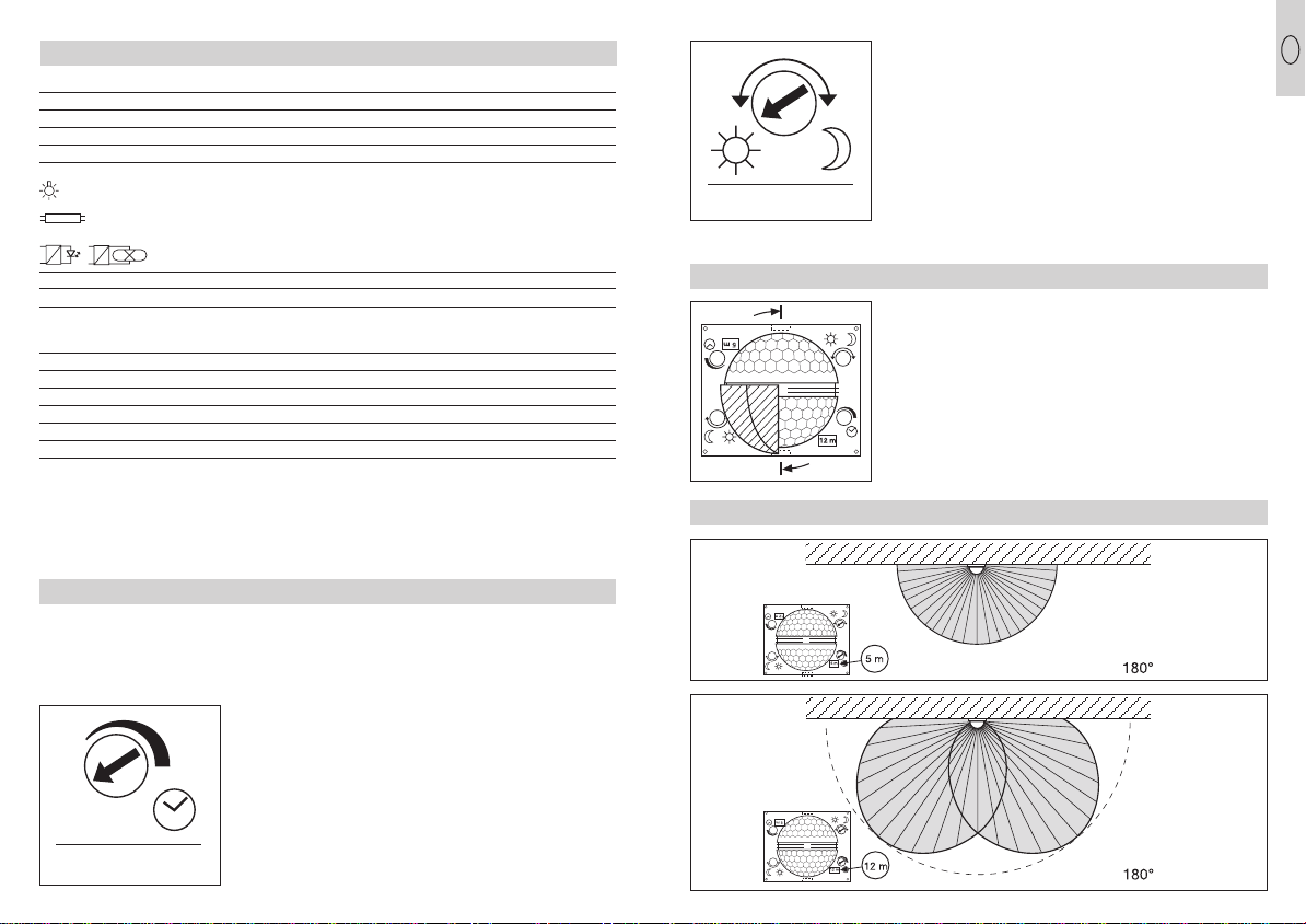
Functions
After the mains connection
has been made, the hous-
ing has been closed and
the lens has been applied,
the unit can be commissio-
ned. Two setting options
are concealed behind the
decorative cover .
Important: perform time-
and twilight setting only
with the lens installed.
Switch-off delay
(time setting)
The desired period of oper-
ation of the sensor halogen
light can be adjusted conti-
nuously from approx.
10 sec. to a max. of 15 min.
When the adjustment screw
is at the left stop position,
this means the shortest
time of up to 10 sec. When
the adjustment screw is at
the right stop position, this
means the longest time of
approx. 15 min. It is recom-
mended to select the shor-
test time when setting the
detection zone and for the
functional test.
15
HS 502: HS 152 XENO:
Dimensions (H x W x D): 235 x 220 x 155 mm 235 x 160 x 140 mm
Weight: 2060 g 1400 g
Connection: 230–240 V, 50 Hz 230–240 V, 50 Hz
Output: 500 W max./ R7S 150 W max./ R7S
Additional switching capacity: 500 W max. *1) 800 W max. *1)
300 W max., 400 W max.,
cos ϕ= 0,5 *2) cos ϕ= 0,5 *2)
2 x 58 W each, 4 x 58 W each,
C ≤44 µF *3) C ≤88 µF *3)
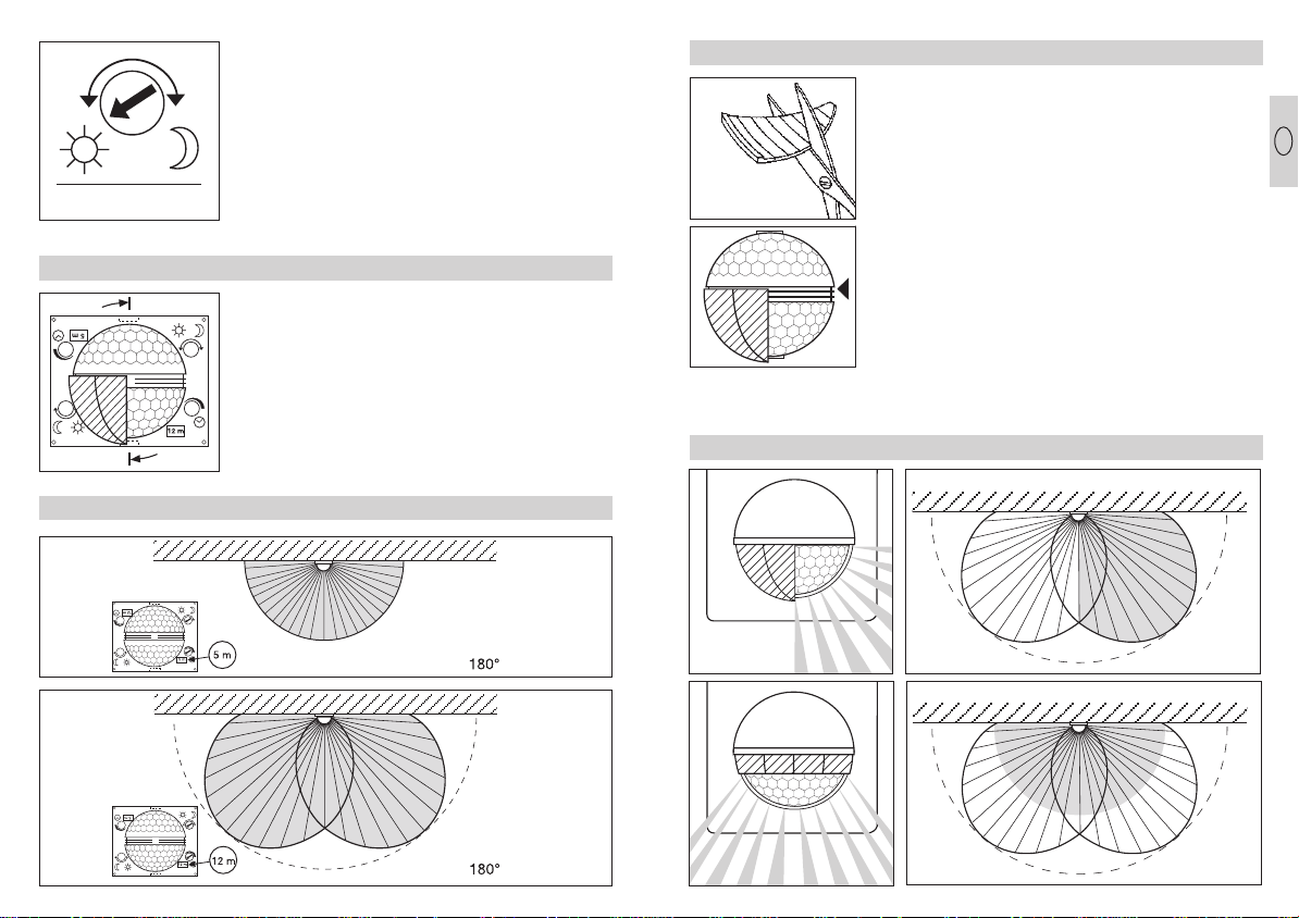
Angle of coverage: 180° horizontal, 90° vertical
Area illuminated by floodlight: 375 cm2max. 300 cm2max.
Sensor reach: basic setting 1: max. 12 m (factory setting)
basic setting 2: max. 05 m
+ fine adjustment via shrouds 1–12 m
Time setting: 10 sec.–15 min. (factory setting 10 sec.)
Twilight setting: 2–2000 lux (factory setting: 2000 lux)
Enclosure: IP 44
Safety class: I (with earth conductor connection)
Swivelling range of halogen light: vertical: 40°, horizontal: 30°
Temperature range: -20 °C – +50 °C
*1) Filament bulbs, 500 W max. (HS 502) / 800 W max. (HS 152 XENO) operating on 230 V AC
*2) Fluorescent lamp, 300 W max. (HS 502) / 400 W max. (HS 152 XENO) at cos ϕ= 0.5,
inductive load at 230 V AC
*3) Fluorescent lamps, low-energy bulbs, LED lights with electronic ballast (total capacity of all connected
ballasts below the value specified) operating on 230 V AC
Technical specifications
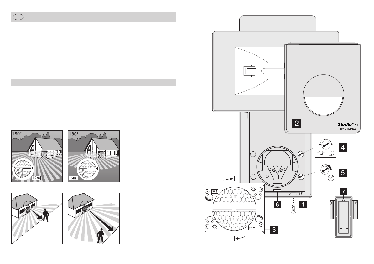
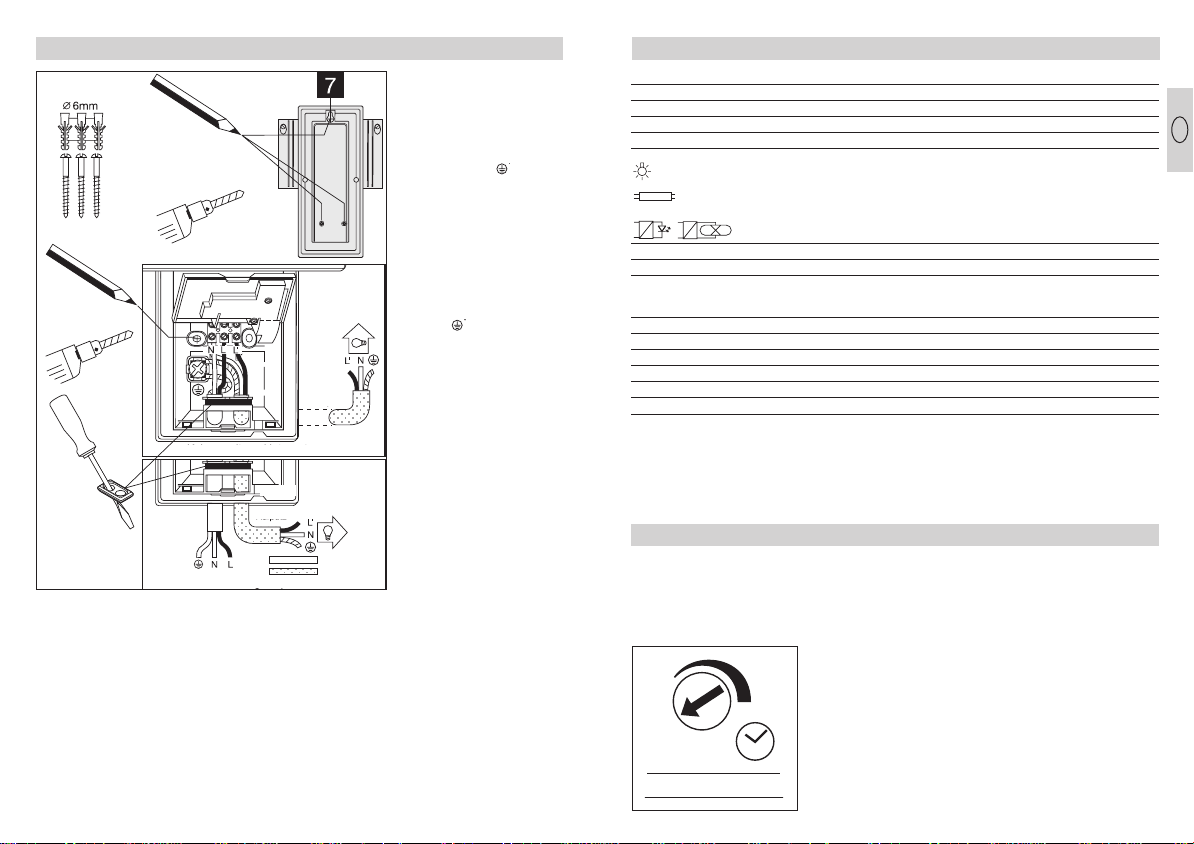
Installation height:
In order to achieve the given
reach of 5/12 m, the instal-
lation height should be
approx. 2 m.
Installation steps:
1. Remove decorative cover
, 2. Insert positioning
screw, 3. Fit sensor halo-
gen light in position, 4. Fold
up installation housing ,
5. Mark drilling holes and
remove sensor halogen
light. 6. Drill the holes and
insert plugs (6 mm dia.).
7. Insert sealing plugs.
8. Wire up the supply and
service leads, if required
and connect. 9. Screw
housing firmly into place.
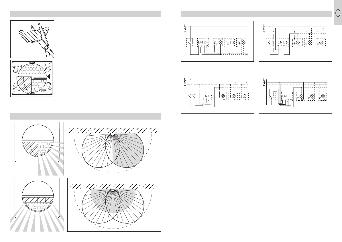
Installation/Wallmounting
a) Connection of the
supply lead
The supply lead consists
of a 3 phase cable:
L = phase conductor
N = neutral conductor
PE = protective-earth
conductor
If in doubt, the cable must
be identified with a voltage
tester. Switch off the cur-
rent again. The phase (L)
and neutral (N) conductors
are to be connected
according to the terminal
assignment. The protective
earth conductor (PE) must
be clamped to the earth
contact ( ). A mains switch
for ON and OFF switching
can of course be installed
in the mains lead.
Alternatively the sensor can
manually be activated for
the selected time by an
opening switch contact in
the power supply.
b) Connection for an addi-
tional consumer:
An additional consumer can
be connected to the sensor
halogen light. Please obser-
ve the maximum permitted
output in this case (refer to
technical specifications).
The current carrying con-
ductor of the consumer is
connected to the terminal
marked L’. The neutral con-
ductor of the consumer is
clamped to the terminal
marked Ntogether with the
supply lead neutral conduc-
tor. The protective earth
conductor is to be connec-
ted to the earth contact.
Important: if the connec-
tions are reversed, the
appliance may be
damaged.
14
Flush mounted wiring
flush
mounted
surface mounted
Supply lead
Service lead
Surface mounted wiring
GB
HS_152_502_10spr_aktuell 29.04.2011 13:56 Uhr Seite 15
PK
Elektronik
Vertriebs
GmbH,
E-Mail:
[email protected],
Internet:
www.pkelektronik.com
Steinel Sensor-Halogenstrahler HS 152 XENO