steinert KM 1400 SE User manual

Operating Manual
Woodturning Lathe KM 1400 SE
1
main power, magnetic box with button
and switches
pin to lock spindle, standard accessories
handle for motor pulley
2
indexing function
3
manual, safety advises, maintenance
4
declaration of conformity

Digitale Anzeige der Drehzahl
display for adjusted spindle speed
indicateur electronique pour vitesse
Hauptschalter/Not-Aus-Taster
main power/emergency-off
commutateur prinicipal/ârret d`urgence
Bewegliche Bedienbox mit Magnet,
Ein-/Aus-Schalter, Drehzahlregler,
RS/LS-Lauf Schalter
moveable magnetic box with
spindle
speed
regulation
n knob,
on-off button spindle,
forward/reverse switch
mobile box magnétic avec
interrupteur de mise en marche et
d`arrêt, marche arrière et avant,
bouton de régulation de la vitesse
de l`arbre
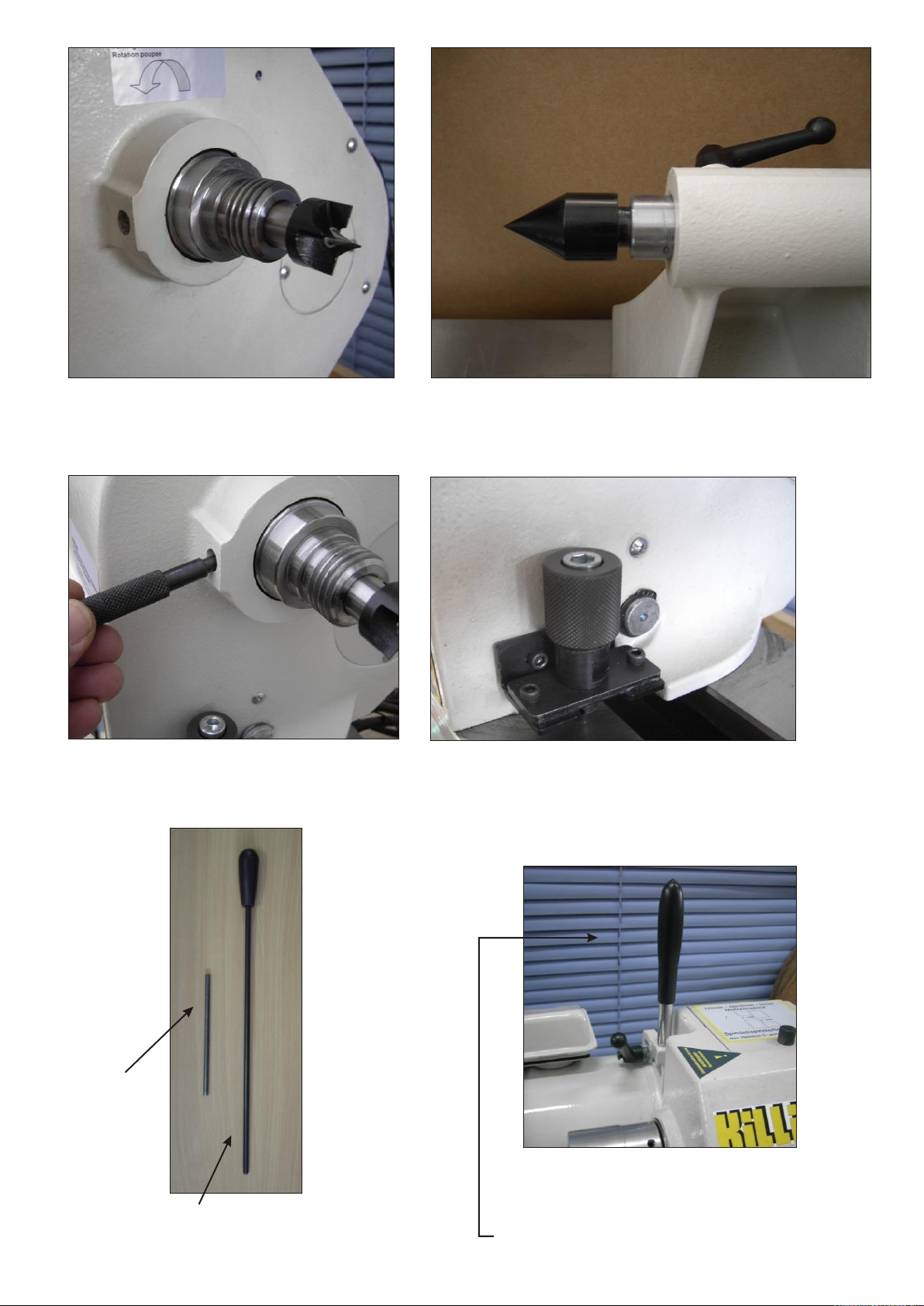
Vierzack Mitnehmer in Spindel eingesetzt
prong mandrel on spindle/headstock
pointe d’entrainement a poupée fixe
Mitlaufende Körnerpitze im Reitstock
live centre fastenend in quill of tailstock
contre pointe tournante fixation poupée mobile
Stift für Spindelblockierung
pin to lock spindle
goupille pour d`arrêt la broche
Rasterstift für Spindelstockdrehung
locking pin for headstock swivelling
levier d`arrêt pour fixation le poupée
Steckstift zum Futterlösen
pin to loosen chucks
pin pour détacher le mandrin
Ausschlagstange für Mitnehmer
bar/rod to knock out prong from spindle
tige d`ejection de la pointe entrainement
Hebel Motorwippe (kann aus Sicherheitsgründen
zum Transport demontiert sein)
handle for motor pulley (could be dismounted
for transport)
levier de tension de la courroie

Indexstift für Teilungen
pin for indexing
goupille pour indexeur

OPERATING INSTRUCTIONS KM 1400 SE 04-2019
Modified series 09-2009 and revised 08-2013
STANDARD FITTINGS
1 4-prong-mandrel MT 2 (for spindle/headstock)
1 live centre MT 2 tip 60° (for tailstock)
1 locking pin (indexing pin) with threaded spindle (for indexing)
1 center knock-out rod (to knock out the prong-mandrel)
1 tool rest bottom part
1
tool rest upper part 350 mm
TECHNICALSPECIFICATIONS
Centre height 180 mm
Distance between centres 760 mm (standard)
Bed extension 450 mm (optional)
Swing over bed 360 mm
Swing with outrigger appr. 600 mm (option)
Spindle thread M 33 with centering collar, inner cone MT 2
Spindle speed 2steps: 60-1.300 150-3.025 rpm/min.
Max. permissible workpiece D 400 mm 130 mm
Tailstock MT 2 quill taper, stroke 70 mm
Spindle motor 230 V/3 ph/1 hp/50 Hz,
inverter electric mains 230 V/1 ph/50 Hz
Vee-belt poly-vee-belt J210 6 ribs
Electrical system with undervoltage and overload protection
.
Dimensions L/W/H min. 1.350 x 520 x 580 mm benchtype
Weight appr. 96 kg benchtype
Paint grey-white RAL 9002/anthrazit RAL 7016
Warranty 1 year
Subject to change without alterations
The machine goes conform with CE-regulations
LIABILITY
It is not permitted to make alterations or additions to the construction of the machinery supplied, to parts of the machinery
supplied or to accessories. Any warranty and liability claims become void in such case.
SETTING UP THE MACHINE
The anti-rust protection must be removed from the bright machine parts and from the inner cone
of spindle and tailstock before first use
BENCHMODEL
use a strong and stable workbench with a minimum length of 115 cm that the footplates on left-reighthandside can
be fastened securely to the workbench
Important advice:
The inverter is fixed under the lathe bed. To ensure ventilation and to avoid overheating it is necessary
To keep this aerea clean from dust and chips ! Constantly remove chips and dust by sweeping or exhausting
Do NOT USE compressed air!

STANDMODEL
If the casting legs are ordered with the machine the lathe comes completely mounted
in case legs are ordered later:
remove the foot- plates left/righthandside from the benchmodel
place machine transverse onto a workbench and mount legs from below to the lathe bed
level the machine with set-screws M12 supplied with the legs
ELECTRIC CONNECTION
The lathe is supplied complete with a plug 230 V/1 ph for electric mains
OPERATING THE MACHINE
The lathe is switched on/off by the main switch fixed at the headstock
Before pushing the green button at mobile box = “on” for spindle adjust the potentiometer to “0”-Zero!
Danger of Accident !
SPEED REGULATION
Turning the potentiometer clockwise: increasing of speed, see display
The adjusted speed is only shown if the spindle is running.
Regulation of spindle speed with the potentiometer only if the spindle is running
Infinitely variable speed with 2 pulley-steps
1 step: 0-1300 rpm/min
2
step: 0-3100 rpm/min
Use 1step of pulley if working with appr. 300 rpm, this ensures a sufficient power in the lower speeds
CHANGING THE VEE-BELT TO THE REQUESTED PULLEY STEP
switch mainswitch to “Zero” before opening the vee-belt cover
-
loosen the motor clamping by handle, move it forwards
-
change vee-belt onto the requested pulley step by “moving” the pulley by hand forward/reverse
(easier handling)
-
fasten clamping lever : do not use too much tension because high tension can cause
Vibration, wear of bearings and veebelt, could also cause damage on the motor-schaft
-
close vee-belt pulley correctly otherwise the motor will not run (safety switch inside)
SPINDLE SPEED AND WORKPIECE DIAMETER
The maximum workpiece diameter which is allowed at the
maximum spindle speed of 3.025 rpm: D=130 mm
Watch the stickers on headstock for the adjusted speed and the max. workpiece diameter
CHANGING THE TURNING DIRECTION/ROTATION OF SPINDLE
correct turning direction = lefthand rotation, anti-clockwise
in any case:
the righthand/clockwise rotation may be used only if chucks are used or supplied
with optional security locking!
the flip switch/or selector for forward/reverse is at the movable box:
Before changing the direction turn the potentiometer to “Zero”
when changing the turning direction the inverter will automatically slow down the speed:
spindle starts slow in opposite direction, speed increases again as adjusted before
Caution
to meet the safety regulation: adjust the lowest spindle speed before changing the spindle direction.
Chucks may be used only if supplied with optional security locking!

Emergency-Off-Button
The main switch on headstock is also used as emergency-off-button
If the emergency-off-button was pressed down the button must be turned to activate electric power.
MOVABLE OPERATING BOX
The box is equipped with a “magnet” and can be placed at any position onto the lathe bed
Switches with following functions
Green button = “on”
Red button = “off”
Speed regulator or potentiometer = rotable knob :
Clockwise = increasing the rpm
Anti-clockwise = decreasing the rpm
Turning direction of spindle fwd/rev
Attention: the correct working direction for turning is lefthand i.e. anticlockwise !
SWIVELLING OF HEADSTOCK
the headstock can be swivelled in 6 different positions: 0/45/90/135/270°
Do not swivel headstock if spindle motor is turning, switch machine “Off”
-
loosen the headstock fixing lever on lefthand side of headstock
-
loosen the pin in front of headstock by turning it anticlockwise until you can lift it
-
rotate the headstock to one of the 6 possible positions:
the pin must properly locked into the position
take care of your fingers, do not squeeze them between lathe bed
-
turn pin clockwise to fix the position
-
tighten the headstock fixing lever
INDEXING ON SPINDLE
The spindle is blocked by using the threaded locking pin
the spindle is having 12 borings on its circumference = 30° division
if the threaded pin is screwed into one of the two additional borings it can be blocked at 15° and 10°
Caution:
before the machine/spindle is switched on
-
unscrew the indexing pin (Handwheel side) remove it
-
remove also fixing pin from casting nose in front of spindle
OPERATING CHUCKS
The chucks are mounted on the external thread M 33 of the spindle
Swtich off spindle motor
block spindle with fixing pin
screw on the chuck and, fasten it properly using the pin
Caution: remove the pin before switching on spindle
True running is possible only when the chuck faces bear tightly against the spacer of spindle.
Do not use spindle motor power to fasten your chuck: you might get problems unscrewing the
chuck from spindle
Caution: if direction of spindle is changed to righthanded rotation secure the chuck against
running off the spindle (security lock: option, if chucks are ordered with the machine)
prong mandrel on spindle/headstock: knock out with bar
live centre on tailstock: turn handwheel until centre is released from quill, hold centre by hand to
avoid falling out
Caution: loosen the clamping lever of quill before turning the handwheel

SAFETY REGULATIONS
-
The belt guard must be reclosed after each change of V-belt position, motor does not run if not properly closed
-
Before the machine is switched on:
turn potentiometer to “0”,
after motor is switched o: the selected speed must be checked against the maximum permissible workpiece diameter,
-
Large, out-of-balance workpieces must be machined at minimum speed,
cut them by a bandsaw octagonal to decrease out-of-balance
-
All clamping levers i.e. spindle-/tailstock, tool rests etc must be tightened before beginning to work,
any operating pins /keys must be removed from chucks or spindle!
CLAMPING THE WORKPIECE
Turning between centres with the 4-prong-mandrel and live centre:
Roughly centre the workpiece at both ends outside the lathe (make bearings last longer)
that markings are visible.
Press the driver prongs firmly into the workpiece by turning the hand wheel.
Tighten the set screws for the tail stock and the quill.
Overhung turning with chucks
-
Cone-shaped chuck: Taper turn the workpiece to suit the chuck diameter and drive it in with heavy blows.
-
Heureka-chuck: Drive the face of the unmachined workpiece into the chuck so that the sharp edge penetrates
approx. 10-15 mm . Maximum work length 200 mm. Most suitable for soft wood.
-
Face plate: Secure the wooden discs with wooden screws through the bores provided.
-
Disc-chuck: Screw the workpiece into the wooden screw (if necessary, drill core hole. Wooden discs can be
used to limit the depth of penetratin of the screw).
-
Jaw-chucks: Increased risk to operator with jaws which project beyond the chuck body. Remove the tightening
key before starting the machine.
-
div.chucks i.e. Nova Chuck, Super Nova etc. see separate operating manual
TOOL REST
move the tool rest as close as possible to the workpiece, re-adjust it during the work. Take care of the square dimension
of your workpiece. Move tool rest just if workpiece is not turning. Clamp fastening screws.
OUTRIGGER= EXTERNAL TURNING ATTACHMENT (Option)
instruction and photo supplied if option was ordered
.
BED EXTENSION (Option)
instruction supplied if option was ordered
MAINTENANCE
The machine requires no maintenance. The ball bearings are closed-off dust-proof and must not be lubricated.
Bright parts should be oiled occasionally to prevent corrosion.
Expecially when worked with “whet” wood: clean the machine blank parts and oil them immediately
You also can use a special anti-corrosion spray like WD40 for all blank metal parts
Movable parts i.e. indexing pin, excenter shaft of tool rest, quill and spindle should be oiled (or use anti-corrosion spray)
between 4-6 month to ensure true running and prevend seizing up.
CENTERING TIP TO TIP: “0”- Point Position Headstock to Tailstock
The following parts are optional available if it is necessary to align the both tips exactly
06.200.206 extension bush MT2/MT2 x 250mm
03 900.310 cone MT2/B16
How to use it:
-
fix both parts cone to cone
-
insert this “centering device” with cone into the cone of headstock

-
move tailstock with inserted live centre close to the headstock resp. countersink of cone
-
tighten clamping lever of tailstock
-
loosen the clamping lever of headstock
-
align the headstock to the tip of live centre in tailstock and move the quill byturning the handwheel
into the countersink of cone
-
tighten quill and tighten headstock
The headstock is now adjusted correct into a “0” Position
-
loosen clamping lever of tailstock and move tailstock back
-
push out the inserted “centering device” from spindle by using the long bar
ACCESSORIES, ATTACHMENTS and COPYING UNITS
All recommended and available accessories see special accessory leaflet.
Drechselzentrum Erzgebirge
Heuweg 4
09526 Olbernhau
Deutschland
Tel./Phone: +49 (0)37360-6693-0
Fax/Fax: +49 (0)37360-6693-29
Shop www.drechslershop.de
Mail: [email protected]

CE-Konformitätserklärung / CE - Declaration of Conformity
für / for
Handdrechselbank / Woodturning lathe:
killinger® KM1400
Wir / We: DRECHSELZENTRUM ERZGEBIRGE –steinert®
Heuweg 4, 09526 Olbernhau, Deutschland/Germany
Tel./Phone: +49 (0)37360-6693-0
Fax/Fax: +49 (0)37360-6693-29
E-Mail/Email: [email protected]
Internet/Internet: www.drechslershop.de
erklären, dass die zuvor benannte Maschine den Anforderungen der Maschinen-Richtlinie 2006/42/EG
entspricht.
declare that this machine named above meets the essential health and safety requirements of machinery
directive 2060/42/EC.
Elektrische und elektronische Komponenten entsprechen den Anforderungen der Niederspannungsrichtlinie
2006/95/EC und der EMV-Richtlinie 2004/108/EG.
Electrical control and its Components are in accordance with the Low Voltage (2006/95/EC) and EMC
(2004/108/EC) Directives
Angewandte harmonisierte Normen / Harmonized standards applied:
EN ISO 12100 EN ISO 3746
EN ISO 13857 EN ISO 11202
EN ISO 13850 EN ISO 11204
EN 13849-1 EN 60 204 T 1
EN 1088
Diese Erklärung wird verantwortlich für DRECHSELZENTRUM ERZGEBIRGE -steinert® abgegeben durch:
This declaration is made for and on behalf of DRECHSELZENTRUM ERZGEBIRGE -steinert® by:
Roland Steinert (Inhaber / Owner)
Unterschrift:_______________________________________

Table of contents
Other steinert Lathe manuals


Popular Lathe manuals by other brands


Axminster Craft
Axminster Craft AC370WL Original instructions

The Cool Tool
The Cool Tool UNIMAT 1 BAsic Instructions for use

HARVEY
HARVEY T-40 user manual

Gude
Gude GDM 1000 Translation of original operating instructions

Clarke
Clarke CWL1000B Operation & maintenance instructions

TMG
TMG TMG-PAT24 product manual

Di-Acro
Di-Acro Number 2 Power Operated Notcher Operators manual & instructions

Rikon Power Tools
Rikon Power Tools 70-100 instruction manual

MasterCraft
MasterCraft 055-4504-8 instruction manual

IKH
IKH XWS003 instruction manual

Southbend
Southbend SB1309 instruction sheet

Southbend
Southbend SB1051 owner's manual