Di-Acro Number 2 Power Operated Notcher User manual
Di-Acro, Incorporated
PO Box 9700
Canton, Ohio 44711
3713 Progress Street N. E.
Canton, Ohio 44705
330-455-1942
330-455-0220 ( ax)
Revised 01/02
NUMBER 2 POWER
NUMBER 2 POWER
OPERATED NOTCHER
OPERATED NOTCHER
Sale or distribution o manuals is strictly prohibited
without the express written consent o Di-Acro, Incorporated
OPERATOR’S MANUAL & INSTRUCTIONS

Smooth, even notches can be cut in all types o ductile material with the Di-Acro Notcher. It elimi-
nates the high cost o special dies required or each di erent notching operation and does away
with time wasted in punch press setup—you simply adjust the Material Gauge and you’re ready or
production.
Both power and hand operated models o this precision machine are available. They are equally
use ul in the experimental shop or on the production line.
Adjustable gauges are used to locate a notch o any dimension at the corner o a sheet o material
or at any position along the edge o the sheet. Notches greater or less than 90 degrees can be
obtained in two operations and many straight shearing operations can also be per ormed. The
hardened and ground Triangular Ram used in the Di-Acro Notcher will provide years o continuous,
trouble- ree per ormance and assure a clean cut ree rom rough edges or burr.
SETUP PROCEDURE
POWER NOTCHER
Except or wiring, the power operated Di-Acro Notcher is delivered ready or operation. To set up,
simply hook up wiring, adjust Gauges or the proper size notch and machine is ready or production.
WIRING
Cost includes wiring or either o the ollow-
ing standard electrical systems.
110 or 220 volt single phase
220 or 440 volt three phase
Hook up lead-in wires and switch Motor on
to check the direction o Flywheel. It should
operate in a counter-clockwise direction as
indicated by the arrow.
I the lead-in wires have been incorrectly
hooked up, Tripping Mechanism will ail to
operate. To remedy this, simply reverse any
two lead-in wires.
TO PREVENT SERIOUS BODI Y INJURY
AND DAMAGE TO THE MACHINE
BO T THE MACHINE TO THE STAND
AND THE STAND TO THE F OOR
CAUTION
WIRING
2

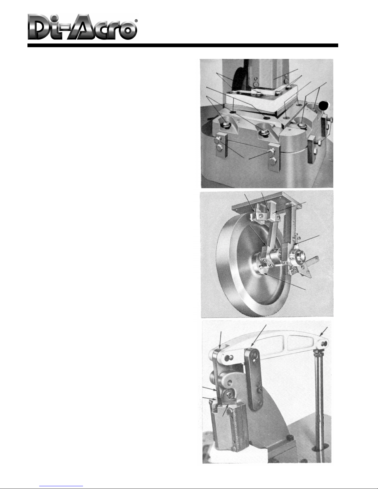
CAUTION: Be sure ram will clear material gauges
be ore operating machine.
SETUP
A. Change size of tab (set at factory for 1/2” tab)
Loosen bolts (A) holding lower blade to blade
carrier (do not remove).
Slide blades orward or back, holding them
against shoulder machined in blade carrier to
obtain desired tab.
Tighten bolts (A).
Loosen bolts (B).
Lower ram until upper blades pass by lower
blades (it may be necessary to slide one upper
blade back).
Slide blade (C) orward into notch in lower
blade. Tighten bolts.
Slide blade (D) orward until it contacts blade
(C). Tighten bolts.
(Note: A slight opening at (H) is normal to insure
contact at cutting edge.)
1.
2.
3.
4.
5.
6.
7.
B. Setting size of notch
Loosen screws (G) and set to required notch
depth, reading scale along edge (E).
Note: Scale is set to read rom the edge o the
notch so tab size must be subtracted to obtain
a corner notch o equal depth.
To notch along the side o a sheet, remove
gauges and turn them upside down. Screws will
it in outside slot when gages are set parallel to
each other.
1.
2.
C. Shearing long strips full width
Remove lower le t blade and adjust right blade
to maximum tab size.
1.
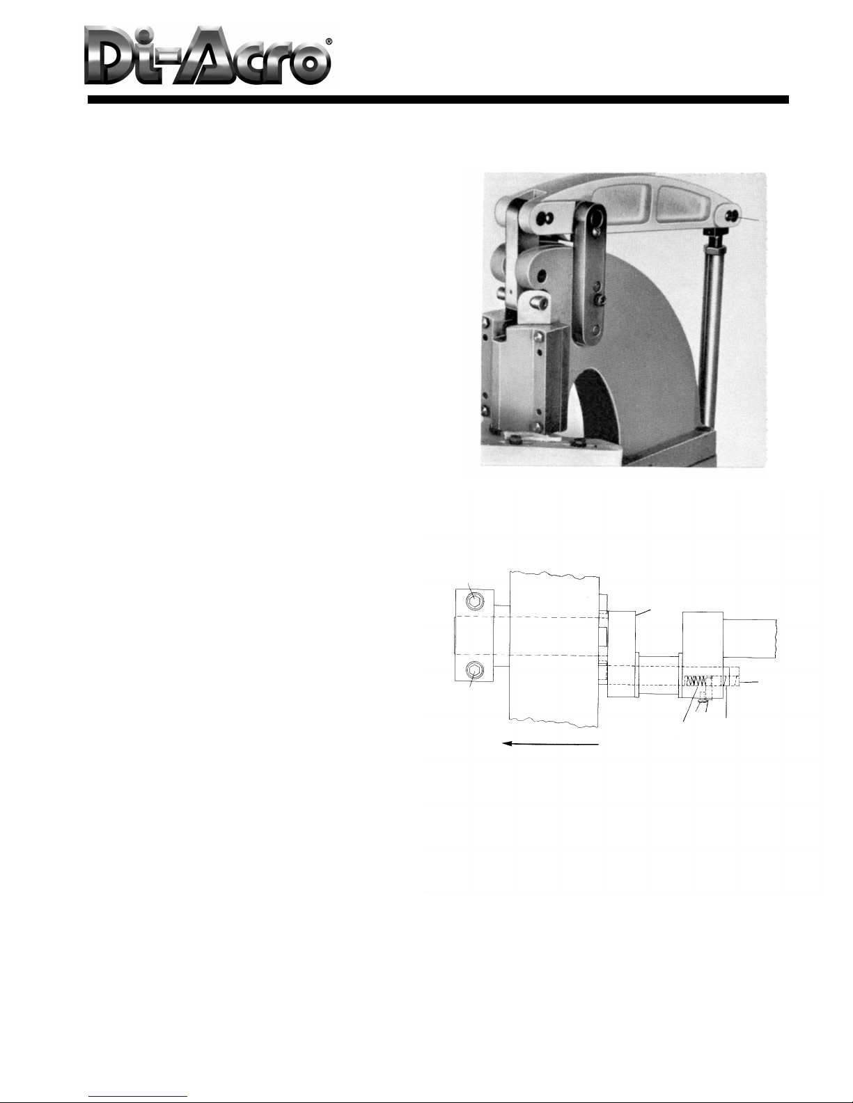
D. Setting depth of stroke
With power o , step on oot pedal and turn
lywheel by hand until ram is at bottom o
stroke.
Remove pin (N) and loosen lock nut (O)
Lower ram by hand until upper blade is 1/16”
below edge o lower blade.
Adjust connecting rod link on sha t until pin (N)
will re-enter hole. Re-tighten lock nut (O).
1.
2.
3.
4.
SETUP
B
D
A
H
B
CA
G
E
N
O
3
Lower unit o Notcher is equipped with oilite bronze
bearing requiring occasional lubrication at points
indicated in photos. (Rocker arm not shown)
Upper unit should be oiled daily at points indicated.
Clutch linkage - oil occasionally.
MAINTENANCE
A. Sharpening blades
Blades are dual edged. A new cutting edge is
obtained by changing right blade to le t side and
visa versa.
I only a slight amount o sharpening is required,
grind wide edge only, as this will eliminate neces-
sity o resetting clearance.
When grinding ends be sure to maintain angle
presently on blade.
Reset scale to zero, lining up zero on scale with
straight edge along blade cutting edge
1.
2.
3.
4.
B. Adjusting blade clearance
Remove table.
Loosen blade mounting bolts A and B.
Loosen blade carrier bolts J.
Adjust lower blades to required tab (per
instructions, A-1, 2, 3, under SETUP).
Set upper blades for no tab or a tab smaller
than set in lower blades.
Back off screws K and pull blade carrier
away from top blade.
Move ram to bottom of stroke.
Turn in screws K by hand pushing blade in
until it contacts upper blade. Placing a shim
or piece of paper between blades will pro-
vide clearance to prevent rubbing of
blades. Too much clearance will cause burr
on workpiece. Excessive rubbing of blade
will reduce blade life.
Tigten bolts J.
Set upper blade to tab notch in lower blade
and tighten.
1.
2.
3.
4.
5.
6.
7.
8.
9.
10.
C. Adjusting ram clearanceC. Adjusting ram clearance
C. Adjusting ram clearanceC. Adjusting ram clearance
C. Adjusting ram clearance
Remove ram cap M and remove a shim from
both sides. Color of shim indicates the
thickness: Purple .0015; Red .002; Green .003;
Blue .005.
Replace cap.
1.
2.
UBRICATION
1.
2.
3.
MAINTENANCE
B
A
J
K
M
BAJ
2 Places
2 Places
Other Side
2 Places
4
Remedy: Rotate lywheel by hand to
bottom o stroke: Remove brake collar
and brake assembly. Remove screw R
and pin S. Pull out clutch dog. Remove
burrs particles. Replace spring is weak
or broken. (To replace clutch dog
remove bolts T and slide lywheel in
direction indicated by arrow. Insert
clutch dog and pin S. Tighten screw R.
Slide lywheel back into place and re-
tighten bolts T.)
TROUB E SHOOTING
Problem: Double tripping, or not stopping at
end o single cycle.
Cause: Brake too loose, causing dog to
coast on by release lever.
Remedy: Tighten brake adjustment.
Cause: Brake too tight, or ram binding,
causing release lever to slip by instead o
pulling clutch dog.
Remedy: Loosen brake, or remove pin
N and check or binding in ram. I
binding remove cap and remove burrs
and polish ram until it is operating
reely.
Problem: Machine will not operate when pedal
is depressed.
Cause: Clutch dog binding, or broken
spring.
TROUBLE SHOOTING
5
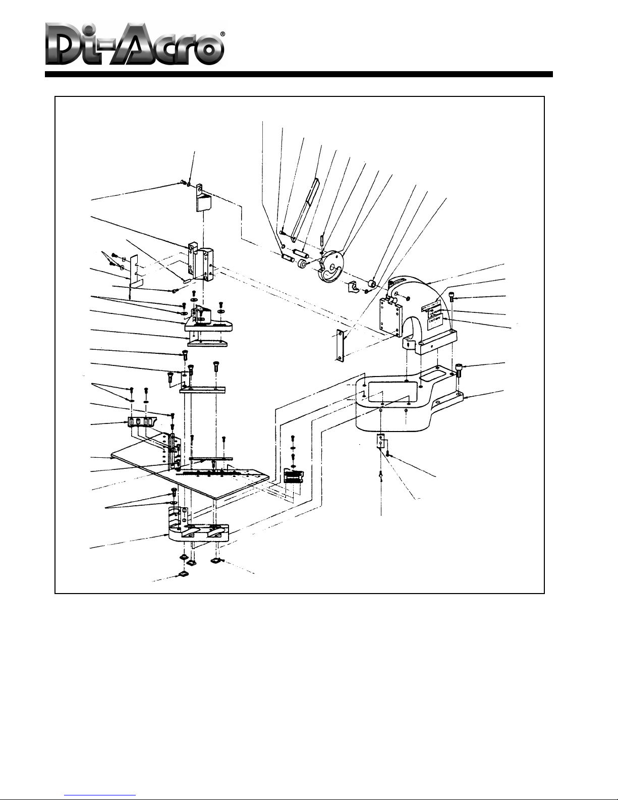
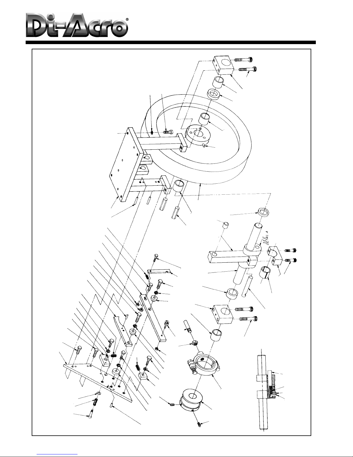
HEAD ASSEBLY
26 25 27
28
25 29 30 31 32 33 34 25
35, 36, 37, 38
39
43, 42
40
44, 43
45
46
47
49, 51
50
48
52
1
2
3, 4
5
6
7
8
9
10, 11
13
14
16, 17
18
19
20, 21
22
23
24
6
15
12

ITEM DESCRIPTION QTYPART NUMBER
1
2
3
4
5
6
7
8
9
10
11
12
13
14
15
16
17
18
19
20
21
22
23
24
25
26
27
28
29
30
31
32
33
34
35
36
37
38
39
40
41
42
43
44
45
46
47
48
49
50
51
52
T-NUT
BLADE CARRIER
HEX HEAD CAP SCREW
FLAT WASHER
RULE
FLAT HEAD SOCKET CAP SCREW
TABLE
PROTRACTOR GAUGE
BINDER MACHINE SCREW
FILLISTER HEAD MACH SCREW
FLAT HEAD WASHER
LOWER BLADE
FLAT HEAD SOCKET CAP SCREW
UPPER BLADE
RAM ASSEMBLY
HEX HEAD CAP SCREW
FLAT WASHER
SOCKET HEAD CAP SCREW
GUARD ASSEMBLY
HEX HEAD CAP SCREW
FLAT WASHER
SPRING PIN
CAP
DRIVE FITTING
RETAINER RING
CAM ROLLER PIN
BUTTON HEAD SOCKET CAP SCREW
LONG HANDLE ARM
CAM PIN
SQUARE HEAD SET SCREW
JAM NUT
ROLLER
CAM
BEARING
SHIM
SHIM
SHIM
SHIM
UPPER CASTING
SOCKET HEAD CAP SCREW
SOCKET HEAD CAP SCREW
INSTRUCTION PLATE
DRIVE SCREW ROUND HEAD
NAME PLATE
CAUTION PLATE
HEX HEAD CAP SCREW
BASE
HEX HEAD CAP SCREW
JAM NUT
BACKUP PLATE
HEX HEAD CAP SCREW
SPRING PIN
8905350-000
8031110-101
21A0308C1102
61X0308C1332
8031160-101
20C0104F0102
8000110-501
8031140-571
22FXX060108
20A0104F0508
51X0104
8031120-901
20C0516C2000
8031120-900
8031121-300
21A0516C1102
61X0516
20A0516C1102
8031110-609
21A0516C0102
61X0308-0104
0012220-000
8040110-800
8690100-200
8470510-100
8060120-300
20B0516C0508
8030120-800
8030120-302
23C0516C2000
31X0516C
8156111-300
8030120-200
8310410-100
8030570-101
8930570-101
8940570-101
8030570-102
8040110-200
20A0102C1304
20A0516C1102
8030650-310
29AXXX0X0108C
031-6501110
8030650-300
21A0102C1304
8031110-100
21A0308C1000
31X0102C
031-1105011
21A0308C1104
8120313-600
4
1
4
4
2
3
1
2
4
4
4
2
4
2
1
4
4
4
1
4
4
4
1
1
4
1
1
1
1
1
1
1
1
1
2
2
1
1
1
4
1
1
4
1
1
4
1
4
4
4
4
4
HEAD ASSEMBLY
7

LOWER ASSEMBLY
30
31
34
27
22
15
21
20
19
16
15
14
1312
11
10
3, 4
1, 2, 3, 4
2
35, 36, 37
5
67
8
9
32
16
17
18
23
24
25, 28
29
33
8

Qty
1
1
1
1
1
1
1
1
1
2
1
1
2
2
4
4
4
1
2
2
1
1
1
1
1
10
1
1
1
1
3
2
1
1
4
Description
Foot Pedal
Hex Head Cap Screw
Lock Washer
Jam Nut
Foot Pedal Link Block
Pedal Arm
Hex Head Cap Screw
Spring Pin
Spring
Truss Head Mach Screw
Pedal Bkt Wldmt
Jam Nut
Flat Washer
Jam Nut
Hex Head Cap Screw
Flat Washer
Hex Head Cap Screw
Sheave
Motor Mount Clamp
Motor Mount
V-Belt
Name Plate
Warning Plate
Name Plate
Arrow Plate
Drive Screw
Chute Assy
Guard
Cabinet
Foot Pedal Link Rod
Flat Head Mach Screw
Panel Screw
Rubber Extension
Foot Pedal Guard
Socket Head Cap Screw
Part No.
035-1308003
21A0516C1104
62X0516M
31X0516C
250-1301064
035-1325033
21A0308C1104
1203135
5102103
22D0104C0508
035-1301100
31X0308C
61X0104
31X0104C
21A0516C3000
4901106
21A0516C0508
1205089
035-1110080
035-1110079
4401001
068-6502001
035-6503001
032-6501113
032-6503018
29AXXX0X0108C
035-1109701
032-1106003
032-1109001
032-1301056
22C0104C0508
4701147
6999922
035-1106022
20AXX10C0308
Item
No.
1
2
3
4
5
6
7
8
9
10
11
12
13
14
15
16
17
19
20
21
22
23
24
26
27
28
29
30
31
32
33
34
35
36
37
LOWER ASSEMBLY
9
DRIVE GP
51
50
40
30
29
49
29
48
47
29
46
34
52
33
32
31
See
Detail A
33
45
41
40
30
29 36
35
13
8
25
28
27
26
15
8
25
9
8
24
23
9
8
22
21
23 38
39
41
42
43
44
Detail A
123
455678910
11 12 13 14 15 16 1718 19 20
10

Qty
Used
1
1
1
1
2
1
1
5
3
1
1
1
2
1
2
1
1
1
2
1
1
1
2
1
2
1
1
1
4
2
1
1
1
1
1
1
1
1
1
4
1
1
1
1
1
3
1
1
1
4
4
1
Description
Shoulder Screw
Spring
Flat Washer
Trip Mount
Hex Head Cap Screw
Spring Container
Spring Pin
Lock Washer
Hex Head Cap Screw
Spring
Clutch Release Lever
Dowel Pin
Hex Head Cap Screw
Jam Nut
Jam Nut
Trip Lever
Spring Bolt
Spring
Dowel Pin
Cranksha t Support
Dowel Pin
Spacer
Socket Set Screw
Spring Container
Link Spacer Sleeve
Hex Nut
Foot Pedal Pivot Stud
Brake Rod
Bearing
Cranksha t Bearing Block
Cranksha t Trip Spacer
Cranksha t
Connecting Arm Assy
Clutch Spring
Sa ety Link
Hex Head Cap Screw
Spring
Brake Collar
Brake Show Assy
Socket Head Cap Screw
Clutch Dog
Spring
Binder Head Mach Screw
Clutch Dog Pin
Bearing Insert
Drive Pin
Flywheel
Oil Hole Cover
Flywheel Spacer
Hex Head Cap Screw
Flat Washer
Bearing
Part No.
25X0516C1104
5102101
61X0104
035-1110090
21A0516C1000
035-1301091
1203134
62X0508
21A0308C1000
5102102
035-1301096
1203105
21A0308C1104
31X0308C
31X0104C
035-1301095
035-1301097
120-5102022
1203178
035-1110065
1203192
035-1301092
23A0516C1000
035-1206083
250-1108069
30X0102F
250-1301062
056-1207056
3104104
035-1110067
035-1201069
035-1201060
035-1201702
035-1206085
035-1301094
21A0104C1000H
5102103
270-1207054
270-1207710
20A0308C3000
035-1206089
035-5102082
22FXX06C0104
035-1203066
035-3106055
035-1206084
035-1204086
411001
035-1201087
21A0308C1104
4901159
3104101
Item
No.
1
2
3
4
5
6
7
8
9
0
11
12
13
14
15
16
17
18
19
20
21
22
2
24
25
26
27
28
29
30
31
32
33
34
35
36
37
38
39
40
41
42
43
44
45
46
47
48
49
50
51
52
DRIVE GP
11
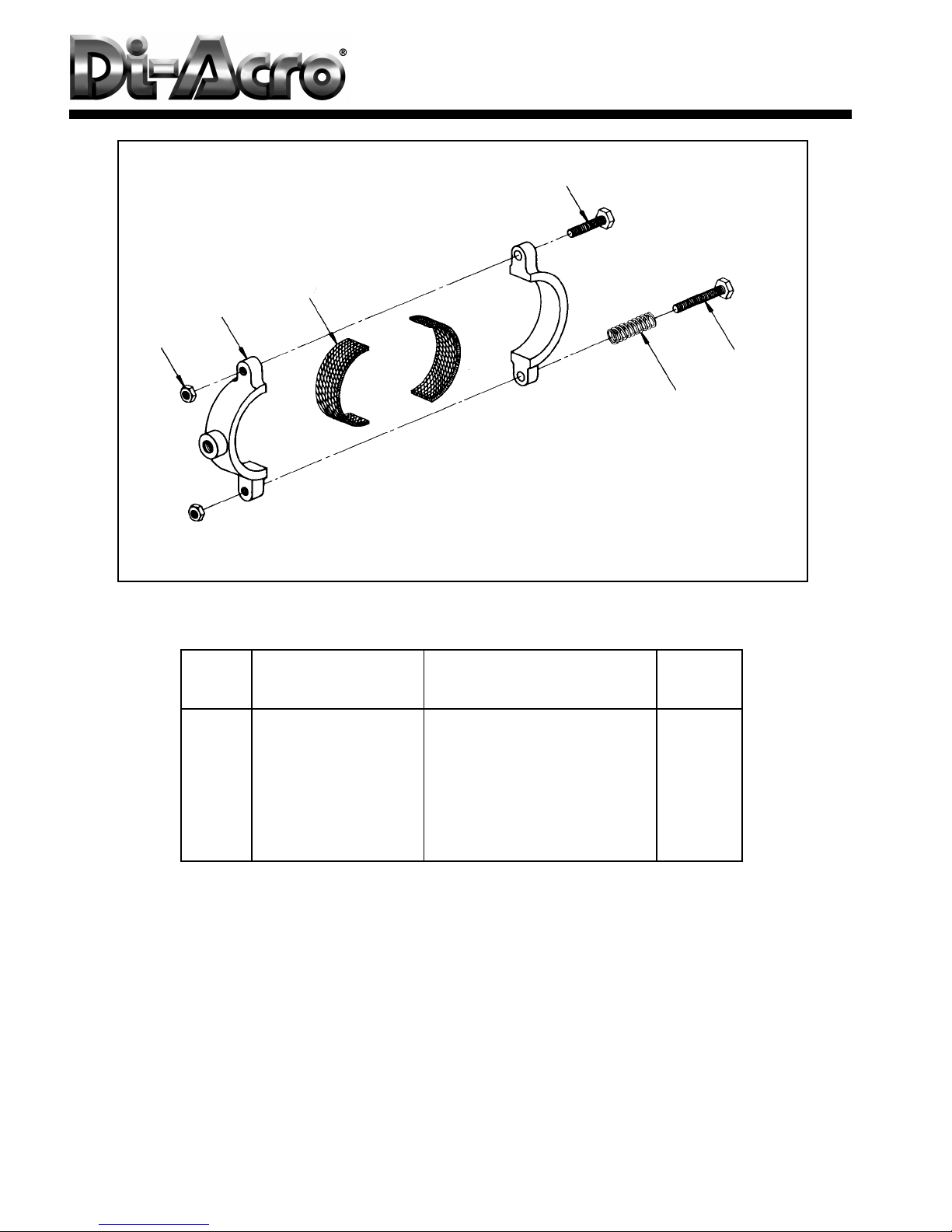
Item
No.
1
2
3
4
5
6
Qty
Used
2
1
2
1
1
1
Description
Jam Nut
Brake Shoe
Brake Lining
Hex Head Cap Screw
Hex Head Cap Screw
Spring
Part No.
31X0516C
270-1207055
270-1207001
4701137
4701112
512110
NOTE:
CEMENT LINING 3 TO SHOE 2 WITH
3M NO. 1838 SCOTCH WELD ADHESIVE
BRAKE SHOE ASSEMBLY
1
2
3
4
5
6
12

Sym
2PB
2PB
2PB
1PB
1PB
1PB
1LT
1LT
1LT
4FU
1T
10L
1M
1-3FU
1-3FU
DISC
Qty
1
3
1
1
1
1
1
1
1
1
1
1
1
1
3
1
3
1
1
1
Description
Operating Mechanism ~ GE #343L543G3
Terminal Block ~ Curtis #2PSWTC
Track ~ Curtis SW-96 (5” Length)
Legend Plate Start Furnas #D11804003
Contact Block NO ~ Furnas #BJK
Pushbutton Operator ~ Furnas #BJP2
Legend Plate - Stop - Furnas #D11804004
Contact Block NC ~ Furnas BJJ
Push Button Operator ~ Furnas BJR2
Legend Plate - On - Furnas D11804013
Amber Lens ~ Furnas BJ4G
Pilot Light ~ Furnas BJL1
Fuse ~ Buss FNM1/2
Trans ormer Micron BX150MBRTW13-XK
Heater Element ~ Furnas #H-15
Starter ~ Furnas 14CF32AA
Fuse Buss #FRS 1-6/10
Fuse Clip ~ GE THMC 3100
Disconnect Switch ~ GE THMS 31 Model 2
Enclosure Panel
Part
No.
3308115
065-3308001
3332017
3303088
3303058
3332089
3303089
3303059
3332015
3303050
3302013
3318051
3311043
3323018
3318014
SEQUENCE OF OPERATION
PRESS “START” PUSHBUTTON “2PB”. “ON” LAMP “1LT” AND
ELECTRIC MOTOR “1MTR” ARE ENERGIZED.
PRESS “STOP” PUSHBUTTON “1PB”. “ON” LAMP “1LT” AND
ELECTRIC MOTOR “1MTR” ARE DE-ENERGIZED
ELECTRIC DIAGRAM
L1
L2
L3
1FU
2FU
3FU
GND FUSES, IF
FUSED
1M 1OL 1T1
1T2
1T3
1MRT
ELECTRIC MOTOR
1425 RPM - 1/2 HP
FRAME 56
4FU
115V - 50HZ
1
2
3
1M
1PB
STOP
2PB
START
1M
A
1LT
ON
1OL
ELECTRIC MTR - 3
TO BE GROUNDED BY USER
IF CONDITIONS PERMIT
A
START
STOP
1PB
DISC
1FU 2FU 3FU
IF FUSED
1T
X2
1
23
4FU
1M
10L
1T1 1T2 1T3
13

Sym
1MTR
1M
1M
DISC
Qty
1
1
1
1
Description
Motor
Manual Starter Furnas
Manual Starter Furnas
Disconnect Switch
Part No.
3301020
3304043
3304042
3331013
ELECTRIC DIAGRAM
1MRT
1M
R
DISC
115/230V
50/60 HZ
14
Table of contents
Popular Lathe manuals by other brands


Central Machinery
Central Machinery 93212 quick start guide

MetalMaster
MetalMaster HG3208VR manual

ATEK MAKINA
ATEK MAKINA JUMBO DOUBLE Instruction booklet

Holzstar
Holzstar DB 1202 Vario instruction manual

HENNESSY INDUSTRIES
HENNESSY INDUSTRIES Ammco 800 Safety Instructions, Installation Instructions, Operating Instructions, Maintenance Instructions

Baileigh
Baileigh TN-250 Operator's manual


