STEININGER ROCK.AIR User manual
1
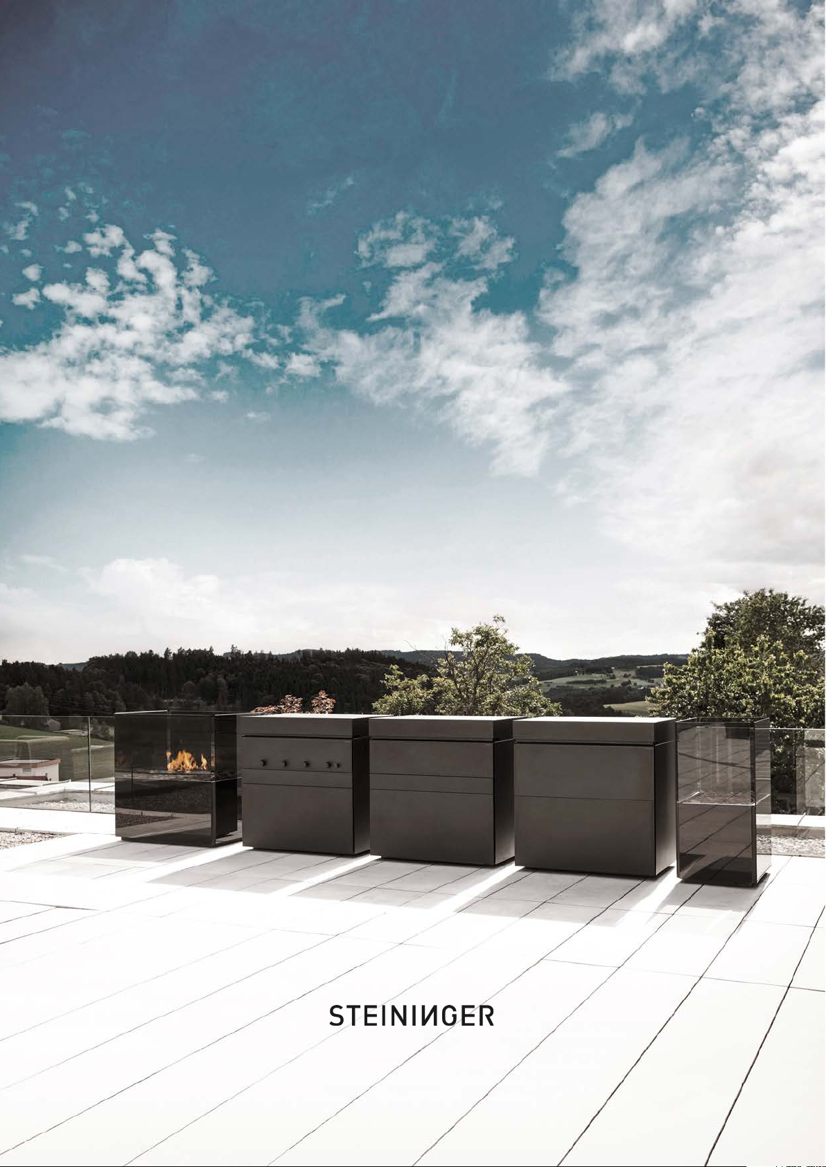
ROCK.AIR
OUTDOOR KITCHEN
USER MANUAL
Showrooms: Sankt Martin .Linz .Vienna (A) .Hamburg (D) .London (GB) .St. Gallen (CH)
KITCHEN INTERIOR DESIGN ARCHITECTURE
www.steiningerdesigners.com

2
CONTENTS
SAFETY INSTRUCTIONS p. 3
INSTALLATION INSTRUCTIONS p. 4
PLANNING INSTRUCTIONS p. 6
ROCK.AIR.FIRE p. 7
ROCK.AIR.WASH p. 10
ROCK.AIR.COOL p. 14
ROCK.AIR.COOK p. 18
CLEANING AND CARE p. 24
WINTERIZATION & DEWINTERIZATION p. 25

3
SAFETY INSTRUCTIONS
• Please read this user manual and the safety instructions carefully.
• The unit may only be connected to the gas line by a specialist.
• For units operated using natural gas, the connection must always be carried out
in coordination with the local gas works.
• When connecting the gas, care must be taken to ensure that the main gas shut-off valve is
easily accessible and that the gas pressure reducer is installed close to the unit and in an
easily accessible position, as specified on the type plate.
• For propane gas units, the connection to the gas supply must be carried out by an expert
and approved by an expert with the requisite authorisation.
• In propane gas systems, only gas regulators marked “50 mbar” are permitted for
installation in the supply line between the gas canisters and the unit itself.
• The use of regulators with adjustable operating pressure or high-pressure regulators is
strictly prohibited.
• Propane gas systems must be secured with sheet cladding to prevent access by
unauthorised persons.
• Always check the unit and the gas supply system for leaks after moving them.
• Gas canisters or tanks weighing more than 14 kg must not be kept indoors or close to the
unit.
• The unit may only be converted to a different type of gas by a specialist.
• Units that carry water must be protected against frost.

4
INSTALLATION INSTRUCTIONS

5
MODEL ITEM ELECTRIC WEIGHT
Gas connection Ø Nozzles Ø Gas connection Ø Nozzles Ø
Rock.Air Cook electric sm-ro-air-cook-el 400 V / 9 KW 250 Kg - - - - - - - -
Rock.Air Cook gas sm-ro-air-cook-gas 250 Kg 1/2" 1.6mm 15mm 0.97mm - -
Rock.Air.Fire Gas small sm-ro-air-fire-gs 240 VAC / 16A 150 Kg - - - -
Rock.Air.Fire Gas tall sm-ro-air-fire-gt 240 VAC / 16A 200 Kg - - - -
Rock.Air.Wash sm-ro-air-wash - 200 Kg - - - - 1/2" 1/2" 50mm -
Rock.Air.Wash + FP sm-ro-air-wash-fp 240 VAC / 16A 250 Kg - - - - 3/4" - 38mm 19mm
Rock.Air.Cool FP sm-ro-air-cool-fp 240 VAC / 16A 200 Kg - - - - - - - -
Rock.Air.Cool SZ sm-ro-air-cool-sz 240 VAC / 16A 240 Kg - - - - - - - -
Rock.Air Freeze SZ sm-ro-air-freeze-szi 240 VAC / 16A 250 Kg - - - - 3/8" - - -
Gas connection acc. To DIN EN 3383
GAS WATER
1/2" DIN EN 3383 1/2" DIN EN 3383
1/2" DIN EN 3383 1/2" DIN EN 3383
Water supply Ø Water drain Ø
Cold Hot
Direct drainage
connection
Connection on
siphon (for GS)
Domestic gas line
Natural gas 20mbar
Gas canister
Propane 50mbar
INSTALLATION INSTRUCTIONS
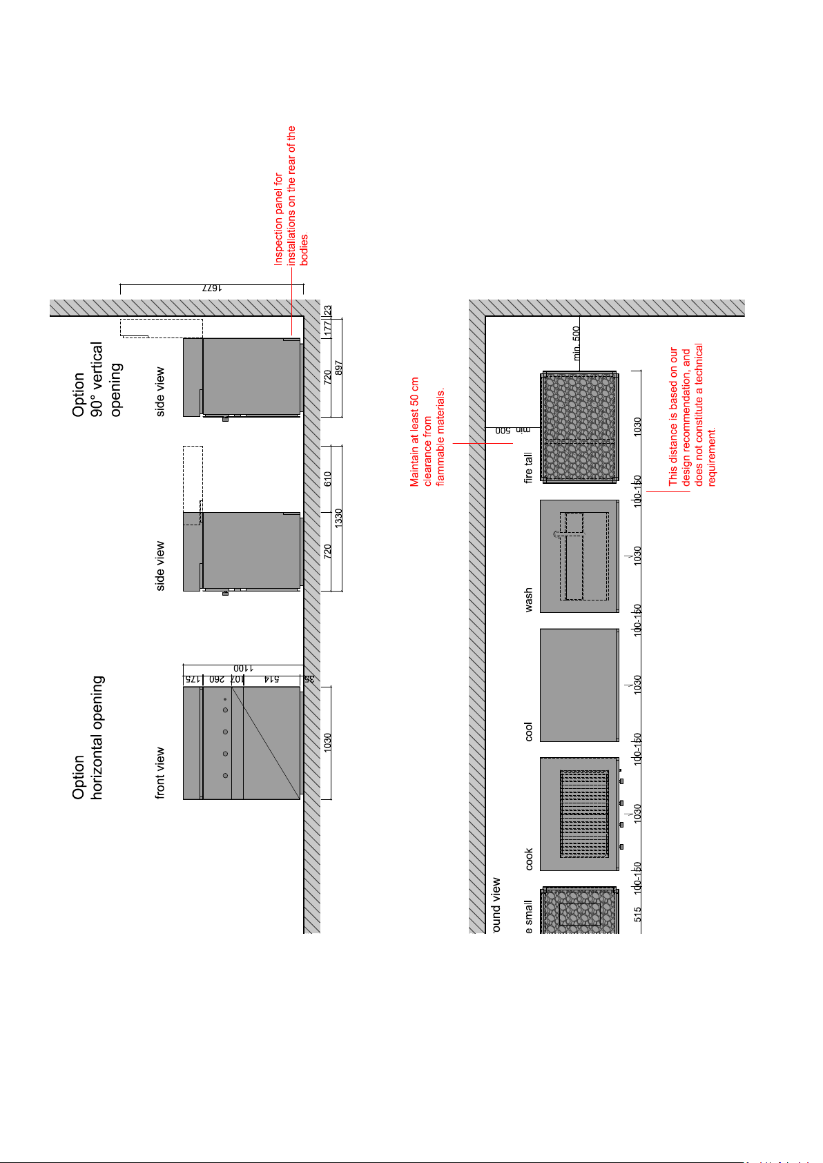
6
PLANNING INSTRUCTIONS
• When setting up the individual cubes, make sure that the load points are positioned on a solid base.
• The tools supplied with the unit can be used to adjust the height of the feet and level the cubes. Level
the bodies carefully.

7
ROCK.AIR.FIRE
A Glass front
To open, lift up and pull away
towards your body.
D Infra-red receiver for remote control
Hold the remote control close to the sensor
to turn the flame on/off.
C Gas canisters
Turn open before operation and turn closed
afterwards.
Available items • sm-ro-air-fire-bs ...
• sm-ro-air-fire-bt ...
• sm-ro-air-fire-gs ...
• sm-ro-air-fire-gt ...
B Lava rock/gas ignition
Do not place lava rocks in front of the gas ignition.
• POWER ON Press buttons 1 and 10 successi-
vely within 2 seconds. The ignition sequence
is initiated. First, the pilot burner starts to
ignite (ticking sound). As soon as the pilot
flame burns stably, the main burner also ig-
nites (also audible). The gas fire burns at the
factory-preset level.
• POWER OFF Press button 1 for at least 3
seconds. The gas supply is interrupted imme-
diately. The remaining gas that is still inside
the gas fire burns completely. The gas fire
extinguishes.
• FLAMES HEIGHER
• Press button 5 once, several times or conti-
nuously until the desired flame height is rea-
ched. If the button is pressed for longer than
30 seconds, or if the maximum flame height
is reached, an acoustic signal is emitted.
Model Item Gas Pressure Connection Gas consumption
ROCK.AIR Fire Gas Tall sm-ro-air-fire-gt Natural gas 20 n.s.
ROCK.AIR Fire Gas Tall sm-ro-air-fire-gt Liquid gas 50 3-5 kg/h
ROCK.AIR Fire Gas Small sm-ro-air-fire-gs Natural gas 20 1,42 m³/h
ROCK.AIR Fire Gas Small sm-ro-air-fire-gs Liquid gas 50 1,17 kg/h
• FLAMES LOWER
Press button 9 once, several times or conti-
nuously until the desired flame height is rea-
ched. If the button is pressed for longer than
30 seconds, or if the minimum flame height is
reached, an acoustic signal is emitted.
• MODULATING FLAMES AUTOMATICALLY
Press button B (3) once. This is confirmed by a
single acknowledgement tone. The flames are
periodically enlarged and reduced.
• DEBUGGING / RESET
In the event of a fault, the gas fire switches off
for safety reasons. Before it can be restarted,
the control unit must be reset. Press button C.
If the fault occurs again, consult a specialist.
Power off 1
Power on:
Press 1 and 10 successively
within 2 sec
Debugging 4
Flame higher 5
Flame smaller 9
Fire noise generator (opt.) higher 8
Round button 10
Fire noise generator optional 2
Fire noise generator (opt.) lower 6
Automatic flame
modulation / Eco-
wave 3

8
ROCK.AIR.FIRE
Removing the glass front A for gas inspection:
• Take the glass front in both hands.
• Lift upwards.
• Pull it away towards your body.
Mounting the glass front A
• Take the glass front in both hands
and hang it on the hooks (two on
each side, top and bottom) from above.
Connecting the gas canister:
• Connect the connection hose on the gas canister C
to the fireplace and turn the locking mechanism until
the green symbol appears.
Keep lava rocks away from the gas ignition B , other-
wise the unit may not ignite.
The infra-red receiver D for the remote control must
be kept clear.
C
B
D
Warnings:
• Never leave the open fire burning unattended.
• Never throw flammable materials (cigarette stubs, wood, etc.) or other waste into the fire.
• Never allow the burner’s electrical system to come into contact with water.
• It is prohibited to re-ignite the burner immediately after it has been turned off. Please wait approx. 10
minutes to ensure that all the parts have stopped glowing.
• If you smell gas: Immediately close the gas supply using the connection fitting on the unit. Extinguish
all ignition sources immediately (e.g. burning candles, cigarettes, cigars, pipes). Do not press any
electrical switches. Do not use any telephones (mobile or landline). Notify the installation company.
9
ROCK.AIR.FIRE
ATTENTION
The ROCK.AIR fireplaces may only be heated or fired with the fuels intended for them (= burning gel or
gas). These are only suitable for outdoor use.
• Lighting a fire in any other way (with wood, coal or other combustible materials) is strictly prohibited!
• Furthermore, burning or introducing highly flammable or explosive substances into the ROCK.AIR
fireplaces as well as their storage in the immediate vicinity of the ROCK.AIR fireplaces is also strictly
prohibited due to the risk of explosion!
• Use the ROCK.AIR fireplaces only as described in this manual. Any use other than specified may result
in material damages or even personal injuries. Steininger does not assume any liability for damages
caused by improper use
BURNING GEL
• Spread the burning gel in the metal tray provided, so that the bottom is covered.
Steininger recommends „BLOMUS Burning Gel 1000 ml“.
• Fill in the desired amount depending on the desired burning time
1000 ml are enough for about 40 minutes
• The flame must not be covered or extinguished. The fire must extinguish without intervention.
• Refilling is only allowed in a cooled down state.
POWER CONNECTION
A 230 VAC/16A socket must be provided for the power connection. The connection must be made via
a separate main switch in order to be able to switch off the gas fire in an emergency (e.g. if IR remote
control fails).
The burner is phase sensitive. If the burner beeps continuously -> unplug it, turn it 180° and
plug it back in.
When positioning the socket, please take into account that the connection cable ( I I ) has a
length of 1,200 mm.
If the power cable of this appliance is damaged, it must be replaced by the manufacturer or
their service agent or a similarly qualified person in order to avoid hazards.
10
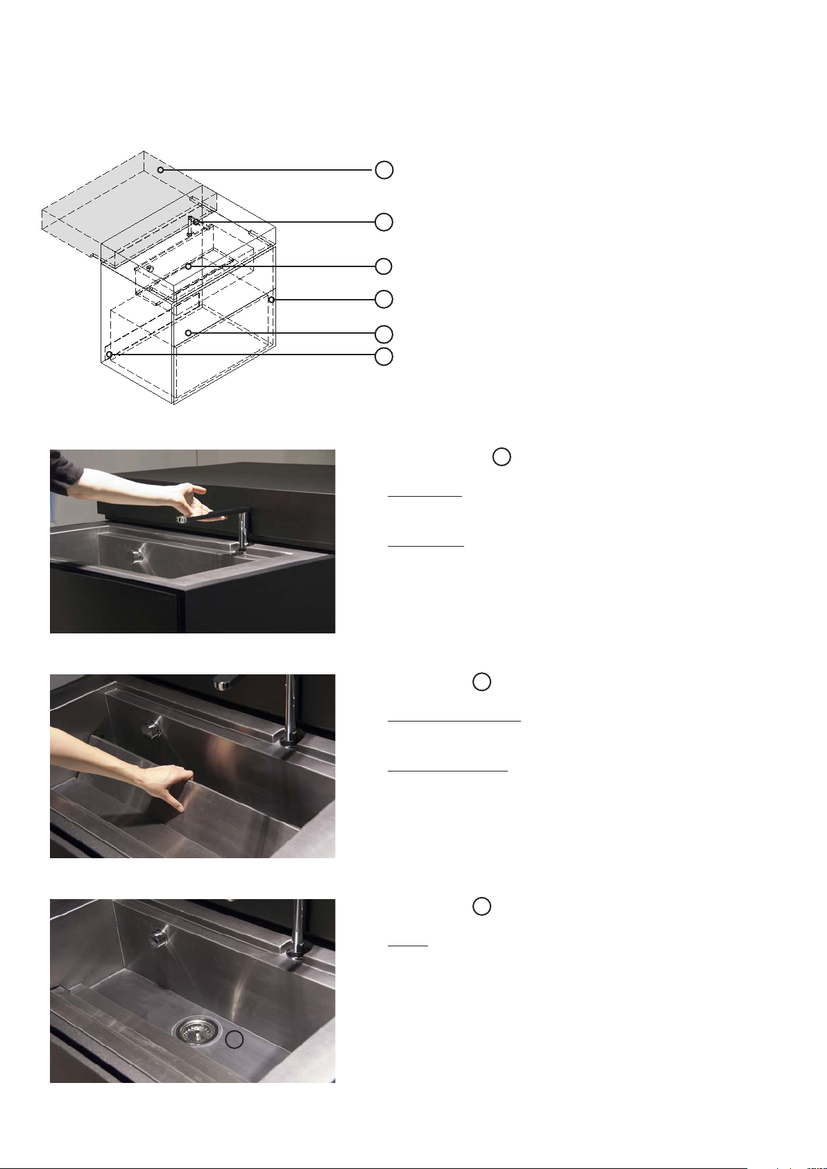
ROCK.AIR.WASH
Extendible tap B
Extending:
• Pull the tap upwards.
Retracting:
• Press down firmly on the top of the water outlet.
Drain cover C
Opening the drain:
• Pull the drain cover off from above.
Sealing the drain:
• Re-insert the cover, starting with the edge closest to
your body.
Sieve cover C
Drain:
• Pull up - open
• Press in - closed
A Cover
To open, lift up and slide back.
E Siphon (rear)
D Drawer: To open, pull out at left or right side.
Gas canister and replacement utensils in drawer.
Available items • sm-ro-air-wash ...
• sm-ro-air-wash-fp ...
C Drain cover and, below, sieve cover.
B Extendible tap
F Inspection flap (rear)
C
11
C Drain cover and, below, sieve cover.
Siphon E
Removal:
• Drain the siphon before winter (to prevent frost).
• Open the inspection flap.
• Unscrew the white, S-shaped pipe (siphon) by turning
it right and left.
• If the dishwasher has been removed, drain the siphon
from the front of the unit.
• Remove the siphon and drain it.
• The line and supply line must be kept free of water
during winter.
• If necessary, use compressed air to drain the supply
line thoroughly.
Installation:
• Screw the drained siphon back on tightly.
• Close the inspection flap.
ROCK.AIR.WASH
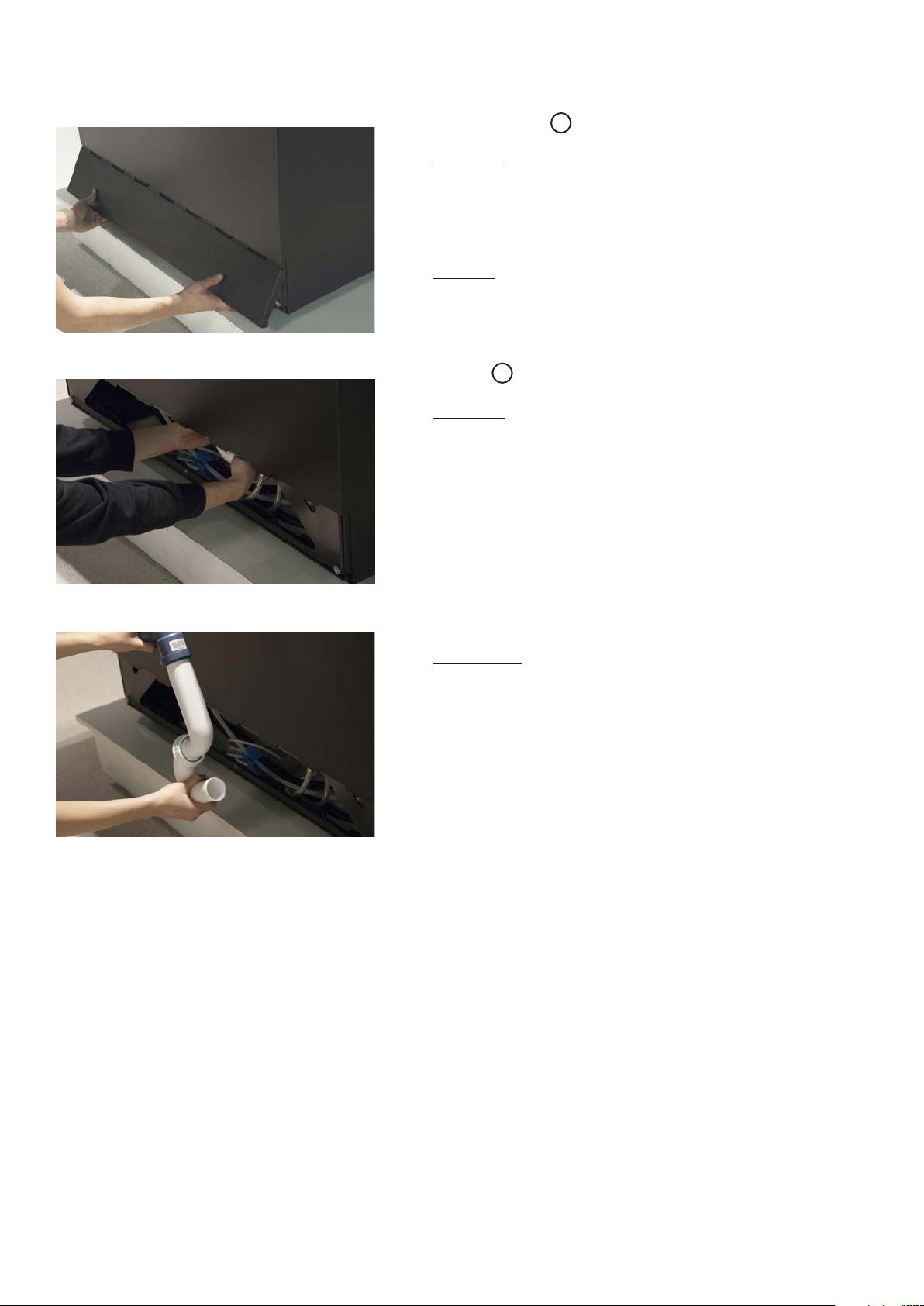
Inspection flap F
Opening:
• To open the inspection flap, grip it at the bottom.
• Gently press it upwards.
• Pull towards your body.
• Pull down and remove.
Closing:
• Insert the top section of the inspection flap in the
toothed rail.
• Slide it up and press it against the cube.

12
ROCK.AIR.WASH
• Hold the front plate in one hand, and use the oth-
er hand to pull out the plastic retaining pin. (Do not
twist.)
• Detach the front plate from the unit (pull downward
and away): Pull 3cm towards your body and lower a
little. Hold the front plate in place.
• Pay attention to the cables.
• Disconnect the cables.
• The front plate must be held in place while the cables
are being detached.
• Carefully detach the green and green/yellow cables
on the side of the drawer.
Removing the dishwasher:
• Grip the dishwasher on the left and right-hand sides.
• Apply a little pressure to detach it from the front
(magnet).
Available items • sm-ro-air-wash
• sm-ro-air-wash-fp

13
ROCK.AIR.WASH
Removing the drawer D
• Remove all 5 screws on both sides (see photo).
• Do not drop the screws into the rail.
• Pull the drawer to the front and away.
• Open the inspection flap F on the rear of the unit
and disconnect the power supply and the water sup-
ply and drain lines.
• Pull the dishwasher out carefully.
• In case of frost, make sure that all parts that carry
water are drained.
Removing the dishwasher:
• Blue cable: Pull the clip on the white plug forwards,
then pull the plug upwards to unplug it.
• Remove the front plate.
• Undo the fixing screws on the underside of the unit,
on both sides.

14
ROCK.AIR.COOL
D Inspection flap (rear)
Inspection flap D
Opening:
• To open the inspection flap, grip it at the bottom.
• Gently press it upwards.
• Pull towards your body.
• Pull down and remove.
• Disconnect the power, the water and the supply line.
Closing:
• Insert the top section of the inspection flap in the
toothed rail (see photo).
• Slide it up and press it against the cube.
Removing the cooler:
• Remove the worktop B using a glass suction
device.
• Undo the round-head screws in the front profile rail.
• Remove the profile rail.
• Remove the countersunk screws from the front cross-
strut.
• Remove the cross-strut.
B Worktop
A Cover
To open, lift up and slide back.
Available items • sm-ro-air-cool-fp ...
• sm-ro-air-cool-sz ...
• sm-ro-air-freeze-szi ...
C Refrigerator drawer
To open, pull out at left or right side.

15
ROCK.AIR.COOL
Removing the cooler:
• Remove the magnetic panels from both sides of the
unit.
• Using your finger, pull the rail towards your body.
• Remove one screw on each side from the inside of the
unit.
• Grip the cooler in both hands and apply a little pres-
sure to detach it from the drawer (magnet).
Removing the drawer:
• Remove the screws on both sides (see photo).
• Do not drop the screws into the rail.
• Pull the drawer to the front and away.

16
ROCK.AIR.COOL
Removing the cooler:
• Push the unit back (into the body) to allow access to
the screws.
• Undo 7 screws each on the left and right-hand sides
of the frame.
• Remove the frame.
• Carefully pull the unit out and lift it towards the front
(ideally with 2 people).
Installing the cooler:
• When installing the cooler, open the inspection flap
and carefully pull on the hoses to prevent them from
becoming kinked.
• When installing the frame, make sure that the pins for
the side frame panel are in the correct holes. Once
you have done this, insert and tighten the screws.
(Caution: The screws have several different lengths.)
• Carefully pull the unit out and lift it towards the front
(min. 2 people).
17
ROCK.AIR.COOK
• ALWAYS keep the hood open when grilling.
• Gentle cooking with the hood closed is permitted up to temperatures of 200°C.
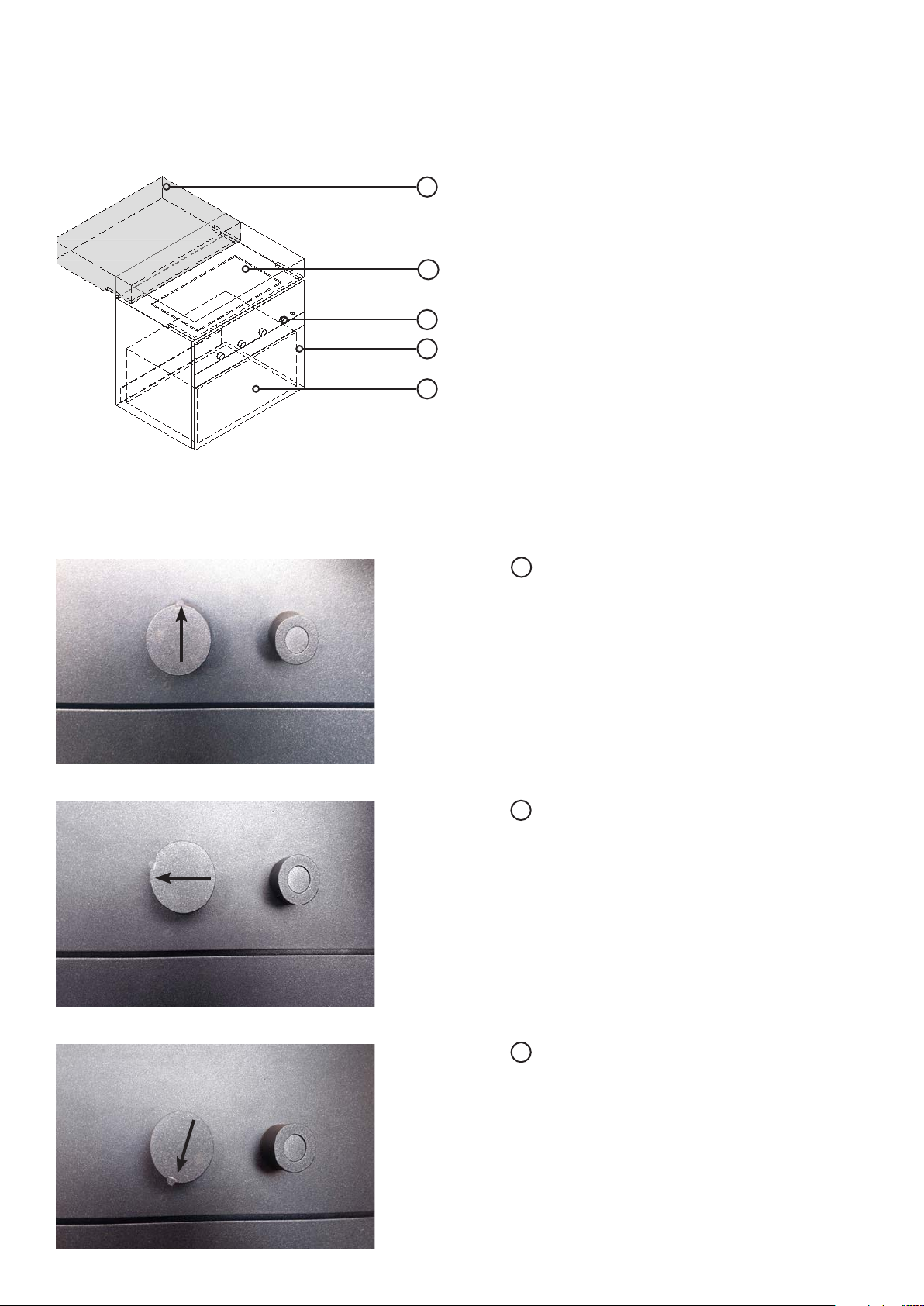
Gas knob C : Off
Gas knob C : Max. flame
Gas knob C : Min. flame
A Cover
To open, lift up and slide back.
B Grill surface
C Gas knob
D Drawer
To open, pull out at left or right side.
E Gas canister (in the drawer).
Available items • sm-ro-air-cook-gas ...
• sm-ro-air-cook-el ...
• sm-ro-air-cook-opt ...

18
ROCK.AIR.COOK
Connection values in acc. with CE Germany
Starting operation:
Fill the bottom grease tray with water.
Open the main gas valve and the gas canister (E).
Set the knob to “HIGH” and press it.
At the same time, press the electric ignition.
Propane 50mbar Natural gas LL 20mbar Natural gas H+E 20mbar Propane 28-30/37 mbar, 29 mbar
1,2 kg/h 1,88 m 1,60 m 1,20 kg/h
121
2

19
ROCK.AIR.COOK
Replacing the battery (AA) in the electric ignition:
Turn the electric ignition to the left.
(If you do not hear a ‘clicking’ sound when the ignition
is pressed, the battery needs replacing.)
Remove the battery and insert a new AA battery.
Inserting/removing the drip grille:
Insert the drip grille at an angle from above.
Then, press down and forwards.
Cleaning, care and maintenance:
20
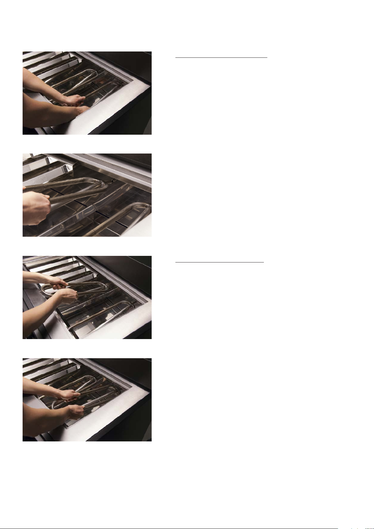
ROCK.AIR.COOK
The tubular burner will come loose from the mixer pipe
at the front, and can now be carefully removed from
above.
Installing the tubular burner:
First, insert the tubular burner at the side furthest from
your body and press it into place.
Insert the tubular burner on the side closest to your
body until it latches into place.
Removing the tubular burner:
Close the gas valve. Ensure that the unit is cooled
down, then:
Grip the tubular burner with both hands and swivel it
away from your body.
This manual suits for next models
9
Table of contents
Popular Cooker manuals by other brands

TECNOEKA
TECNOEKA KCP96 V - KCP96 VS - KCP5 96 V - KCP5 96 VSKC 96... Use and instruction manual

Happiness
Happiness T-6209 Series Operation instructions

CASO DESIGN
CASO DESIGN Comfort C 2000 Original operating manual

Siemens
Siemens Fornuis HX74U538N instruction manual

Baumatic
Baumatic BCE512SS/W user manual

Rayburn
Rayburn OF7 Installation


