Steinsvik Orbit-3100 User manual

Steinsvik AS Rundhaug 25, 5563 Førresfjorden, Norway | +47 52 75 47 00 | post@steinsvik.no | www.steinsvik.no
User manual
Camera System

2
Rev:
Rev. date:
By (initials):
Edits:
A1
10.04.2018
JPH
Created
A2
20.06.2018
IDFR
Added components
A3
04.07.2018
IDFR
Updated
A4
03.09.2018
IDFR
Updated spare parts
A5
23.11.2018
IDFR
Updated with Bracket V-clamp assy chap. 4.6 and 5.2.2
A6
10.12.2018
IDFR
Updated maintenance chapter
A7
21.01.2019
IDFR
Updated information regarding Orbit-310 and maintenance

3
TABLE OF CONTENT
1Introduction.......................................................................................................................................5
1.1 Symbols ....................................................................................................................................6
2Disclaimer.........................................................................................................................................6
3Safety ............................................................................................................................................... 7
3.1 Warranty limitations...................................................................................................................7
3.2 Waste information.....................................................................................................................7
3.3 Assessment of escape risk .......................................................................................................8
4Technical description........................................................................................................................9
4.1 Underwater camera.................................................................................................................10
4.2 Surface camera.......................................................................................................................11
4.3 PSU.........................................................................................................................................12
4.4 Multiwinch ...............................................................................................................................13
4.5 Orbit-bracket for ring...............................................................................................................14
4.6Orbit-bracket for ring with clamp.............................................................................................14
4.7 Antenna and mast...................................................................................................................15
4.8 Strain relief..............................................................................................................................16
4.9 Pulley for camera rope............................................................................................................16
4.10 Pulleyblock 18 mm ..............................................................................................................17
4.11 Camera cable......................................................................................................................17
4.12 Rope Orbit XXXM................................................................................................................17
4.13 Surveillance camera............................................................................................................18
4.14 Fibre receiver cabinet..........................................................................................................20
4.15 Orbit-51X8 for wireless facilities..........................................................................................20
4.16 Protection cabinet for PSU..................................................................................................21
5Preparation and installation............................................................................................................22
5.1 Antenna...................................................................................................................................22
5.2 Orbit Bracket for ring...............................................................................................................22
5.3Mast/Alu pipe ..........................................................................................................................26
5.4 PSU/Protection cabinet...........................................................................................................27
5.5 Winch and winch rope.............................................................................................................28
5.6 Rope and strain relief..............................................................................................................29
5.7Underwater camera.................................................................................................................30
5.8 Surface camera.......................................................................................................................32
5.9 Surveillance camera................................................................................................................32
6Operating instructions ....................................................................................................................33
6.1 Multiwinch/underwater camera ...............................................................................................33
6.2 Surveillance camera................................................................................................................33

4
7Maintenance...................................................................................................................................35
7.1 Routine inspection and periodic maintenance........................................................................35
7.2 Larger reparations and modifications......................................................................................36
7.3 Troubleshooting and correction of errors................................................................................36
7.4 Link to troubleshooting for camera system .............................................................................37
7.5 Storing, preservation and maintenance..................................................................................37
8Spare parts.....................................................................................................................................38
8.1 Underwater camera.................................................................................................................38
8.2 Obrit-200 (411340) and Orbit-210 (430755)...........................................................................38
8.3 Multiwinch (100069)................................................................................................................39
8.4 Orbit-Bracket for ring (405461) ...............................................................................................40
8.5 Orbit-bracket for ring with clamp (V-Clamp) (442778)............................................................41
8.6 Antenna (411859) ...................................................................................................................42
8.7 Strain Relief (420438) .............................................................................................................42
8.8Orbit-310 (410478)..................................................................................................................43
9Orbit-PSU Stainless Steel..............................................................................................................44

5
1 INTRODUCTION
This manual presents the installation, use and maintenance of the complete Steinsvik AS camera
system with associated components.
Consult the NeoVision or Vision user manual for the complete description of navigation and
configurations.

6
1.1 Symbols
The symbols used in this user manual, and their respective meaning, are explained below.
Information
Go to page/chapter or appendices for more information
Show caution –risk of damage to equipment and mild personal injury
Warning –may lead to personal injury
2 DISCLAIMER
Every care has been taken by the staff of Steinsvik AS in compilation of the data contained herein and
in verification of its accuracy when published, however the content of this training manual is subject to
change without notice due to factors outside the control of Steinsvik AS and this manual should therefore
be used as a guide only. For example, the products referred to in this publication are improved
continually through further research and development and this may lead to information contained in this
manual being altered without notice.
This training manual is published and distributed on the basis that the publisher is not responsible for
the results of any actions taken by users of information contained in this training manual based on the
information contained in this manual nor for any error in or omission from this manual. Steinsvik AS
does not accept any responsibility whatsoever for misrepresentation by any person whatsoever of the
information contained in this training manual and expressly disclaims all and any liability and
responsibility to any person, whether a reader of this training manual or not, in respect of claims, losses
or damage or any other matter, either direct or consequential arising out of or in relation to the use and
reliance, whether wholly or partially, upon any information contained or products referred to in this
manual.
7
3 SAFETY
3.1 Warranty limitations
Warranty according to quote.
3.2 Waste information
PSU, winch and camera house are classified as E-waste
Camera house consist mainly of POM, with small amounts of stainless steel.
Orbit-bracket for ring, mast and winch bracket
Bolts, nuts, screws and washers.
The underwater camera with depth sensor contains a small amount of glycol.
When the camera system is in storage and not in use, it will not pose any threat
with regards to pollution. All parts can be recycled.

8
3.3 Assessment of escape risk
A Steinsvik AS camera system will, under normal working conditions, not pose a risk of escape when it
is being used in a cage at a fish farm. The camera system does not consist of any parts that may, under
normal conditions, cause damage to the net, ropes or any other parts of the plastic or steel cage
construction.
Factors
1. The camera’s suspension rope breaks: The camera is designed with no sharp edges, so it poses
no risk for holes or wear on the net/cage, even if it sinks to the bottom of the cage. However, if
the camera is not retrieved after a while, or if it under pressure from the lift-up or other
equipment, this can cause wear and tear on the net.
2. Suspension on the cage edge: The Orbit bracket for ring placed on the cage edge is made out
of strong aluminium and secured with stainless steel bolts and screws. These do not normally
come in contact with the net, but if they are not fastened properly or if they come lose, they may
pose a risk of wear and tear on the net (50-80 cm above water surface)
3. Winch strength: The winch has a built-in load protection and is set to lift 10 kg at sea. Any load
above this will deactivate the engine to avoid the rope/cable/winch controlled by the winch,
getting caught and wear a hole in the net when manoeuvring the winch.

9
Antenna for wireless
connection
4 TECHNICAL DESCRIPTION
Steinsvik AS camera system is an advanced surveillance system to control the feeding of fish in
aquaculture and for general inspection of fish in cages.
The camera system consists of:
- Underwater camera
- Surface camera
- PSU
- Multiwinch
- Bracket for ring
- Antenna
- Aluminium pipe (mast)
- Strain relief (fibre installation only)
- Surveillance camera
- Camera cable
- Pulley for camera rope
- Pulleyblock 18 mm
- Counterweight
- Rope
Camera installation
Surface camera
Protection box PSU
Strain relief (only for
fiber installation)
PSU
Bracket for
ring
Multiwinch
Pulleyblock for camera rope
Rope
Underwater camera
Counterweight
Pulleyblock 18mm
Mast
Camera cable

10
4.1 Underwater camera
Steinsvik AS has five different types of underwater cameras (the Orbit-3000 series) with pan and tilt
function, both with and without active sensors. Figure 1 shows the different models and what sensors
they are equipped with.
The Orbit-3100 is eqipped with both a temperature and depth sensor, however these sensors will only
be available through a software update. This way you do not have to send the camera to service to
receive this update.
Table 1 Specifications Orbit-3000 series
Specifications
Orbit-3100
Orbit-3300
Orbit-3500
Orbit-3400
Orbit-3600
Video signal
PAL
Digital
Resolution
P50, 752x582
HD 1200p
Light sensitivity
0,003 lux
0,0003 lux
Weight
6,5 kg
6,7 kg
IP degree
IP69, down to 100 m
Temperature range
-20°C - +60°C
Effect
24 VDC
Material
POM, stainless steel and PEEK
Optic angle
77° in water
80° in water
Figure 1 Orbit-3000 series
11
4.2 Surface camera
Orbit-200B and Orbit-210 surface camera is mounted on the same aluminium pipe as the PSU on the
cage. The camera is designed as an underwater camera and is therefore waterproof and made from
corrosion resistant material. The camera is intended for permanent installation.
Table 2 Specifications Orbit-200B and Orbit-210
Specifications
Orbit-200
Orbit-210
Video signal
PAL
Digital
Resolution
768x576
1080p (Full HD)
Sensor type
Colour CCD
Colour
Zoom
36 x optic zoom
30 x optic zoom
12 x digital zoom
Lens opening
F 1.4
F1.6
Light sensitivity
0,01 lux –50IRE
0.01 lux (using IR)
Vertical rotation
120°
120°
Horizontal rotation
360°
360°
Weight
2,5 kg
2,5 kg
IP degree
IP68
IP68
Temperature range
-20°C - +60°C
-20°C - +50°C (approved for
Nordic climate only)
Effect
11-13 VDC, 3,9 W
11-13 V (DC), 3.9 W
Material
POM
Aluminium and POM
Picture angle
60,2°
63.7°
Focus
Auto
Auto
Cable length
2 m0F1
2 m
1
Standard length. Can also be delivered with 10 m and 20 m cable
Figure 2 Orbit-200
12
4.3 PSU
The cameras are primarily powered and controlled by the PSU at the cage. In addition, the Orbit-3100,
Orbit-3300 and the Orbit-3500 can be controlled from the control system KB-6000, which is connected
to 230 VAC and conveys low current and control signals to the connected units. The same cameras can
also be connected to the MB-3000 portable control unit which have a built-in screen, joystick and 12 V
power to the camera. See chapter 9 for more specifications.
The PSU
2
also provide power to the Multiwinch.
Table 3 Specifications PSU
Specifications
Material
Stainless/aluminium/fibre glass
Possible camera connections
1, 2 or 4 –depending on which PSU
type
Nominal effect
60 W per camera
300 W when running the winch
Contacts
2 x multi contacts for sensors, surface
camera and antennas
IP degree stainless cabinets
IP67
IP degree fibre glass cabinets
IP66
2
Orbit-510/511, Orbit-515/516, Orbit-518/519, Orbit-578/579 and Orbit-520/521
Figure 3 PSU

13
4.4 Multiwinch
The Multiwinch is mounted on the cage with the Orbit –Bracket for ring and is controlled by the PSU via
a control desk or a computer with the camera software installed. The winch is connected to the PSU
with its own cable.
The winch controls the camera vertically and horizontally in the cage and has a built-in function which
prevents the rope from being driven without stretch.
Table 4 Specifications Multiwinch
Specifications
Material
Stainless steel, POM and
aluminium
Weight
11 kg
Operating voltage
50 VDC nominal
Voltage tolerance
-25% / +50% (37,5 VDC / 75 VDC)
Temperature range
-20°C - +50°C
IP degree
IP67
Fixed cable
5 m
Figure 4 Multiwinch

14
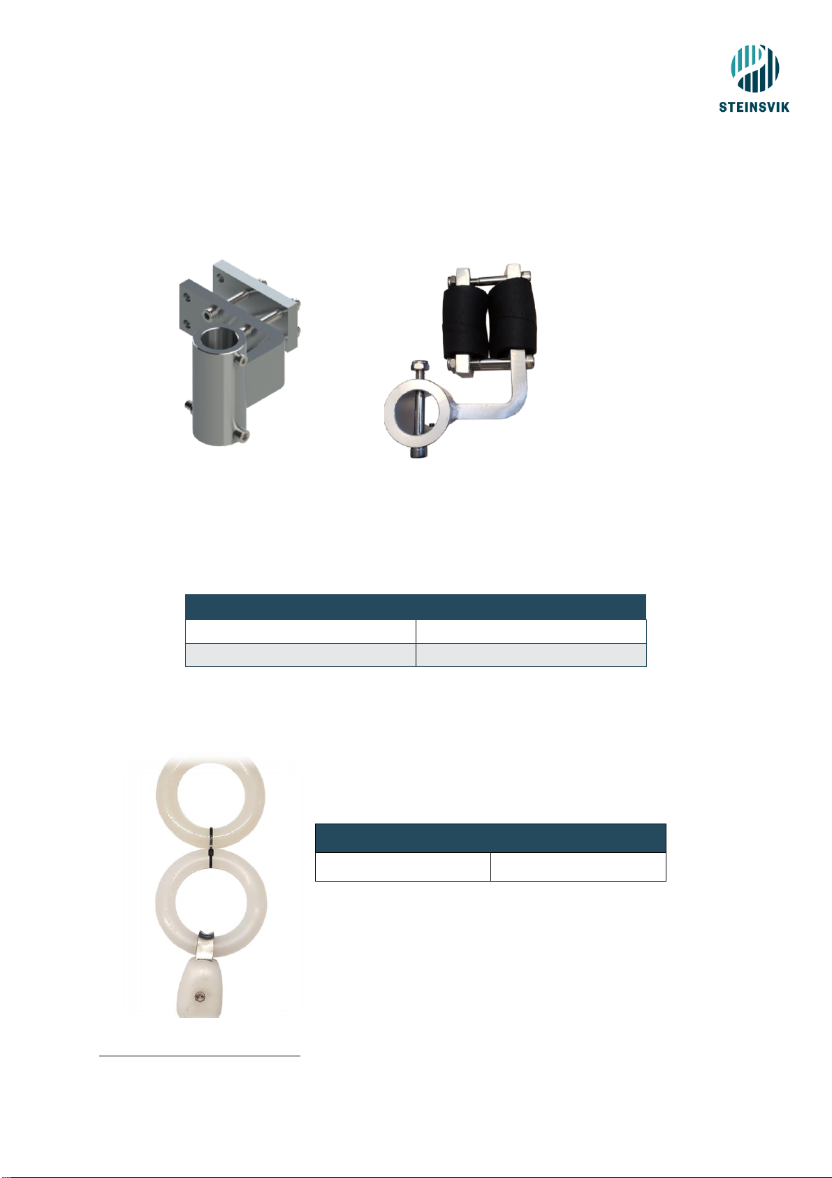
4.5 Orbit-bracket for ring
It is possible to connect the PSU, antenna and Multiwinch to the Orbit-bracket for ring. See chapter 5.2.1
for a description on how to install the bracket for ring.
Orbit-bracket for ring is delivered with a large and a small bottom mounting bracket to accommodate
most of the cages in today’s market.
Figure 5 Bracket with small clamp
Table 5 Specifications Bracket for ring
4.6 Orbit-bracket for ring with clamp
It is possible to connect the PSU, antenna and Multiwinch to the Orbit-bracket
for ring. See chapter 5.2.2 for a description on how to do install the bracket
for ring with clamp.
This version of the Orbit-bracket is delivered with a clamp mounted on the
bottom mounting bracket. This clamp makes it easy to adapt the Orbit-
bracket to all types/sizes of cages available in today’s market.
This bracket can also be delivered with two different sizes of the bottom
mounting bracket. Figure 7 illustrates the Orbit-bracket w/clamp and small
mounting bracket.
Table 6 Bracket for ring with clamp
Specifications
Material
Aluminium and stainless steel
Weight
7,82 kg
Dimensions (WxHxD)
315 x 502 x 553 mm
Specifications
Material
Aluminium and stainless steel
Weight
7,74 kg
Dimensions (WxHxD)
315 x 502 x 553 mm
Attachment
for mast/PSU
Attachment
for Multiwinch
Figure 6 Bracket with large clamp
Figure 7 Bracket with clamp

15
4.7 Antenna and mast
The antenna sends data from the PSU to the barge. The sticker on the antenna must face the receiving
antenna placed on the barge. For more information regarding mounting and installation, see next
chapter.
For wireless facilities, the antenna is attached to the aluminium pipe on arrival. For fibre facilities the
same aluminium pipe is used for mast to attach the fibre equipment.
Table 7 Specifications Antenna and Mast
Specifications
Antenna
Mast
Material
POM-C (white)
Aluminium
Dimensions (WxHxD)
98 x 325 x 98 mm
1500 x 40 mm
Temperature range
-20°C - +70°C
N/A
Power supply
24 V, 0,5 A (12 W),
max 5,5 W
N/A
Humidity during
operation
5-95%
condensation
N/A
Maximum power
consumption
5 W
N/A
Weight (kg)
1,63
Figure 8 Antenna and mast
16
4.8 Strain relief
The strain relief is delivered with all PSU’s and is used with the fibre cables. It is normally padded before
use.
Table 8 Specifications strain relief
Specifications
Material
Aluminium and stainless steel
Weight
1,5 kg
4.9 Pulley for camera rope
3
Table 9 Specifications –Pulley for camera rope
Specifications
Material
Nylon and stainless steel
3
Strips are only for easier transportation –not used in the cage.
Figure 9 Strain relief
Figure 10 Padded strain relief
Figure 11 Pulley for camera rope
17
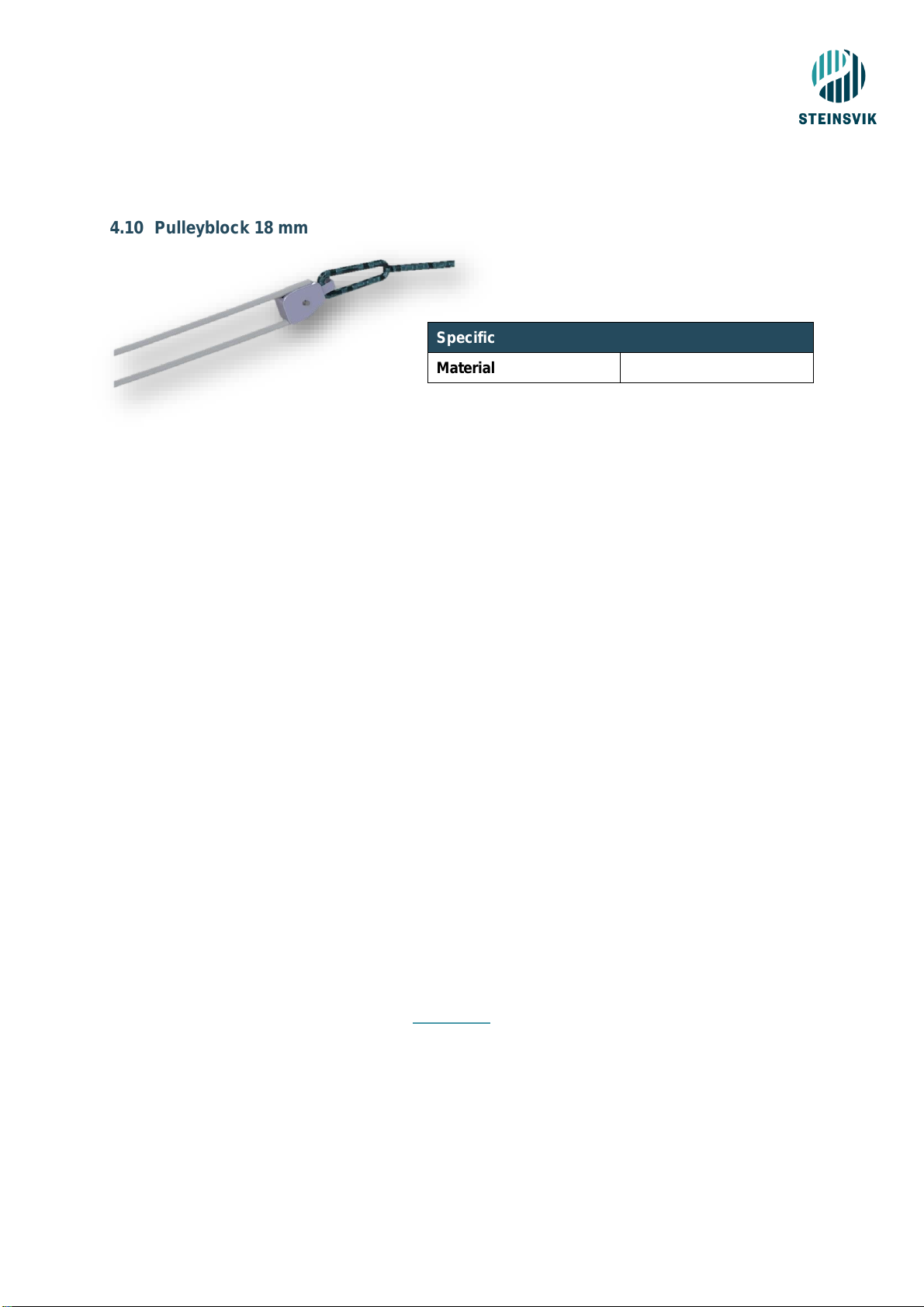
4.10 Pulleyblock 18 mm
Table 10 Specifications - Pulleyblock
4.11 Camera cable
Steinsvik’s camera cable transfer all signals from the PSU to the camera. The cable can be delivered in
many different lengths, depending on what is required at the locations. It is delivered either as a blue
cable or a black cable where the black cable is enhanced with Kevlar on the outside, while the blue is
not enclosed in Kevlar.
To ensure the best possible utilisation of the system, the recommended length of the cable is diagonally
from the winch to the bottom of the cage on the opposite side.
4.12 Rope Orbit XXXM
Rope Orbit-XXXM can be delivered in many different lengths, all adjusted to the cage in which it is to be
used at. The rope is held tight by the counterweight located outside of the cage, on the oposite end of
where the winch is placed. The counterweight adjust the winchrope according to the movement of the
cage.
Standard lengths for cages are:
- 120M cage: 80M
- 160M cage: 100M
- 200M cage: 120M
When using steel cages, the standard delivery is the size of the cage x2 (ie. 24; cage = 50M rope).
The importance of correct installation is due to the winch experience. The user will have a very slow
experience trying to control the winch if the rope have not been installed correctly. The rope is to be
winded out so that all white and blue lines of the rope are parralell. This might take some time to do
properly, but it is worth spending some time on it in order to save much time at a later stage.
More details about mounting is explained in chapter 5.6.
Specifications
Material
Nylon and stainless steel
Figure 12 Pulleyblock
18
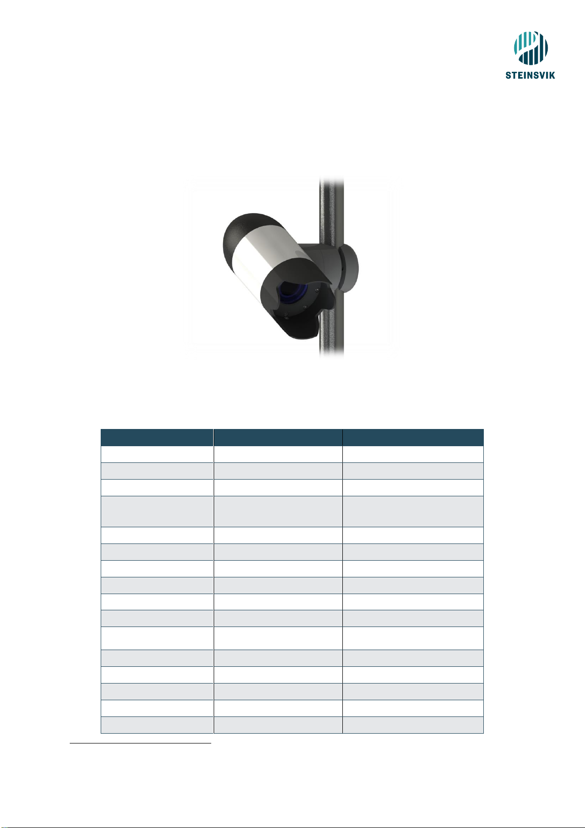
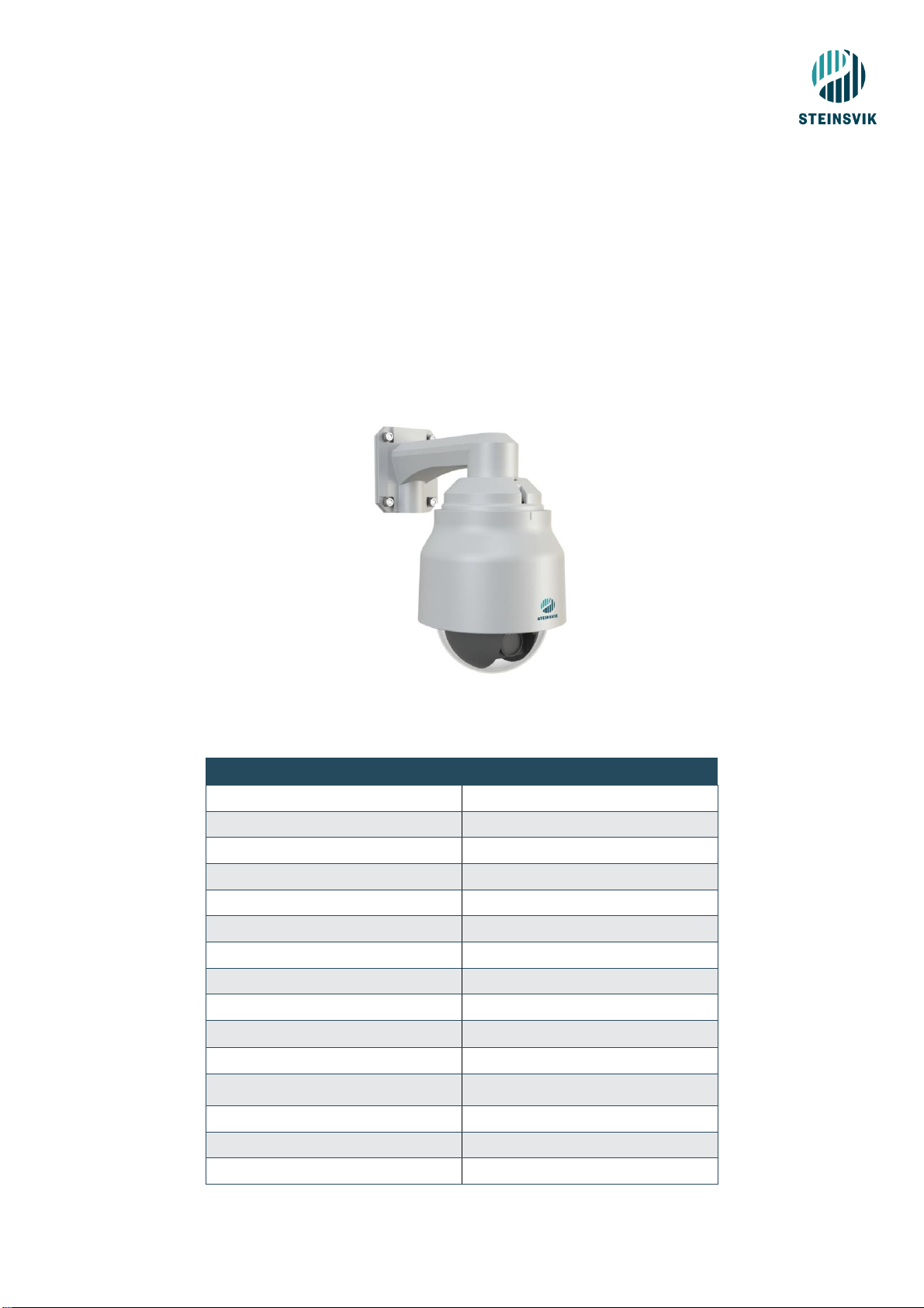
4.13 Surveillance camera
Steinsvik also supplies several surveillance cameras meant for surveillance at the barge. The Orbit-351
and the Orbit-310 are reliable cameras that provides good visibility on the facility and specific parts of
the facility.
4.13.1 Orbit-310
With careful installation of the Orbit-310, you will gain maximum advantage of the camera. The camera
can easily be controlled with a gamepad and has an excellent zoom. In addition to manual control, the
camera can be pre-set to fixed positions via the software. The software allows for control of the camera
with only a keystroke where you can position the camera from the spreader in the outer most edge of
the cage, to the distribution valve at the barge. The Orbit-310 must only be installed at the barge –for
cage installation use Orbit-200/210.
Table 11 Specifications Orbit-310
Specifications
Video signal
Video over IP
Resolution
Full HD 1080p
Sensor type
Colour BSI CMOS
Zoom
30 x optic, 12 x digital
Lens opening
F 1.6
Light sensitivity
0,0015 lux –50 IRE
Weight
10,5 kg (incl. cable)
IP degree
IP67
Temperature range
-10°C - +50°C
Effect
11-13 VDC, 24 VAC or PoE +30W
Material
Aluminium, PC and POM
Range of motion
360° (horizontal), 90° (vertical)
Focus
Auto
Cable length
30 M
Pan/tilt
Manual and Auto
Figure 13 Orbit-310

19
4.13.2 Orbit-351
The Orbit-351 Stationary Camera is a great tool to help maintain the safety of the crew in areas with
less activity, while at the same time having full monitoring of the spaces on the barge you may want.
This camera can also be used for monitoring the amount of feed in the silo. It is easy to install and
integrate in the software.
Table 12 Specifications - Orbit-351
Specifications
Video signal
Video over IP
Resolution
Full HD 1080p
Sensor type
Colour CMOS
Zoom
3x manual optic
Lens opening
F 1.4
Light sensitivity
0,03 lux –50IRE
Weight
2 kg
IP degree
IP68
Temperature range
-20°C - +50°C
Effect
12VDC, PoE
Material
Aluminium, PC and POM
Picture angle
113° (horizontal)
Focus
Manual
Pan/tilt
Manual
Figure 14 Orbit-351

20
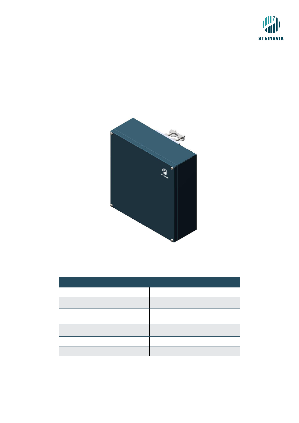
4.14 Fibre receiver cabinet
The Orbit-502 IP Receiver cabinet is the receiving cabinet for fibre installations on the barge. The cabinet
receive and transmit the signals given from the gamepad to the camera. It can be connected to dome
cameras and has the possibility of connecting to sensors. The sensors are not included in the standard
delivery and must be ordered separately.
Table 13 Specifications Fibre receiver cabinet
Specifications
Material
Aluminium and stainless
steel
Weight
10,10 kg
Dimensions (WxHxD)
500 x 550 x 221 mm
Connections
1 x 230 V power inn
3 x multi connector
1 x 100 Mbit/s Ethernet
2 x 100 Mbit/s Ethernet
2 x Hybrid fibre contact
4.15 Orbit-51X8 for wireless facilities
The Orbit-51X8 is the heart of wireless facilities. It receives and transmit all signals in a digital wireless
facility. The Orbit-51X8 has the possibility of connecting to dome cameras and it is possible to upgrade
the cabinet to accommodate sensor connections as well.
Table 14 Specifications Orbit-51X8
Specifications
Material
Aluminium and stainless steel
Weight
10,90 kg
Dimensions
(WxHxD)
555 x 351,3 x 408 mm
Connections
1 x 230 V power inn
2 x multi connector
7 x PoE 100 Mbit/s Ethernet
7 x 100 Mbit/s Ethernet
Figure 15 Fibre Receiver Cabinet
Figure 16 Orbit-51X8
This manual suits for next models
6
Table of contents
Other Steinsvik Digital Camera manuals

 Basic instruction manual")


