INTRODUCTION TO THE MODEL C MUSIC SYSTEM
Safety Warnings
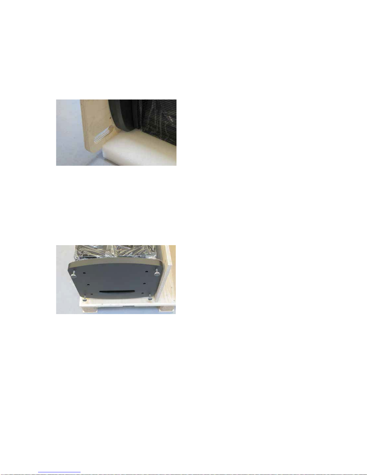
Physical Handling
The Model C components – especially the loudspeaker systems – are very heavy and large. They can
be difficult to handle. Follow all instructions for unpacking and installation. Use ergonomically correct
body positions. Be careful not to unbalance the large speaker systems during handling. Steinway
Lyngdorf cannot be held responsible for any physical damage which occurs during the installation
process.
Electrical Safety
The Model C system must be connected to the mains power system using the supplied power cables
only. The mains voltage has been factory set according to your territory (115 or 230 V). The voltage
setting can only be changed by an authorized technician. Use only mains power cables and power
plugs approved by Steinway Lyngdorf. Otherwise you may cause damage to the electronics and
infringe the warranty. Use only link cables – CAT-5E – approved by Steinway Lyngdorf. Using non-
approved cables, for instance with improper shielding, represents a major risk of violating EMC and
FCC rules for harmful noise radiation.
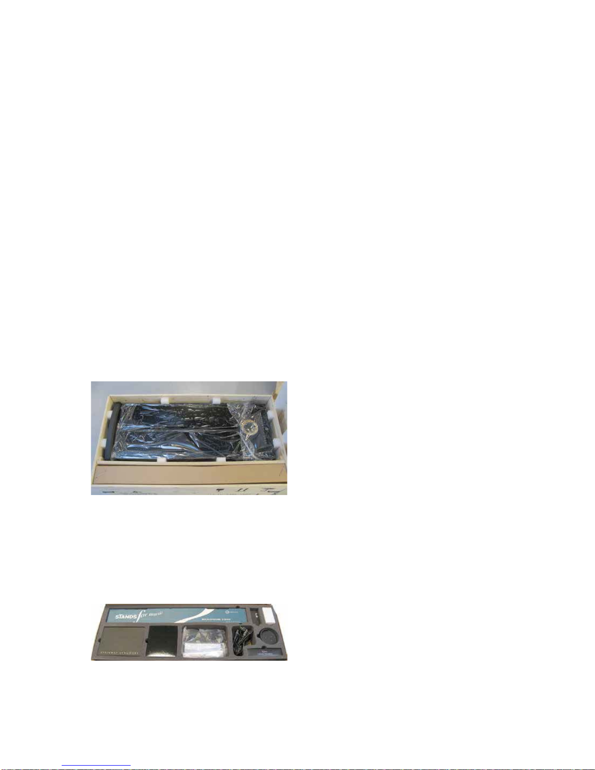
Accessories Included
In the system accessories box, located in the head unit crate, you will find a complete set of link
cables for use between head unit, speakers, and boundary woofers, a measurement microphone, a
microphone stand, and cable for calibration of the RoomPerfect™ system. For handling during
installation, several pairs of white gloves have been included in the accessory pack.
Preparing for Cabling
Steinway Lyngdorf Model C Music System has two pieces of 10 meters (33 feet) of CAT-5E link cable
and four pieces of 1.8 meter (6 feet) power cable included in the accessory pack.
Home Automation System Integration
Model C is compatible with home automation systems. The system accessory pack includes a remote
interface box for wireless transmission of the control signals. The remote interface box contains a RS-
232 interface with 9 pin Sub-D connector. Information about protocol etc. can be obtained from
Steinway Lyngdorf.
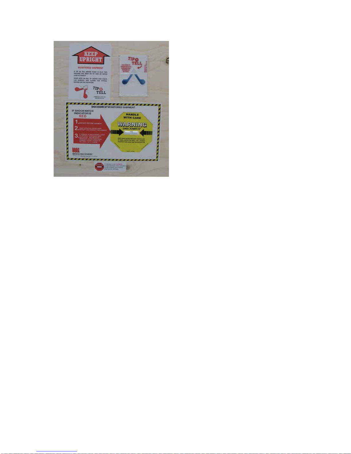
Checking Shipping Monitors on Arrival
To ensure proper transportation, all crates have Shockwatch and Tip’N’Tell monitors that will detect
any improper handling. On arrival, check these monitors. If indicators have been activated, always
accept shipment, note activation on bill of lading, and inspect the crates for potential damage inside.
4