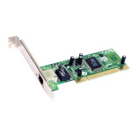
Step Technica HLSB-36PCI2 User manual

HLS(MKY36)PCI Board
HLSB-36PCI2
User's Manual
STD_HLSB36PCI2_V1.0E

1. The information in this document is subject to change without prior notice.
Before using this product, please conrm that this is the latest version of document.
2. Technical information in this document, such as explanations and circuit examples, are just for
references to use this product in a proper way.
When actually using this product, always fully evaluate the entire system according to the design
purpose based on considerations of peripheral circuits and environment.
We assume no responsibility for any incompatibility between this product and your system.
3. We assume no responsibility whatsoever for any losses or damages arising from the use of the
information, products, and circuits in this document, or for infringement of patents and any other
rights of a third party.
4. When using this product and the information and circuits in this document, we do not guarantee
the right to use any property rights, intellectual property rights, and any other rights of a third
party.
5. This product is not designed for use in critical applications, such as life support systems.
Contact us when considering such applications.
6. No part of this document may be copied or reproduced in any form or by any means without
prior written permission from StepTechnica Co., Ltd.
Notes

HLSB-36PCI2 User's Manual
Revision history
Date Version Content Note
AUG 2018 1.0E Issued the rst edition

HLSB-36PCI2 User's Manual
Preface
This manual describes HLSB-36PCI2, PCI board with MKY36 which is a kind of HLS family IC.
Be sure to read "HLS Introduction Guide" in advance to use HLSB-36PCI2 and understand this manual.
● Target readers
・Those who rst build an HLS
・Those who rst use StepTechnica's HLSB-36PCI2 to build an HLS
● Prerequisites
This manual assumes that you are familiar with :
・Network technology
・Semiconductor products (especially microcontrollers and memory)
● Related manuals
・HLS Introduction Guide
・HLS Technical Guide
・MKY36 User's Manual
【Note】
Some terms in this manual are dierent from those that used in our website or product brochures. The brochure uses
ordinary terms to help many people in various industries understand our products.
Expertise in HLS family, please understand technical information based on technical documents (manuals).

Table of Contents
HLSB-36PCI2 User's Manual
Chapter 1 Hardware
Chapter 2 Software
1.1 Features ............................................................................................................................................................................................................. 1-1
1.2 Specications .................................................................................................................................................................................................. 1-1
1.3 Connector specications ............................................................................................................................................................................ 1-2
1.4 DIP switches .................................................................................................................................................................................................... 1-3
1.5 Memory map ................................................................................................................................................................................................... 1-4
1.5.1 MKY36 ..................................................................................................................................................................................................... 1-4
1.5.2 Unique register of HLSB-36PCI2 ................................................................................................................................................... 1-5
1.6 The access without driver software ....................................................................................................................................................... 1-6
2.1 Outline ............................................................................................................................................................................................................... 2-1
2.2 Copyright and disclaimer ........................................................................................................................................................................... 2-1
2.3 File structure .................................................................................................................................................................................................... 2-2
2.4 Restrictions ....................................................................................................................................................................................................... 2-2
2.4.1 Multi-thread .......................................................................................................................................................................................... 2-2
2.4.2 Interrupt handling .............................................................................................................................................................................. 2-3
2.5 API functions ................................................................................................................................................................................................... 2-4
2.5.1 HlsbGetVersion .................................................................................................................................................................................... 2-5
2.5.2 HlsbGetLastError ................................................................................................................................................................................. 2-6
2.5.3 HlsbSearchBoard ................................................................................................................................................................................. 2-7
2.5.4 HlsbOpenHandle ................................................................................................................................................................................. 2-8
2.5.5 HlsbCloseHandle ................................................................................................................................................................................. 2-9
2.5.6 HlsbReadWord ...................................................................................................................................................................................2-10
2.5.7 HlsbWriteWord ..................................................................................................................................................................................2-11
2.5.8 HlsbReadData .....................................................................................................................................................................................2-12
2.5.9 HlsbWriteData ....................................................................................................................................................................................2-13
2.5.10 HlsbResetBoard ...............................................................................................................................................................................2-14
2.5.11 HlsbGetInt0Counter, HlsbGetInt1Counter ...........................................................................................................................2-15
2.5.12 HlsbClearInt0Counter, HlsbClearInt1Counter .....................................................................................................................2-16
2.5.13 HlsbGetInt0StatusInfo, HlsbGetInt1StatusInfo ...................................................................................................................2-17
2.5.14 HlsbClearInt0StatusInfo, HlsbClearInt1StatusInfo .............................................................................................................2-18
2.6 Sample program ..........................................................................................................................................................................................2-19
2.6.1 Sample of access to MKY36#1 .....................................................................................................................................................2-19
2.6.2 Sample of access to MKY36#2......................................................................................................................................................2-20
2.6.3 Sample of interrupt handling ......................................................................................................................................................2-21

HLSB-36PCI2 User's Manual
Figures
Tables
Table 1-1 Board specications ...................................................................................................................................................................... 1-1
Table 1-2 Memory map .................................................................................................................................................................................... 1-4
Table 2-1 API functions .................................................................................................................................................................................... 2-4
Table 2-2 Version numbering ........................................................................................................................................................................ 2-5
Table 2-3 Error code list ................................................................................................................................................................................... 2-6
Table 2-4 Internal structure of Int0Info, Int1info .................................................................................................................................2-17
Fig.1-1 Panel view .............................................................................................................................................................................................. 1-2
Fig.1-2 Connector peripheral circuits ......................................................................................................................................................... 1-2
Fig.1-3 Settings of HLSB-36PCI2 board ..................................................................................................................................................... 1-3

Chapter 1 Hardware
1-1
1.1 Features
HLSB-36PCI2 is a PCI expansion bus supported HLS communication board with MKY36 chip. This product is
designed to help easy operation of MKY36 functions with StepTechnica's Library for Windows.
HLSB-36PCI2 is for evaluating and learning MKY36.
1.2 Specications
Table 1-1 Board specications
Chapter 1 Hardware
This chapter describes hardware of HLSB-36PCI2.
HLSB-36PCI2 is adopting 8-pin modular connector to evaluate operation with commercial CAT-5 or more greater
straight-through cable for 100BASE-TX.
Experience of using HLSB-36PCI2 will be a clue for microcontroller embedded system with MKY36.
The specications of HLSB-36PCI2 are shown in Table 1-1.
Type HLSB-36PCI2
Type of IC MKY36 × 2pcs
Communication method HLS communication method (full-duplex, half-duplex)
Baud rate 3Mbps/6Mbps/12Mbps
Supported bus PCI Ver2.2 supported, 32bit / 33MHz expansion bus 5V / 3.3V
supported (Low prole supported)
Owned resource 16KB serial memory area (Automatically allocated by PnP)
Interrupt 1 line used (Automatically allocated by PnP)
Connector RJ-45 modular connector:TM11R-5M2-88-LP
Power supply DC +5V
Consumption current 500mA or less
Atmospheric conditions Temperature 0 to 50 ℃ Humidity 20 to 90%(With no condensation)
Size 119.9mm(W) × 64.4mm(D) ※ Not including panel
Two MKY36 ICs are mounted on HLSB-36PCI2 board.
Hereinafter, MKY36 (IC7) is reered to MKY36#1 and MKY36(IC8) is reered to MKY36#2.

HLSB-36PCI2 User's Manual
1-2
1.3 Connector specications
Fig.1-2 Connector peripheral circuit
The panel view of HLSB-36PCI2 and its details are shown in Fig.1-1.
CHK1,2(Yellow+Red)
SCAN(Green)
SCAN(Green)
CHK1,2(Yellow+Red)
Panel
Fig.1-1 Panel view
CN2 / CN3 connector peripheral circuit is shown in Fig.1-2.
Panel(F.G.)
Panel(F.G.)
Connectiondiagramoffull-duplexmode
Pin# Function
Full-duplex Half-duplex
3RX+ --
4 TX- TRX-
5 TX+ TRX+
6 RX- --
8 Shield Shield
1,2,7 Unused Unused
SCAN LED is connected to #SCANL pin of MKY36, lit green when MKY36 is scanning.
CHK1, 2
LED is connected to #CHK1L and #CHK2L pin of MKY36. Lit yellow when CHECK-1 is
occurring, lit red when CHECK-2 is occurring.
LED lit red if CHECK-1 and CHECK-2 are occurring at the same time.
CN2, CN3
HLS communication line
Commercial CAT-5 or more greater straight-through cable for 100BASE-TX can be used.
Be sure that this is not for an Ethernet board.
Panel
Panel is connected to a PC case front panel. Connect a PC case to F.G. in accordance with the PC
manual. Metal shell of CN2 / CN3, and No.8 pin can be connected to the panel by making R33
PAD and R43 PAD on the board shorted. (Refer to Fig.1-2, Fig.1-3.)

Chapter 1 Hardware
1-3
1.4 DIP switches
Fig.1-3 Settings of HLSB-36PCI2 board
The settings of DIP switches of HLSB-36PCI2 are shown in Fig.1-3.
If two or more HLSB-36PCI2 devices are connected to one PC, set SW9 board IDs to individual number of each
boards so that you can distinguish the boards using software. (Factory setting board ID : 0)
HLSB-36PCI2 supports both of full-duplex and half-duplex mode.
Note that the setting method of SW is dierent between MKY36#1 and MKY36#2.
Full/Halfsetting
BoardIDsetting
Full/Halfsetting
Notch1-2(left) Notch2-3(right)
Notch1-2(left) Notch2-3(right)
Panel(F.G.)connectingpad
(*) MKY36#1
・Full-duplex :Set SW1 and SW2 to 2-3. (Factory setting)
・Half-duplex :Set SW1 and SW2 to 1-2.
(*) MKY36#2
・Full-duplex :Set SW5 and SW6 to 1-2. (Factory setting)
・Half-duplex :Set SW5 and SW6 to 2-3.
HLSB-36PCI2 is always at a termination of multi-drop connection (an end of network cable).
For this reason, termination is always being enabled.

HLSB-36PCI2 User's Manual
1-4
1.5 Memory map
Table 1-2 describes memory map of HLSB-36PCI2. Two MKY36 ICs are mounted on this product.
An address in memory map is a relative value from starting address of HLSB-36PCI2, and actual address is the value
which is added the starting address of the board.
Table 1-2 Memory map
Address Content
000H - 595H MKY36#1
596H - 7FFH Unused
800H - D95H MKY36#2
D96H - EFFH Unused
F00H Chip Reset Register
F02H Board ID Register
F04H - FFFH Unused
Two MKY36 ICs are mounted on HLSB-36PCI2.
MKY36#1 on the board is mapped to 000H to 595H.
MKY36#2 on the board is mapped to 800H to D95H.
For the details of memory map of MKY36, refer to "2.1 Memory map" in MKY36 User's Manual.
1.5.1 MKY36

Chapter 1 Hardware
1-5
1.5.2 Unique register of HLSB-36PCI2
F00H and F02H registers shown in Table 1-2 Memory map are unique registers of HLSB-36PCI2.
The details of these registers are described in the following.
Chip Reset Register Address:F00H
bit 15 14 13 12 11 10 9 8 7 6 5 4 3 2 1 0
R/W R R R R R R R R R R R R R R W W
Function -- -- -- -- -- -- -- -- -- -- -- -- -- -- CRST1 CRST0
[Function] By writing "1" to CRST0 (Chip ReSet 0), reset signal can be applied to RST pin of MKY36#1.
A reset term to RST pin is 100ms.
This register is write-only, so data will be undened when reading the register.
Board ID Register Address:F02H
bit 15 14 13 12 11 10 9 8 7 6 5 4 3 2 1 0
R/W R R R R R R R R R R R R R R R R
Function -- -- -- -- -- -- -- -- -- -- -- -- -- -- BID1 BID0
[Function] The value of board ID set in SW9 can be obtained by reading BID0, 1 (Board ID).
For the details, refer to "1.4 DIP switches".
Do not access to unused area ("596H to 7FFH", "D96H to EFFH", and "F04H to FFFH") shown in
Table 1-2 Memory map.
It can make a whole system unstable.
By writing "1" to CRST1 (Chip ReSet 1), reset signal can be applied to RST pin of MKY36#2.
A reset term to RST pin is 100ms.
This register is write-only, so data will be undened when reading the register.

HLSB-36PCI2 User's Manual
1-6
1.6 The access without driver software
When you directly access to HLSB-36PCI2 without StepTechnica's driver software, note the following point.
Always use 32bit access to access to HLSB-36PCI2. At that time, lower 16 bit data will be used and upper 16 bit
will be unused.
For this reason, address to access needs to be specied 2 times longer than memory map mentioned above.
For example, in order to read 200H address of MKY36#1, make the lower 16bit in 400H of HLSB-36PCI2 obtain 2
bytes data in 200H of MKY36#1 by executing 32bit Read.
In addition, in order to write to 180H address of MKY36#2, the lower 16bit out of written 32bit data is written to
180H of MKY36#2 by 32bit Write to 1300H of HLSB-36PCI2.
This access method applies to HLSB-36PCI2 unique register.

Chapter 2 Software
2-1
2.1 Outline
2.2 Copyright and disclaimer
Chapter 2 Software
This chapter describes API provided by StepTechnica.
The driver software and DLL are recorded in HLSB-36PCI2 attached disk.
For rst powering up a PC with HLSB-36PCI2 connected, install the driver from the attached disk in accordance with
"Add Hardware Wizard" on Windows.
At log in, note this procedure needs the Administrator account to install the device driver.
Due to the specications of Windows, any accesses to HLSB-36PCI2 from user application are executed via API in
the attached HLSB36PCI2.DLL.
When using Microsoft Windows 7 / 8 as a host OS, these attached software optimizes the control to HLSB-36PCI2 by
utilizing many programing tools such as Microsoft Visual Studio.
For the details of supported OS and the latest software information, refer to our website.
(http://www.steptechnica.com/en/index.html)
All documents, programs and program sources are belong to StepTechnica Co., Ltd.
The individuals, companies or other parties only who accept the cautions written below and use our HLSB-36PCI2
are licenced to copy or use of these works of StepTechnica Co., Ltd.
You can not be revised and re-distribution or duplication and use some or all of the work other than this product
without prior notice.
① StepTechnica Co., Ltd. assume no responsibility for any results caused by using the attached
driver disk or all software downloaded from our website.
② Use API in proper ways with its instructions.
③ All specications and contents are subject to change without prior notice.
We do not guarantee for forward compatibility.
④ We can not support for an inquiry regarding operating systems and development
environment.
⑤ If you have found any errors and failures, contact our R&D department.

HLSB-36PCI2 User's Manual
2-2
2.3 File structure
Files stored in "DLL" folder in the attached disk are the following.
【hlsb36pci2.dll】
DLL body :
Use this within Windows system folder or user program directory using this DLL.
【hlsb36pci2.lib】
Import library for Microsoft Visual C/C++, which is created using VisualStudio2013
【hlsb36pci2.h】
Header le for HLSB-36PCI2.
Include this after than Windows.h when using.
2.4 Restrictions
This chapter describes the restrictions at building an application using this API.
API in DLL can not be used from other threads at the same time.
In the case that an application has multithreading structure, be sure not to be called from other thread at the same
time.
2.4.1 Multi-thread

Chapter 2 Software
2-3
INT0R and INT1R registers enable MKY36 to set enable/disable of interrupt and to check the status of interrupt
occurrence.
The internal driver has registers called interrupt factor register which retains the information in lower 8 bit of INT0R
and INT1R at interrupt occurrence and interrupt count register which retains the interrupt occurrence count of each
INT0R and INT1R. The internal driver process the following procedure using these registers at interrupt occurrence.
(For instance, below describes when interrupt occurred at INT0.)
2.4.2 Interrupt handling
An API function is provided to obtain and clear the information from interrupt factor register and interrupt count
register.
① Set the interrupt factor information in interrupt factor register.
(Previous interrupt factor remains until be cleared by interrupt factor register from user application.)
② Increment the value of interrupt count register.
③ Clear interrupt factor by writing "1" to the bit which is set "1" in 0-7 bit of INT0R.
(1) A function which returns the value of interrupt count register (HlsbGetInt0Counter, HlsbGetInt1Counter)
The internal driver retains interrupt count of each INT0, INT1 registers from MKY36#1/#2. This function
returns the count value.
(2) Clear function of interrupt count register (HlsClearInt0Counter, HlsbClearInt1Counter)
Clears interrupt count register
(3) A function which returns the value of interrupt factor register (HlsbGetInt0StatusInfo, lsbGetInt1StatusInfo)
The internal driver retains interrupt factor of each INT0, INT1 registers from MKY36#1/#2.
This function returns the information from interrupt factor register.
(4) Clear function of interrupt factor register (HlsbClearInt0StatusInfo, HlsbClearInt1StatusInfo)
Clears the interrupt factor register
On user application, check the interrupt count from MKY36#1/#2 and interrupt factor using these
functions.

HLSB-36PCI2 User's Manual
2-4
2.5 API functions
The supported API functions are listed in Table 2-1.
Each of API descriptions are shown below.
Function Description
HlsbGetVersion Obtains liblary version number
HlsbGetLastError Obtains the termination status of API functions
HlsbSearchBoard Obtains the number of HLSB-36PCI2 board connected to PC and
its board ID
HlsbOpenHandle Opens the handle of HLSB-36PCI2
HlsbCloseHandle Closes the handle of HLSB-36PCI2
HlsbReadWord Read access to HLSB-36PCI2
HlsbWriteWord Write access to HLSB-36PCI2
HlsbReadData Specied word length read access to HLSB-36PCI2
HlsbWriteData Specied word length write access to HLSB-36PCI2
HlsbResetBoard Resets MKY36
HlsbGetInt0Counter
HlsbGetInt1Counter Obtains INT0, INT1 interrupt count retained in the internal driver
HlsbClearInt0Counter
HlsbClearInt1Counter Clears INT0, INT1 interrupt count retained in the internal driver
HlsbGetInt0StatusInfo
HlsbGetInt1StatusInfo Obtains INT0, INT1 interrupt factor retained in the internal driver
HlsbClearInt0StatusInfo
HlsbClearInt1StatusInfo
Clears specied INT0, INT1 interrupt factor retained in the internal
driver
Table 2-1 API functions

Chapter 2 Software
2-5
2.5.1 HlsbGetVersion
UINT HlsbGetVersion(void);
Format
Returns API version number
Function
None
Parameter
Unsigned integer value which describes the version number of API
Return value
The error code and error factor returned by HlsbGetLastError after executing this function is as follows.
Error code
[Note]
You can ensure the security by checking compatibility between DLL with user application with hlsb36pci2.dll
(not necessarily).
In this article, the word 'security' means to avoid an unexpected shutdown by eliminating incompatible function
call in advance.
The version number returned by this API is shown in Table 2-2.
The reasons for updating the version number are as follows.
Major Number : The revision with no backward compatibility such as API specication change.
Minor Number : The revision with backward compatibility such as an addition of API function.
Update Number : The revision with no specication change such as bug xes.
The updates of Minor or Update Number do not inuence on compatibility. When the value of Major Number
has been changed, it is better not to call API.
This compatibility check needs to be done before initializing.
Table 2-2 Version numbering
Return value
(Example)
Major Number
(Bit 15 - 8)
Minor Number
(Bit 7 - 4)
Update Number
(Bit 3 - 0)
0x0102 1 0 2
0x1398 13 9 8
HLSB_SUCCESS Terminated normally

HLSB-36PCI2 User's Manual
2-6
2.5.2 HlsbGetLastError
UINT HlsbGetLastError(void);
Format
Obtains the termination state of the API called last time
Function
None
Parameter
The error codes supported by this API is shown in Table 2-3, which are dened in hlsb36pci2.h.
Return value
Table 2-3 Error code list
Character constant Value Description
HLSB_SUCCESS 0 Terminated normally
HLSB_ERR_DEVICE_NOT_EXIST 1 Device does not exist.
HLSB_ERR_ALREADY_OPENED 2 Handle has already opened.
HLSB_ERR_CLOSED 3 HlsbOpenHandle() has never been called.
HLSB_ERR_INVALID_HANDLE 4 Invalid handle value
HLSB_ERR_INVALID_PARAM 5 Called with invalid parameter
HLSB_ERR_NO_RESOUCE 6 No resource to execute the process
HLSB_ERR_FAILED 7 The process failed due to unknown reason.
HLSB_NOT_CALLYET 99 API function has never been called.

Chapter 2 Software
2-7
2.5.3 HlsbSearchBoard
BOOL HlsbSearchBoard(BYTE *board_num , BYTE *board_id_list);
Format
Returns the number of HLSB-36PCI2 board connected to PC and its board ID list.
No more than ve units can be identied in one PC.
Function
Parameter
Succeeded : TRUE is returned. Failed : FALSE is returned.
You can check the details of error factor by executing HlsbGetLastError.
Return value
Error code
[Note]
The board ID can be set using SW9 on HLSB-36PCI2.
If two or more HLSB-36PCI2 are connected to a PC, each unit can be distinguished by board IDs.
This API can distinguish up to four HLSB-36PCI2 boards.
When using API, specify the byte type array as a parameter as shown below.
BYTE board_num;
BYTE board_id_list[4];
HlsbSearchBoard(&board_num, &board_id_list[0]);
As an example, three HLSB-36PCI2 units are connected to a PC, and each board IDs are set in sequence ;
1st board ID = 0, 2nd board ID = 1, 3rd board ID = 2.
If the units have been identied by the PC in sequence with rst, third, and second, and run HlsbSearchBoard,
board number and its IDs are returned as follows.
board_num = 3;
board_id_list [0] = 0、board_id_list [1] = 2、board_id_list [2] = 1、board_id_list [3] = 0xFF
HLSB_SUCCESS Terminated normally
HLSB_ERR_INVALID_PARAM NULL has been specied to *board_num.
HLSB_ERR_FAILED The process failed due to unknown reason.
*board_num A pointer to the variable in which to set the number of boards
The meanings of set values are as follows.
・0 : Not connected
・1 to 4 : Number of boards identied
・-1 : Five or more
*board_id_list To receive the board ID, specify a address which has an unsigned char array of four
elements (bytes). It is also possible to specify NULL.
If NULL has been specied, only the number of boards are counted.
The meanings of set values are as follows.
・0 to 3 : Board ID information
・0xFF : Not identied

HLSB-36PCI2 User's Manual
2-8
HANDLE HlsbOpenHandle(int index_no)
Format
Obtains the handle value of HLSB-36PCI2
Function
Parameter
Succeeded : 1 or greater value is returned to the specied index number.
Failed : -1 is returned.
You can check the details of error factor by executing HlsbGetLastError.
Return value
2.5.4 HlsbOpenHandle
Error code
[Note]
If only one HLSB-36PCI2 board is connected to a PC, you can simply execute HlsbOpenHandle (0); not
HlsbSearchBoard.
When two or more HLSB-36PCI2 are connected to a PC, execute "HlsbSearchBoard" in advance to check which
HLSB-36PCI2 to manipuate.
As an example, three HLSB-36PCI2 units are connected to a PC, and each board IDs are set in sequence ;
1st board ID = 0, 2nd board ID = 1, 3rd board ID = 2.
To obtain the handle value of Board ID = 2 via user application, operate as follows.
BYTE board_num;
BYTE board_id_list[4];
HlsbSearchBoard(&board_num, &board_id_list[0]);
Check if the Board ID=2 (the board to manipulate) is set in board_id_list[4].
board_id_list[0] = 0, board_id_list[1] = 2, board_id_list[2] =1, board_id_list[3] = 0xFF
In this case, you see that the board ID to manipulate is set in “board_id_list[1]”.
That means 1 is the index number to set as a parameter of HlsbOpenHandle.
HlsbOpenHandle(1);
Close the handle by HlsbCloseHandle at nishing a program.
HLSB_SUCCESS Terminated normally
HLSB_ERR_DEVICE_NOT_EXIST Device does not exist.
HLSB_ERR_FAILED The process failed due to unknown reason.
index_no Index number
You can select the second or later if two or more HLSB-36PCI2 are connected to a PC.
If just one HLSB-36PCI2 is connected to PC, set 0.
For more information, see "Note".
Table of contents
Other Step Technica PCI Card manuals
