STEP ME800 Series User manual

ME800 High-voltage Inverter Operation Instruction
I
Shanghai Sigriner STEP Motor Co., Ltd
ME800 Series High Voltage Inverter
User Manual
Shanghai Sigriner STEP Electric Co.,Ltd
Shanghai, China
1560# Siyi Road, Jiading district, Shanghai
Postcode:201801
Hotline:400-821-0325

Shanghai Sigriner STEP Electric Co., Ltd.
II
II
ME800 Series High Voltage Inverter
Release state:Standard
Product version:V3.0
All Copyright reserved by Shanghai Sigriner STEP Electric
Co., Ltd.
The information in this document is subject to change without
prior notice. No part of this document may in any form or by any
means (electronic, mechanical, micro-coping, photocopying,
recording or otherwise) be reproduced, stored in a retrial system
or transmitted without prior written permission from Shanghai
Sigriner STEP Electric Co., Ltd.

ME800 High-voltage Inverter Operation Instruction
III
Foreword
ME800 series high voltage inverter is a new kind of inverter designed and manufactured by
Shanghai Sigriner STEP Electric Co., Ltd. The ME800 series high voltage inverter meets the
social requirements for energy saving and emission reduction. Thank you for your choice to
use our inverter. This manual contains the correct method which you must follow when
installing, operating and servicing the inverter. If ignored, physical injury or death may follow,
or damage may occur to the inverter and the motor. Read all the contents before you work
on the unit.
This manual only applies to ME800 series high voltage inverter produced by STEP.
The operating instruction is kept with the inverter properly, which is very convenient for use
at any time.
Summary
This manual is intended for personnel
This manual gives a comprehensive and systematic description about safety cautions,
installation, wiring, debugging, parameter setting, maintenance and so on. Read the manual
before working on the inverter to ensure safe and correct installation.
Audience
User
Engineering maintenance staff
Technical support staff
Content description
Supplement and modification may be made to the content of this instruction, please visit our
company website regularly for update. Website: www.stepelectric.com/sigriner
Signs and notices related to safety
This manual contains the following signs which relate to safety instructions. The instructions
are very important, please observe them strictly.
Shanghai Sigriner STEP Electric Co., Ltd.
IV
IV
Incorrect use can cause physical injury even death and damage to the equipment.
Incorrect use may cause minor/severe personal injury and damage to the equipment
Important
User must observe important notices.

ME800 High-voltage Inverter Operation Instruction
V
Contents
CHAPTER ⅠNOTICE FOR INVERTER USE....................................................................................1
1.1 SAFETY NOTICE .................................................................................................................................1
1.2 OUT OF BOX AUDIT.............................................................................................................................3
1.3 DESCRIPTION OF INVERTER MODEL .................................................................................................. 3
1.4 DESCRIPTION OF INVERTER NAMEPLATE...........................................................................................3
1.5 DISCARD AS USELESS NOTICE...........................................................................................................4
1.5.1 Capacitor handling ..................................................................................................................4
1.5.2 Plastic piece handling............................................................................................................. 4
CHAPTER ⅡOVERVIEW OF INVERTER .........................................................................................1
2.1 TECHNICAL CHARACTERISTICS..........................................................................................................1
2.1.1 High-quality input characteristics ..........................................................................................1
2.1.2 Low output harmonic...............................................................................................................2
2.1.3 High power factor .................................................................................................................... 3
2.1.4 Power failure and system continues to run..........................................................................3
2.1.5 High reliability and convenient maintenance.......................................................................3
2.1.6 Alarm and fault protection function .......................................................................................4
2.1.7 Selection of bypass function of power unit ..........................................................................4
2.1.8 Selection of system variable frequency/power frequency switching................................4
2.1.9 Soft start....................................................................................................................................4
2.1.10 Reducing motor abrasion and saving maintenance cost ................................................4
2.1.11 Rich user terminal interface.................................................................................................4
2.1.12 Friendly human-machine interface .....................................................................................5
2.2 FUNCTION BRIEF................................................................................................................................5
2.2.1 Frequency setting....................................................................................................................5
2.2.2 Operation Control Mode.........................................................................................................5
2.2.3 Acceleration and Deceleration Protection Function...........................................................6
2.2.4 Frequency Hopping Function................................................................................................. 6
2.2.5 Torque Lifting Function Controlled by V/F...........................................................................6
2.2.6 Configuration of Programmable User Terminal .................................................................. 6
2.2.7 Real Time Monitoring Function for Operating Parameters................................................7
2.2.8 Comprehensive Fault Inspection and Protection Function................................................7
2.2.9 Multi-level User Right Management...................................................................................... 7
2.2.10 Convenient Parameter Backup Function...........................................................................7
2.2.11. Communication Function .................................................................................................... 7
2.3 COMPOSITION AND WORKING PRINCIPLE OF INVERTER.................................................................... 7
2.3.1 Composition ............................................................................................................................. 7
2.3.2 Working principle................................................................................................................... 11
2.4 THE TECHNICAL PARAMETERS OF THE ME800 SERIES HIGH-VOLTAGE INVERTER........................ 14
2.5 SPECIFICATIONS AND DIMENSIONS.................................................................................................. 15
CHAPTER ⅢINSTALLATION AND WIRING.................................................................................... 1

Shanghai Sigriner STEP Electric Co., Ltd.
VI
VI
3.1 ACCEPTANCE CHECK.........................................................................................................................1
3.2 HANDLING..........................................................................................................................................1
3.3 INSTALLATION ....................................................................................................................................3
3.3.1 Requirements of operating environment..............................................................................3
3.3.2 Requirement of cabinet space............................................................................................... 3
3.3.3 Installation of cooling fan........................................................................................................4
3.4WIRING...............................................................................................................................................4
CHAPTER ⅣTOUCH SCREEN...........................................................................................................1
4.1 INTRODUCTION OF TOUCH SCREEN......................................................................................................1
4.2 OPERATION OF TOUCH SCREEN............................................................................................................ 1
4.2.1 Main interface of touch screen ..............................................................................................1
4.2.2 Password login interface of touch screen............................................................................4
4.2.3 Password modify interface of touch screen.........................................................................5
4.2.4 Power unit/IO status interface of touch screen ...................................................................5
4.2.5 Record interface ......................................................................................................................9
4.2.6 Parameter setting interface of touch screen......................................................................13
4.2.7 SOP setting interface............................................................................................................ 17
CHAPTER ⅤFUNCTION PARAMETER TABLE..............................................................................1
5.1 FUNCTIONAL GROUP CLASSIFICATION ................................................................................................. 1
5.2 FUNCTION LIST AND DESCRIPTION.......................................................................................................1
5.2.1 Basic parameters.....................................................................................................................1
5.2.2 Adjustment parameters .......................................................................................................... 3
5.2.3 Motor parameters.................................................................................................................... 3
5.2.4 Frequency control parameters............................................................................................... 4
5.2.5 Terminal function parameters................................................................................................ 5
5.2.6 Expand parameters............................................................................................................... 19
5.2.7 Display parameters ............................................................................................................... 20
5.2.8 Power unit parameters.......................................................................................................... 20
CHAPTER ⅥDEBUGGING PROCEDURES.....................................................................................1
6.1 INTRODUCTION................................................................................................................................... 1
6.2 PRE-POWER VISUAL INSPECTION ...................................................................................................... 2
6.3 INSULATION RESISTANCE INSPECTION .............................................................................................. 3
6.4 POWER UNIT AND COMMUNICATION TESTING....................................................................................4
6.5 TEST ON THE INVERTER WITHOUT MOTOR ........................................................................................5
6.6 TEST ON THE INVERTER WITH MOTOR............................................................................................... 6
6.7 IMPORTANT PARAMETERS SETUP INSTRUCTIONS.............................................................................. 8
6.7.1 Analog calibration....................................................................................................................8
6.7.2 Frequency hopping function description ..............................................................................9
CHAPTER ⅦALARM INFORMATION AND FAULT PROCESSING............................................1
7.1 FAULT NAME.......................................................................................................................................1
7.2 FAULT AND SOLUTIONS......................................................................................................................1

ME800 High-voltage Inverter Operation Instruction
VII
7.2.1 System fault and solutions.....................................................................................................1
7.2.2 Unit fault and solutions ........................................................................................................... 8
7.2.3 Bypass fault and solutions ................................................................................................... 10
7.2.4 Other faults and solutions..................................................................................................... 10
CHAPTER ⅧCOMMUNICATION PROTOCOL.................................................................................1
8.1 FUNCTION AND ADDRESS OF MODBUS.............................................................................................. 1
8.1.1 Explanation............................................................................................................................... 1
8.1.2 Modbus protocol...................................................................................................................... 1
8.2 PROFIBUS PROTOCOL........................................................................................................................6
8.2.1 Control word............................................................................................................................. 6
8.2.2 State word.................................................................................................................................8
APPENDIX A FAULT LIST......................................................................................................................1
APPENDIX B CUSTOMER COMPLIANT.............................................................................................1
APPENDIX C PRODUCT WARRANTY CARD....................................................................................1
APPENDIX D NOTICE TO CUSTOMER...............................................................................................1


ME800 High-voltage Inverter Operation Instruction
1-1
Chapter Ⅰ
Notice for inverter use
Chapter ⅠNotice for Inverter Use
1.1 Safety notice
Important
To ensure correct use, contents in this instruction must be known well before
installation, wiring, operation and maintenance inspection. Conditions of the machines
driven and the process as well as all related safety notices also should be understood
during use.
This series of high voltage inverter only applies to 3-phase high voltage induction motor.
If misused, unpredictable faults or dangers may follow.
The discarded elements and parts should be treated as industrial rubbish.
Wiring notice
Wiring operation must be executed in accordance with the related electric safety
operation standard under the guide of our professionals.
High voltage breaker for circuit protection must be provided on the power supply side of
high voltage inverter.
Wiring operation will be started only after the equipment body is mounted in place.
Ground wire must be connected reliably.
Phase of input power must be confirmed, and rated input voltage shall be consistent
with the rated voltage of inverter.
Transportation and storing notice
In all process of transporting, storing and installing the equipment in place, it can’t allow
the water into the inverter, or it will damage the equipment.
During lifting equipment, enough load bearing must be guaranteed, and its rise and fall

Shanghai Sigriner STEP Electric Co.,Ltd
2
1-2
Chapter Ⅰ
Notice for inverter use
shall be slow and gentle.
When moving, transporting and placing the equipment, its placement location shall be
level and smooth.
Don’t install inverter or put it into operation when its components are damaged.
Protective guard must be provided in the necessary position (marked with Danger High
Voltage), which cannot be moved away during equipment operation.
Don’t drop (leave) foreign matters such as wire residue, paper scrap, metal chip or tool
into inverter.
Storing notice
×Rainfall ×Outside ×Conductive dust ×Direct sunlight
×Flammability or explosive gas × Corrosive gas × Salt lampblack and dust, etc
Operation can be started only after no voltage is in the control circuit or main circuit.
Input and output HV cable must be connected following the directions, or it may cause
equipment damage will be caused.
Input and output HV cable will conform to the requirements of insulation and carrying
capacity, or it may cause the danger of short circuit once powered on.
Inverter shall be mounted on the flame retardant, such as metal support and cement
ground.
Inverter must be operated by HV electrician if high voltage passes through it. Doors
except for control cabinet shall not be opened after powering on.
ME800 High-voltage Inverter Operation Instruction
1-3
Chapter Ⅰ
Notice for inverter use
1.2 Out of box audit
Do not install inverter with damaged or missing parts, or it may cause fire and human injury
hazards.
When unpacking, please confirm carefully that there is damage during transportation, and
that model and specification in the nameplate is consistent with order requirement. If not
consistent or any part is missing, contact factory or supplier as early as possible.
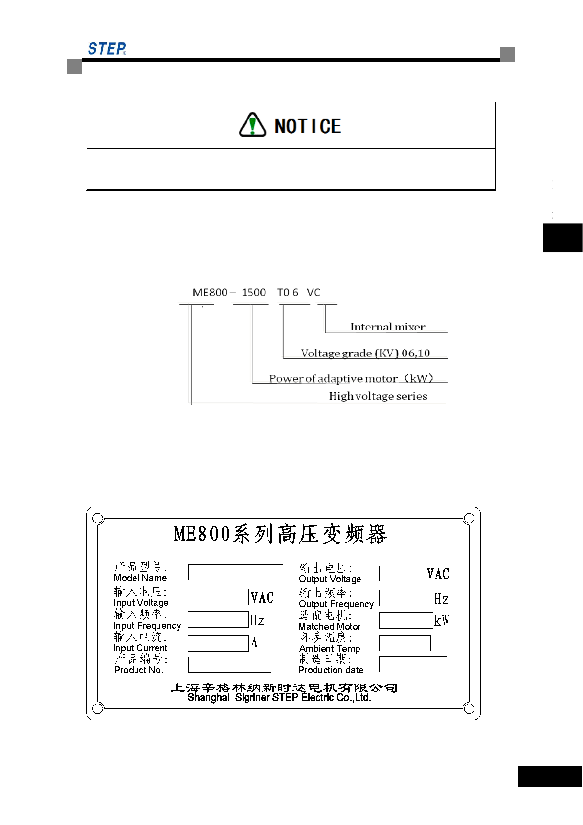
1.3 Description of inverter model
Fig.1-1 Description of inverter model
1.4 Description of inverter nameplate
For inverter nameplate, see Fig.1-2. Nameplate of inverter records inverter model,
specification, machine No and order No, etc.
Fig.1-2 Inverter nameplate

Shanghai Sigriner STEP Electric Co.,Ltd
4
1-4
Chapter Ⅰ
Notice for inverter use
1.5 Discard as useless notice
A discard as useless inverter needs to be handled as industrial refuse.
1.5.1 Capacitor handling
Electrolytic capacitors in main circuit and printed circuit board may explode while burning. It
is prohibited to burn them.
1.5.2 Plastic piece handling
There are many plastic pieces in inverter, and burning plastic piece will produce toxic gas.
Therefore, it is prohibited to burn them.

ME800 High-voltage Inverter Operation Instruction
2-1
Chapter II
Overview of Inverter
Chapter ⅡOverview of Inverter
2.1 Technical characteristics
As a new generation of high-high voltage inverter designed and manufactured by our company,
ME800 series HV inverter is able to suppress input harmonic current at the network side by the
shift-phase rectify transformer, and realize voltage overly by cascading multistage H bride
power unit, so as to obtain the perfect high voltage sine wave output. It will directly drive high
voltage motor, without any filter. ME800 series HV inverter applies to the standard high voltage
(3kV,6kV and 10kV)3-phase AC motor, with following characteristics:
2.1.1 High-quality input characteristics
ME800 series high voltage inverter applies shift-phase multiple rectification technology at the
power supply side, with small pollution to the harmonic on grid side and high power factor,
meeting GB 14549-9 and IEEE std 519-1992 in terms of voltage and current harmonic
distortion degree, without harmonic interference to other electrical equipment on the same grid,
as shown in Fig.2-1 and Fig.2-2.
Fig.2-1 Input 3-phase current wave form

Shanghai Sigriner STEP Electric Co.,Ltd
2
2-2
Chapter II
Overview of Inverter
Fig.2-2 Input 3-phase current total harmonic
2.1.2 Low output harmonic
Output side of ME800 series high voltage inverter uses phase-shift multiple pulse width
modulation technology with very small output harmonic, which is applicable to various motors
without any output filter device. Because of low output voltage distortion degree and good sine
degree of wave form, motor has low noise, small torque ripple and low heat productivity,
therefore scope of output cable length is wide.
Fig.2-3 Output current wave form of sine wave
ME800 High-voltage Inverter Operation Instruction
2-3
Chapter II
Overview of Inverter
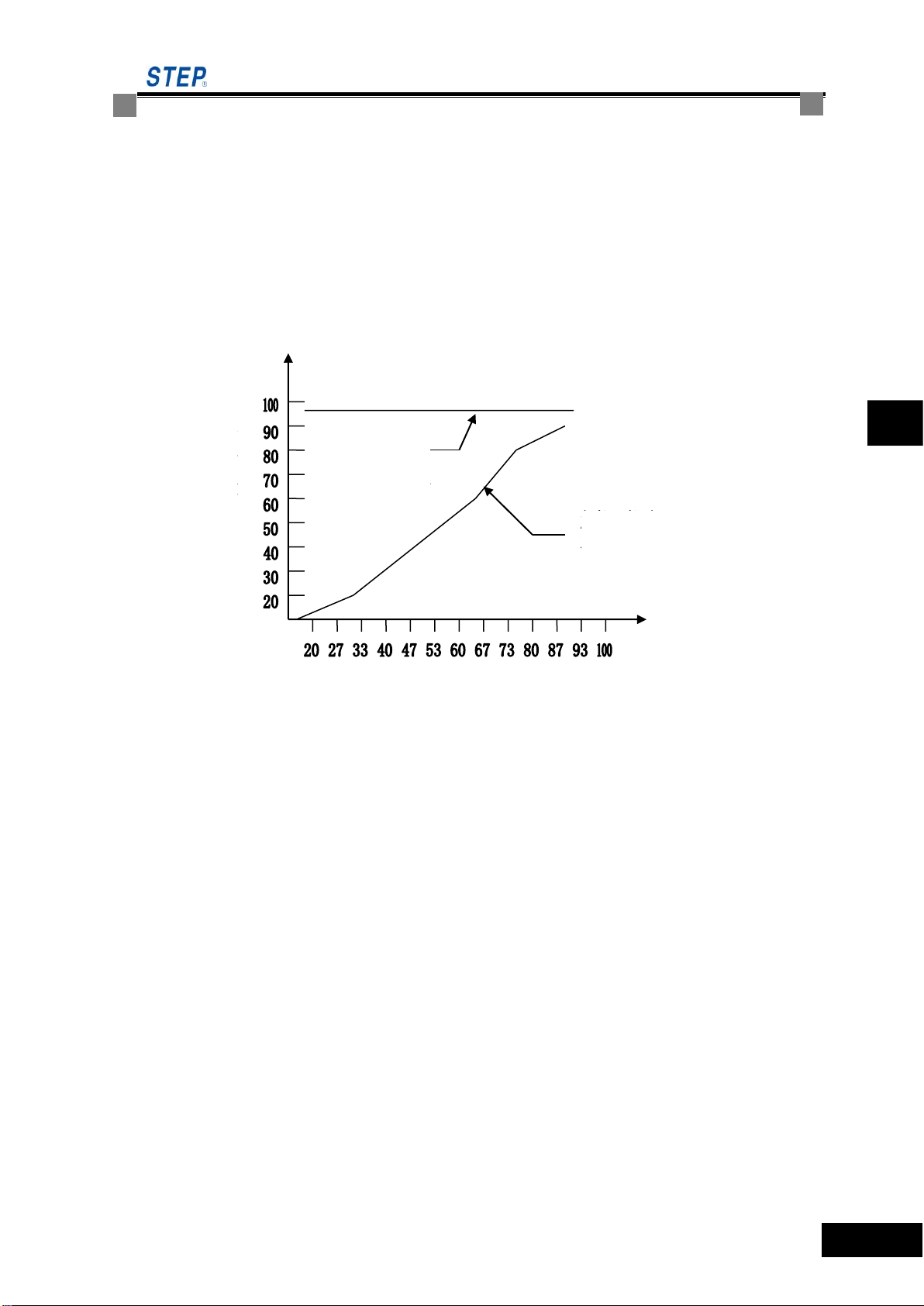
2.1.3 High power factor
ME800 series high voltage inverter belongs to the constant voltage type, which will keep high
power factor within full speed range, and its full load power factor can be over 0.95, so as to
reduce low equipment utilization rate of the user power transformer and power factor
compensation problem of the user side caused by low power factor. Fig.2-4 shows power factor
comparison between high voltage inverter and phase control thyristor.
Fig.2-4 Power factor comparison between ME800 high voltage inverter and phase control thyristor
2.1.4 Power failure and system continues to run
During system operation, the Inverter can continue to run 1.2 seconds after instant power
failure of the grid (less than 1.2 seconds). During this time the system continues to run if power
on again to avoid the loss caused by unnecessary shutdown. Beyond the time, the system will
report the fault of power outages and then shutdown.
2.1.5 High reliability and convenient maintenance
IGBT power module of ME800 high voltage inverter has bigger voltage and current design
margin, whose trigger and overcurrent protection uses the special driver module circuit with
very high reliability. Control signal of inverter is transferred via optical fiber, realizing the reliable
electrical isolation of high and low voltage weak current.
ME800 series high voltage inverter adopts modular design, with perfect structural process
design and generality for the unit module with the same capacity. If any fault occurs, the simple
tool will be used to replace it within several minutes, conveniently and quickly.
Phase control thyristor
rectification inverter
ME800 high
voltage inverter
Power factor
Percentage rate

Shanghai Sigriner STEP Electric Co.,Ltd
4
2-4
Chapter II
Overview of Inverter
2.1.6 Alarm and fault protection function
ME800 series inverter provides the perfect alarm and protection function, with the fault
message relating to power unit and the complete machine, which will be viewed via remote
monitoring interface or site operator.
If any fault appears, inverter will automatically record its operation environmental message.
2.1.7 Selection of bypass function of power unit
When any power unit of the inverter fails, bypass it through bypass function and inverter will
operate for dated capacity, to greatly improve its reliability.
Warning: Before replacing the faulty power unit, it must be shutdown and cut off the drive
high-voltage input power.
2.1.8 Selection of system variable frequency/power frequency switching
If it is required by process or high voltage inverter fails, the user can manually or automatically
realize system variable frequency/power frequency switching by choosing function parameters.
2.1.9 Soft start
ME800 series high voltage inverter has the feature of soft start. Start time is set by user, with
the built-in functions of acceleration, overcurrent and speed limit to control impact current of
motor start, guarantee safe operation of motor and lengthen its service life. Overcurrent
shock-free quick start for the grid and motor can be realized. This function also will effectively
avoid motor faults such as cage bar breakage of the motor squirrel cage.
2.1.10 Reducing motor abrasion and saving maintenance cost
Such loads as fan and pump adopt ME800 high voltage inverter to adjust output through
adjusting motor speed, which will not only reach the objective of energy conservation, but
greatly reduce mechanical wear of the motor and its load, as well as save maintenance cost for
user.
2.1.11 Rich user terminal interface
ME800 series high voltage inverter is designed with rich I/O ports for users. Users can build
specific application system with these I/O ports (4-channel analog input, 4-channel analog
output and 16-channel switching input and 8-channel relay output) supplied by system; and
partial of terminals are programmable ones, so as to guarantee good system adaptability. Users
can also expand I/O port according to the actual needs.

ME800 High-voltage Inverter Operation Instruction
2-5
Chapter II
Overview of Inverter
2.1.12 Friendly human-machine interface
ME800 series high voltage inverter human-machine interface adopts touch screen and digital
keyboard, with the rich functions of setting, display and operating, as well as friendly
human-machine interface. Users can conveniently understand the running status message of
system via human-machine interface, and control high voltage inverter as required by process
control.
2.2 Function brief
2.2.1 Frequency setting
Given way of the operation frequency:
Given by panel
Given by communication (for remote monitoring interface)
Given by analog signal input
Given by multi-speed: the inverter can set several frequency sections and acceleration &
deceleration time, with switching among these frequency sections by terminal flexibly.
Choose the relative parameters within digital multi-velocity parameter to configure the
settings relating to operation frequency; Choose selection of frequency given way by
setting frequency/speed channel selection parameter.
2.2.2 Operation Control Mode
Start mode of inverter:
Normal start;
DC braking and restart (for the fan-type load, reverse rotation may be driven by load. Firstly
hold on the motor by DC braking, and then restart it, so as to avoid the huge impact current
during start).
Speed tracking start,The inverter firstly tracks the current speed of motor, then directly
starts on the basis of current speed.
Parking mode:
Deceleration and park,control the motor speed according to deceleration curve, until it
stops after zero frequency.
Inertia parking,Directly block PWM output, the motor stops as its own inertia.

Shanghai Sigriner STEP Electric Co.,Ltd
6
2-6
Chapter II
Overview of Inverter
DC braking and parking,quick braking and parking are realized by adding DC in motor coil.
Given ways for start and parking command of inverter:
Panel control
Terminal control
Communication control
Set the given way of start and parking command by touch screen
2.2.3 Acceleration and Deceleration Protection Function
No overcurrent appears to the protection motor during the accelerating process and no
overvoltage during the decelerating process. Once overcurrent or overvoltage alarm (protection
value hasn’t been reached yet) appears, the inverter will automatically keep the current
frequency unchanged, until the voltage or current returns to the normal level and accelerate or
decorate again.
2.2.4 Frequency Hopping Function
ME800 series inverter supports to set frequency hopping, 3 frequency hopping points are
available.
Frequency hopping: in order to avoid equipment damage such as motor caused by that the
inverter run at point of resonance of mechanical equipment, users can avoid this point of
resonance by setting frequency hopping.
Frequency hopping bandwidth: frequency width, when the inverter hops frequency, shall
not be too large, for example (0.5-2), or it may cause overcurrent or overvoltage.
2.2.5 Torque Lifting Function Controlled by V/F
ME800 series high voltage speed governing system provides low frequency torque lifting
function, the user may set torque lifting amplitude and speed scope that the torque needs to lift
within user-defined V/F parameters adopting the relevant parameter.
2.2.6 Configuration of Programmable User Terminal
ME800 series high voltage inverter provides rich terminal functions for users, in addition, it may
expand these I/O terminals as the user’s actual needs. The terminals may be programmable
ones, so as to guarantee the flexible system expandability and good adaptability.

ME800 High-voltage Inverter Operation Instruction
2-7
Chapter II
Overview of Inverter
2.2.7 Real Time Monitoring Function for Operating Parameters
ME800 series high voltage inverter is of the rich parameter monitoring functions.
Operation frequency, given frequency, current speed, input voltage, output voltage, input
current, output current, running speed, output frequency, terminal status, analog value, unit bus
voltage, unit temperature, unit optical fiber communication status, unit running status, unit
bypass state transformer temperature can be monitored under all conditions.
2.2.8 Comprehensive Fault Inspection and Protection Function
ME800 series high voltage inverter provides classification protection over 220 faults, and may
automatically send an alarm or report fault treatment and record according to severity of fault.
Users may view fault message via the operator or remote monitoring interface, and the system
will provide alarm prompt interface at the same time, to avoid element damage due to serious
fault.
In addition, system provides EEPROM detection function. When EEPROM error is detected, it
will be presented to the user by remote monitoring interface.
2.2.9 Multi-level User Right Management
ME800 series high voltage inverter provides three-level user right such as visitor, operator and
administrator, and provides the related rights according to user level, making the operation
become more safe and convenient.
2.2.10 Convenient Parameter Backup Function
Remote monitoring interface provides the convenient backup function for parameters and other
configuration message, the users can restore the backup parameters into the system by means
of simple operation.
2.2.11. Communication Function
ME800 series high voltage inverter provides the external Modbus (standard configuration) and
Profibus-DP (selective configuration) communication interface. The user may control and set
inverter with his own system via protocol.
2.3 Composition and working principle of inverter
2.3.1 Composition
The standard configuration of ME800 series inverter cabinet is different, which is based on the

Shanghai Sigriner STEP Electric Co.,Ltd
8
2-8
Chapter II
Overview of Inverter
inverter, model and quantity of units as well as other factors. But it is generally composed of the
following cabinet:
Transformer cabinet
System control cabinet
Power unit cabinet
System bypass cabinet(selective configuration)
Start cabinet(selective configuration)
Fig.2-5 is the appearance of typical ME800 inverter.
Fig.2-5 Appearance of ME800 Inverter
2.3.1.1 Transformer cabinet
Transformer part of ME800 inverter mainly includes phase-shift rectification transformer and its
cabinet. Input power line enters inverter from this cabinet and output power line to motor also is
led from here. Input and output power line applies both up and down incoming line. One or
several fans are also needed to cool the transformer. See Fig.2-6.
This manual suits for next models
70
Table of contents
Other STEP Inverter manuals


