Terrasmart Tracker Interface Foundation User manual

www.terrasmart.com
© Copyright 2022, Terrasmart, Inc. All rights reserved. | 000512-001| Tracker Interface Foundation Manual | Page 1 of 9 Proprietary and confidential. The information contained in this
document is the sole property of Terrasmart. Any reproduction in part or as a whole without written permission of Terrasmart is prohibited.
Tracker Interface Foundation
Installation Manual
REV 3 DATE: MAY 2O22

www.terrasmart.com
© Copyright 2022, Terrasmart, Inc. All rights reserved. | 000512-001| Tracker Interface Foundation Manual | Page 2 of 9 Proprietary and confidential. The information contained in this
document is the sole property of Terrasmart. Any reproduction in part or as a whole without written permission of Terrasmart is prohibited.
Table of Contents
1
Tracker InterfaceFoundation Pre-Installation
...........................................................................
3
1.1
System Requirements /System Notes
....................................................................................
3
1.2
Main Parts
..................................................................................................................................
4
1.3
Parts
............................................................................................................................................
5
1.4
Hardware
....................................................................................................................................
6
2
Tracker InterfaceFoundation Installation
..................................................................................
7
3
Appendix A-1 Manufactured Assemblies
...................................................................................
9

www.terrasmart.com
© Copyright 2022, Terrasmart, Inc. All rights reserved. | 000512-001| Tracker Interface Foundation Manual | Page 3 of 9 Proprietary and confidential. The information contained in this
document is the sole property of Terrasmart. Any reproduction in part or as a whole without written permission of Terrasmart is prohibited.
1.1
SystemRequirements/DocumentNotes
Terrasmart, Inc. (Terrasmart) model Tracker Interface Foundation solar ground mounting system is
listed by CSA to UL 2703 for Bonding and Grounding.
In accordance with UL 2703, the Terrasmart Tracker Interface Foundation is intended for use with
photovoltaic module systems with a maximum system voltage of 1500 V.
Pre-Assembled Sub-Assemblies:
The mounting system may ship as individual components or subassemblies from the factory and is field
assembled. Factory sub-assemblies must be checked for component alignment and connection
requirements must be verified. Some bolted sub assemblies may also ship with additional optional
welded connections for added mechanical or structural strength.
Corrasion Protection:
All components on the Terrasmart Tracker Interface are G90 galvanized minimum or hot dip galvanized
in accordance with UL 2703.
Bonding and Grounding:
The components within the Terrasmart Tracker Interface Foundation system are bonded to each other in
accordance with UL 2703. The Terrasmart Tracker Interface Foundation system must be bonded to the
tracker system in accordance with the
National Electrical Code (NEC).
After Installation:
Periodic inspections of the mountingsystem should be performed. Continued maintenance by qualified
persons shall include the following: Any loose components or fasteners shall be re-tightened in
accordance with these instructions.Any
components showing signs of damage that compromise safety shall be replaced.

www.terrasmart.com
© Copyright 2022, Terrasmart, Inc. All rights reserved. | 000512-001| Tracker Interface Foundation Manual | Page 4 of 9 Proprietary and confidential. The information contained in this
document is the sole property of Terrasmart. Any reproduction in part or as a whole without written permission of Terrasmart is prohibited.
MAIN PARTS
VIEW
DESCRIPTION
LOCATION
VERTICAL SUPPORT - W-BEAM
TOP OF ASSEMBLY CONNECTS TO
TRACKING SYSTEM
E/W SUPPORT BEAM - SQUARE HSS BEAM
MIDDLE OF ASSEMBLY ATTACHED TO
LEGS AND VERTICAL SUPPORT BEAM
TOP CONNECTIONS
BASE OF ASSEMBLY INSERTED
LEG TUBE
IN GROUND SCREW
ATTACHED TO E/W SUPPORT SQUARE
HSS BEAM
DETAIL OF TOP
CONNECTIONS
ANGLE BRACKET
ATTACHES VERTICAL SUPPORT
BEAM TO E/W SUPPORT SQUAREHSS
BEAM
LEG TUBE BRACKET
ATTACHES LEG TO E/W SUPPORT
SQUARE HSS BEAM

www.terrasmart.com
© Copyright 2022, Terrasmart, Inc. All rights reserved. | 000512-001| Tracker Interface Foundation Manual | Page 5 of 9 Proprietary and confidential. The information contained in this
document is the sole property of Terrasmart. Any reproduction in part or as a whole without written permission of Terrasmart is prohibited.
PARTS
VIEW
DESCRIPTION
LOCATION
INTERLOCKING BRACE CLAMP
ATTACHES LATERAL BRACES TO LEG
TUBES
EXTERNAL LATERAL BRACE
ATTACHES NEAR THE TOP OF LEG
BRACKET ON THE LEG
INTERNAL LATERAL BRACE
ATTACHES NEAR THE GROUND SCREW
ON THE LEG
GROUND SCREW ASSEMBLY
SCREWS IN GROUND FOR SUPPORT AND
HAS LEG TUBE INSERTED
GROUND SCREW SET BOLT
M16x2x25 HEX BOLT
USE TO TORQUE LEG TUBE FROM
GROUND SCREW - TORQUE:FLUSH
WITH WELD NUT

© Copyright 2022, Terrasmart, Inc. All rights reserved. | 000512-001| Tracker Interface Foundation Manual | Page 6 of 9 Proprietary and confidential. The information contained in this
document is the sole property of Terrasmart. Any reproduction in part or as a whole without written permission of Terrasmart is prohibited.
HARDWARE
VIEW
DESCRIPTION
TORQUE
1/2"-13 x 1 1/2" CARRIAGE BOLT
(VERTICAL W-BEAM TO ANGLE
BRACKET)
(LEG BRACKET TO SQUARE HSSBEAM)
64 FT-LBS
1/2"-13 x 3 1/2" CARRIAGE BOLT
(LEG TUBE TO LEG BRACKET)
64 FT-LBS
1/2"-13 x 5" CARRIAGE BOLT
(VERTICAL BEAM ANGLE BRACKETTO
SQUARE HSS BEAM)
64 FT-LBS
1/2" - 13 SERRATED FLANGE NUT
64 FT-LBS
3/8"-16 x 1 1/2" CARRIAGE BOLT
(INTERLOCKING BRACE CLAMP)
26 FT-LBS
3/8"-16 x 3" CARRIAGE BOLT
(LATERAL TO LATERAL)
26 FT-LBS
3/8" - 16 SERRATED FLANGE NUT
26 FT-LBS
www.terrasmart.com
© Copyright 2022, Terrasmart, Inc. All rights reserved. | 000512-001| Tracker Interface Foundation Manual | Page 7 of 9 Proprietary and confidential. The information contained in this
document is the sole property of Terrasmart. Any reproduction in part or as a whole without written permission of Terrasmart is prohibited.
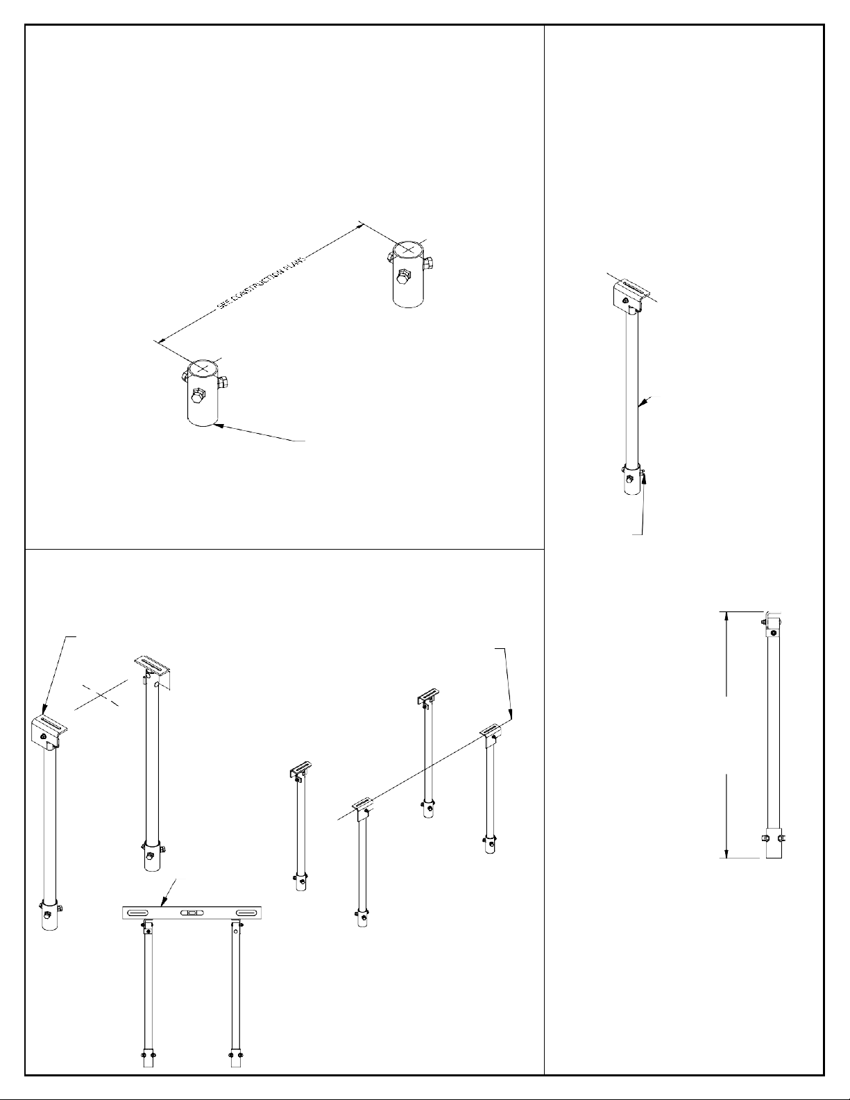
SURVEY
HEIGHT
STEP 1: VERIFY GROUND SCREW LOCATION & SPACING, GROUND SCREW
ARE TO BE INSTALLED WITHIN 2 INCHES OF SURVEYED POINT
STEP 2: USING SETBOLTS INSERT AND
SET
LEGS TO PREDETERMINED HEIGHT, TOP
BRACKET SLOT POINTS NORTH/SOUTH
DIRECTION. ONCE INSTALLED TORQUE
THE SET BOLT SO THAT IT IS FLUSH WITH
THE WELD NUT ON THE GROUND SCREW
N
S
INSERT LEG INTO
GROUND SCREW
GROUND SCREW
HEAD FROM GRADE
**NOTE GROUND SCREW TOLERANCES ARE ±2" FROM SURVEY POINT
USE SET BOLTS
TO LOCK LEGS
STEP 3: INSTALL LEGS IN PAIRS. HEIGHTS SHOULD ACCOUNT FOR GRADE.
SLOTS SHOULD RUN NORTH/SOUTH. USE A LEVEL ON TOP OF LEG BRACKET
TO VERIFY THAT LEGS ARE INSTALLED LEVEL WITH EACH OTHER.
ENSURE TOP BRACKET
PAIRS ARE LEVEL LASER LEVELOR
STRING LINE FROM
LEG SET TO LEG SET
N E
S
W
USE LEVEL TOSET
TOLERANCE OF 1°
BETWEENLEGS
ONCE FINAL
DESIRED HEIGHT
IS OBTAINED
www.terrasmart.com
© Copyright 2022, Terrasmart, Inc. All rights reserved. | 000512-001| Tracker Interface Foundation Manual | Page 8 of 9 Proprietary and confidential. The information contained in this
document is the sole property of Terrasmart. Any reproduction in part or as a whole without written permission of Terrasmart is prohibited.
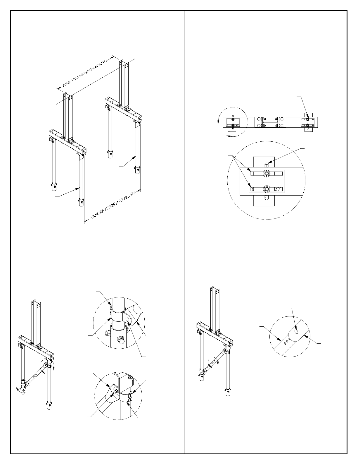
STEP 4: PLACE W-BEAMS ON TOP OF LEGS, ADJUST PIERS TO BE
FLUSH WITH THE SQUARE HSS TUBE IN THE EAST WEST
DIRECTION (REFER TO PLANS FOR NORTH SOUTH SPACING)
ADJUST TEE TO ± 1/2"
FROM STRING LINEOR
LASER LEVEL.
BEARING PIER
BEARING PIER
STEP 5: USE THE COMBINATION OF THE SLOTS TO ADJUST
THE PIERS WITH RESPECT TO EACH OTHER. THE DIAGRAM
IN STEP 4 DICTATES THE IDEAL SLOT CONNECTION.
TORQUE TO 64 FT-LBS
WHEN IN POSITION
USE SLOT FOR
USE SLOTS FOR N-SADJUSTABILITY
E-W ADJUSTABILITY
STEP 6: INSTALL BRACE CLAMP AROUND LEG. BOLT LATERAL
BRACE BETWEEN THE CLAMP HALVES AND BOLT.
STEP 7: INSERT INTERNAL INSIDE EXTERNAL AND ALIGN
WITH BRACE CLAMPS. BOLT THE LATERAL BRACE CLAMPS
USING 3/8" HARDWARE. LOCK THE LATERAL BRACE USING
** REFER TO LATERAL PLAN DRAWING DETAILS BELOW FOR
THE 3/8"x3" BOLT. TORQUE ALL 3/8" HARDWARE TO 26
CLAMP PLACEMENT
FT-LBS.
MAX 6" FROM TOP
OF GROUND SCREW
3/8" x 3" BOLT
INTERNAL
BRACE CLAMP LATERAL
LATERAL
BRACE
BRACE
EXTERNAL
LATERAL
3/8" x 1 1/2"
BRACE
BOLT
F LATERAL
BRACE
BRACE CLAMP
**NOTE: LATERAL BRACES ARE DESIGNED TO ALLOW FOR 7" OF TOTAL ADJUSTMENT.
IF FIELD CONDITIONS REQUIRE ADDITIONAL ADJUSTMENT AND LATERAL BRACES
3/8" x 1 1/2"
MAX 6" FROM BASE
BOLT OF LEG BRACKET
ARE TOO LONG, THEY MAY BE CUT DOWN AND DRILLED TO FIT BY THE RACK
INSTALLER. IF THEY ARE TOO SHORT, NEW LATERAL BRACES MAYBE ORDERED
TO FIT AT PURCHASER'S EXPENSE.
www.terrasmart.com

© Copyright 2022, Terrasmart, Inc. All rights reserved. | 000512-001| Tracker Interface Foundation Manual | Page 9 of 9 Proprietary and confidential. The information contained in this
document is the sole property of Terrasmart. Any reproduction in part or as a whole without written permission of Terrasmart is prohibited.
APPENDIX A-1
ANGLE BRACKET
1/2"-13 x 1 1/2" CARRIAGE BOLT
TORQUE: 64 FT/LBS
1/2"-13 x 5" CARRIAGE BOLT
TORQUE: 64 FT/LBS
MANUFACTURED PIER
ASSEMBLY
1/2"-13 x 3 1/2" CARRIAGE BOLT
TORQUE: 64 FT/LBS
LEG BRACKET
1/2"-13 x 3 1/2" CARRIAGE BOLT
TORQUE: 64 FT/LBS
MANUFACTURED LEG
ASSEMBLY
www.terrasmart.com
Table of contents
Other Terrasmart Inverter manuals

Popular Inverter manuals by other brands


BYGD
BYGD SW2000 user manual

Samlexpower
Samlexpower PST-120-12 owner's manual

Marecoluce
Marecoluce Stud Solar user manual

hpmont
hpmont HD31-4T2P2P user manual

Sumitomo Drive Technologies
Sumitomo Drive Technologies SI-485/J-H Technical manual

Victron energy
Victron energy MultiPlus 12/5000/200-100 230V user manual