Stephan VCM 44 User manual


31.10.2002 \\Docuserver\ba\UM\Aktueller_Auftrag_UM044_60\UM_A+S44_60_englIVZ.fm Machine-No.see cover 1
Table of contents Machine-No.see cover
VCM 44
Table of contents page
1. Safety instructions .............................................................................................. 3
1.1 Correct usage.................................................................................................................. 3
1.2 Explanation of symbols and signs................................................................................... 3
1.3 General working safety.................................................................................................... 4
1.4 Operation......................................................................................................................... 4
1.5 Maintenance and repairs................................................................................................. 5
1.6 Service and guarantee .................................................................................................... 5
2. Preface .................................................................................................................. 7
2.1 Please bear in mind the following points: ....................................................................... 7
3. Technical data ...................................................................................................... 8
3.1 Machine Data ................................................................................................................. 9
3.2 Energy consumption........................................................................................................ 9
3.3 Electric............................................................................................................................. 9
3.4 Dimensional drawing VCM 44......................................................................................... 9
3.5 Area of application and intended usage ....................................................................... 10
3.6 Summary ...................................................................................................................... 10
4. Set-up and starting ............................................................................................ 11
4.1 Rotational direction check ............................................................................................. 11
4.2 Function testing and test run......................................................................................... 11
5. Operating the machine ...................................................................................... 13
5.1 Working insert fitting...................................................................................................... 13
5.2 Loading the machine..................................................................................................... 13
5.3 The electronic timer SX 200.......................................................................................... 13
5.4 Mechanical product treatment. ..................................................................................... 15
5.5 Discharging the machine............................................................................................... 15
6. Daily cleaning and maintenance ...................................................................... 16
6.1 Cleaning procedure....................................................................................................... 16
6.2 Maintenance work for 8 hour operation Maintenance work........................................... 17
7. Machine description .......................................................................................... 18
7.1 Motors .......................................................................................................................... 18
7.2 Working inserts.............................................................................................................. 18
7.3 Bowl .............................................................................................................................. 21
7.4 Safety features ............................................................................................................. 21

31.10.2002 \\Docuserver\ba\UM\Aktueller_Auftrag_UM044_60\UM_A+S44_60_englIVZ.fm Machine-No.see cover 2
Table of contents Machine-No.see cover
VCM 44
Table of contents page
7.5 Electronic equipment..................................................................................................... 21
8. Fault repair ......................................................................................................... 22
8.1 Faults in the drive motors .............................................................................................. 22
8.2 Faults in the electronic equipment................................................................................. 23
9. Maintenance ........................................................................................................ 24
9.1 Sharpening the blades ................................................................................................. 24
9.2 Changing the seals........................................................................................................ 24
10. Cleaning and disinfection ................................................................................. 26
10.1 Stages of the cleaning and disinfection process .......................................................... 26
10.2 Disinfection ................................................................................................................... 27
11. Replacement and spare parts ........................................................................... 29
11.1 Stand for US execution ................................................................................................. 30
11.2 Bowl, standard............................................................................................................... 32
11.3 Lid, standard.................................................................................................................. 34
11.4 Working inserts.............................................................................................................. 35
11.5 Motor type 132, 2 speed................................................................................................ 37
11.6 Electrical equipment VCM 44........................................................................................ 38
12. Serviceadressen / Service adresses / Adresse du SAV................................. 39
Index .................................................................................................................... 40

31.10.2002 3
Safety instructions
1. Safety instructions
STEPHAN machines are constructed for effective and safe use in the food and processing in-
dustry.
Conditions for the successful and safe operation of these machines are that:
· The machine is installed and commissioned only by appropriately trained personnel.
· The enclosed operation and maintenance instructions for the machine are followed exactly
and maintained under all circumstances.
· Any person working with the machine should be thoroughly acquainted with the health and
safety instructions.
1.1 Correct usage
· STEPHAN machines are intended for mechanical and industrial manufacture of products ac-
cording to the procedures indicated and the specifications detailed for the machine and periph-
eral equipment supplied.
the following are not permitted:
· Operation and maintenance of the machine by unauthorised and not properly trained person-
nel.
· Inappropriate or improper use of the machine.
· Alteration of safety devices such as switches, locks, covers, guards, seals etc., or making
them inoperative.
· Contravention of local safety and accident prevention regulations.
1.2 Explanation of symbols and signs
A number of signs are used in these operating instructions which must be observed under all
circumstances in order to avoid risks to personnel and machines.
These signs have the following symbols:
DANGER
Sign which, when ignored, can lead to injury.
WARNING
Sign which, when ignored, can lead to damage to the machine.
NOTE
Notes and advice on working with the machine.

31.10.2002 4
Safety instructions
1.3 General working safety
Improper operation of the machine can lead to personal injury, damage to the machine and
interruptions to the production process.
The management responsible must therefore ensure that operating personnel are properly
trained and that only qualified and authorised personnel work on machine.
1.4 Operation
Operators must be thoroughly trained in handling the machine and its processes.
SAFETY LOCKING DEVICES
Mechanical and electrical safety devices located on the cover and in the discharging
and emptying area prevent anyone from reaching into the machine while it is run-
ning. These safety devices must under no circumstances be made inoperative.
OILS, LUBRICANTS AND COOLANTS
Some of these agents endanger personal health and the environment. Only materi-
als recognised as being physiologically safe should be used. Selection and use of
these materials depends entirely on the management, although STEPHAN can
make recommendations with respect to the materials used.
PRESSURE VESSEL REGULATIONS
If pressure vessels are installed, they are subject to regular inspections according to
the pressure vessel regulations. If necessary, the vessel may need to be tested in
the location where the machine is to be installed. All inspection certificates must be
stored carefully. All working and inspection instructions in the pressure vessel regu-
lations must be observed.
SAFETY VALVE
If the STEPHAN machine works with overpressure, the safety valve is protected in
the works so that the permissible pressure cannot be exceeded. The valve is fitted
with a lead seal so that the release pressure cannot be adjusted. Manipulating the
valve can lead to fatal injuries. Removal of the lead seal also invalidates the guar-
antee.Material drained from the safety valve must be disposed of properly and safe-
ly.
SAFETY AWARENESS
- Management must ensure that operating and maintenance personnel are thor-
oughly acquainted with all safety instructions and that all safety instructions are ac-
tually observed. The operating instructions should be readily available for reference
in the workplace.
- All working procedures which reduce safety at the machine must be avoided.
- Operators are obliged to announce at once every alteration to the machine which
reduces its safety.
- The machine's safety can be reduced by:
* reconfiguration or alteration of the machine
* use of accessories other than those provided by STEPHAN- use of non-original re-
placement and wearing parts
CONCEALED KNIVES, CUTTING RINGS, FEED SCREWS, ETC.
Do not reach into full or partially full machine bowls or funnels, as there is risk of in-
jury from concealed sharp-edged cutting tools and machine parts.

31.10.2002 5
Safety instructions
1.5 Maintenance and repairs
All maintenance and repair work may only be carried out by specially trained personnel..
1.6 Service and guarantee
TECHNICAL LIMITING VALUES
Observe the limiting values for the technical machine data specified.
PLACING THE MACHINE OUT OF OPERATION
- Switch off the main switch before maintenance and repair work to prevent it from
being switched on inadvertently. This applies to all work on the switch cabinet and
peripheral units.
- For steam installations the steam supply must be switched off and must be secured
before re-starting. The machine and all pipelines must be depressurised.
- For hydraulic systems with an accumulator the system must be depressurised at
the accumulator release valve.
- For pneumatic systems, the system must be depressurised and the stop valve
closed.
ELECTRIC SYSTEMS
All electrical work must only be carried out by qualified electricians. The general and
specific accident prevention regulations must be observed during electrical repair
work.
SAFETY DEVICES
When dismantling safety devices for repair and maintenance work, the machine
must be placed out of operation. The safety devices must be connected again im-
mediately after completion of repair and maintenance work and checked for perfect
operation.
COMMISSIONING
The operation of the safety devices must be checked before commissioning the ma-
chine.
It should be checked that the work tools are properly attached and that there are no
foreign bodies in the machine, as loose parts in the machine can damage the work
tools and motor shaft
MOTOR PROTECTION IP 54 AND SWITCH CABINET PROTECTION IP54
Washing the motor or switch cabinet with pressurised water or cleaning agent is not
permitted.
INVALIDATION OF GUARANTEESTEPHAN
will accept no responsibility or guarantee claims for damage caused by:
· not observing the operating instructions,
· improper operation and maintenance of the machine and its peripheral equipment,
· technical and functional modifications carried out without consulting STEPHAN,
· use of parts other than original STEPHAN parts and accessories,
· disconnecting, dismounting or otherwise making safety devices inoperative.

31.10.2002 6
Safety instructions
REPLACEMENT PARTS
A stock of the most important replacement and wearing parts at the machine's loca-
tion is important for its continual operation.
ORDERING REPLACEMENT PARTS
STEPHAN require the following information to process replacement parts orders:
· machine type from the cover of the operating instructions
· machine number from the machine type plate[e.g. K 720.000]
· order numberin the replacement parts list in the operating instructions
This information avoids the need for any further questions from our Service Depart-
ment and speeds up delivery.
We will be pleased to assist you with any questions on your machine
A. Stephan und Söhne GmbH & Co.
Serviceabteilung Stephanplatz 2 31789 Hameln
Telephon: 05151/5830 Fax: 05151/583110

31.10.2002 \\Docuserver\ba\UM\Aktueller_Auftrag_UM044_60\Starte.fm 7
VCM 44
2. Preface
The VCM 44 is a robust and durable multipurpose machine for the food production industry
and food production technology, that is to say, this machine type may be used in almost all
areas of food production, depending on configuration.
Described variants which are not part of your machine have not been ordered and / or are not
required for your product.
Should you have questions about your machine or the equipment which are not answered by
this operating manual, or wish to enquire about the manufacture of a particular product, please
get in touch with one of our technical advisors for your technical area:
Stephan Machinery Corp.
7200 Alum Creek Drive
Suite I
Columbus/Ohio 43217-1349
001 / 614 / 497-8951
001 / 614 / 497-9123
or get in touch with one of our dealers. (See ” Serviceadressen / Service adresses / Adresse
du SAV” on page 39.)
2.1 Please bear in mind the following points:
This operating manual is intended to be read, understood and followed in every detail by those
who are responsible for, and work with, the VCM 44
In particular, the general safety precautions on the colored pages at the front should be ob-
served.
The complete documentation should always be kept at the place of installation of the VCM 44.
Only with full knowledge of the operating manual can mistakes of the multipurpose machine
be prevented and a trouble-free operation guaranteed. Thus it is most important that the re-
sponsible persons are really familiar with this operating manual.
Please read these operating instructions through thoroughly before starting the machine, as
we accept no liability for damage and operating errors which result from the non-observation
of these operating instructions.
If, however, problems should ever arise, please get in touch with our customer service and
spares department or with one of our dealers, who will gladly assist you (see address list on
last page).
These operating instructions apply only to the product range VCM 44

Technical data
31.10.2002 \\Docuserver\ba\UM\Aktueller_Auftrag_UM044_60\Starte.fm 8
VCM 44
3. Technical data
Machine-type VCM 44
Customer
Comm.-no. Machine-No.see cover
Wiring-diagram-no. See sticker in the cabinet
Year of construction 2002

Technical data
31.10.2002 \\Docuserver\ba\UM\Aktueller_Auftrag_UM044_60\Starte.fm 9
VCM 44
3.1 Machine Data
3.2 Energy consumption
3.3 Electric
3.4 Dimensional drawing VCM 44
Bowl capacity (to bowl rim) l ca. 45
Load size (depending on product) l max. 30
Machine weight (net) kg
Max. permissible operating excess pressure in bowl bar
PSI 0.0
0.0
Max. permissible operating temperature in bowl °C / °F 95 / 203
Main motor type 132 S-4/2 n at 60 Hz = 1800/3600 kW 5.5/7.5
Supply voltage / frequency V / Hz 220/ 60
Control voltage V 110 DC
Fuse protection at 220 V (slow-blow) A 35
800 525
912
1120
575
310
1200
1500
1395
532

Technical data
31.10.2002 \\Docuserver\ba\UM\Aktueller_Auftrag_UM044_60\Starte.fm 10
VCM 44
3.5 Area of application and intended usage
The VCM 44 isexclusivelydesigned forthe mixing,chopping, cutting,slicing, kneading offood
products.
The Motor performance and the working inserts must be compatible with the process and the
product to be processed; the technical limit values of the machine should not be exceeded.
(See ” Machine Data” on page 9.)
3.6 Summary
The VCM 44 is a multipurpose machine for the manufacture of food products. It combines high
performance with attractive design in the most compact form. It conforms to the most modern
hygiene regulations.
All parts coming into contact with the product consist of non-rust stainless steel or other phys-
iologically harmless materials.
The process container with the direct-driven working inserts is swivel-mounted on the machine
base; bowl tipping and lid opening are performed by hand operation.
The following machine functions are available:
Any use beyond this is not regarded as normal use. The manufacturer will not be
liable for resulting damage. The user only will bear the risk.
Loading manually via opened lid
Processes Mixing, chopping, slicing, cutting, emulsifying, kneading
Emptying manually via opened lid by tipping the container
Control manually via pushbuttons.

Set-up and starting
31.10.2002 \\Docuserver\ba\Master\Ba_eng\UM\044_60\UM_A+S\Inbetr.fm 11
VCM 44
4. Set-up and starting
4.1 Rotational direction check
The direction of rotation check has already been carried out during test running before the de-
livery of the VCM 44. Should, on new installation, a drive have a direction of rotation different
to that given in the table below, the polarity of the phase supply must be reversed.
The motor connections are only to be altered if, after the replacement of a motor, gear or pump,
the direction of rotation requires correction according to the following table.
To check rotational direction, disconnect the working insert from the main motor shaft, close
and lock the lid. Only start individual drives for a short time. In the following table, rotational
direction is always with respect to the view from above the machine.
4.2 Function testing and test run
The basic functions of theVCM 44 have been factory tested. In order to ensure, however, that
no damage has arisen during transport or installation, a test run of the machine should be car-
ried out shortly after its setting-up.
What to do first.. ...and then carry out and double check!
Due to its own weight and low-vibration operation, the
multi-purpose machine may be installed without addi-
tional fastening.
However, it requires a firm surface to stand on.
Before starting up, you should check that the supply
voltage conforms to the operating voltage specified on
the VCM 44rating plate. The stipulated fuse protection
must be provided.
All electrical work is only to be carried out by a
qualified electrician.
Remove all loose parts from the machine. Loose parts flying about in the machine may dam-
age the working inserts and the motor shaft.
All electrical work is only to be carried out by a qualified electrician.
Drive Where to test? Direction of rotation Arrow towards
Mainmotor Spin plate beneath the bowl floor Towards the right End shield

Set-up and starting
31.10.2002 \\Docuserver\ba\Master\Ba_eng\UM\044_60\UM_A+S\Inbetr.fm 12
VCM 44
We emphasis once more that only persons properly familiar with the functioning of the machine
are permitted to operate the VCM 44
What to do first.. ...and then carry out and double check!
Attach the cutting insert to the tool holder of the ma-
chine base with the wing nut pointing upwards and en-
surethat thenutistight.Ifnecessary,tightenfirmly with
the open-end spanner supplied.
The knives must be absolutely securely mounted.
The slanting edge of the blade must be towards the
bowl base to obtain optimal circulation of the mate-
rial.
Three quarters fill the bowl with warm water (ca. 50°C
/ 122°F). The VCM 44requires headroom for perfect product
processing, i.e., the bowl must not be filled beyond
3/4 capacity.
Close the lid and lock the toggle seal.
Switch on main motor.
Allow the machine to run for five minutes.
Unlock the toggle seal and then open the lid.
Tip and empty the container. Wait until the contents of the bowl are stationary to
avoid the danger of splashing.
Always wear protective safety gloves if surfaces are
hot.
I

Operating the machine
31.10.2002 \\Docuserver\ba\Master\Ba_eng\UM\044_60\UM_A+S\Bedien.fm 13
VCM 44
5. Operating the machine
5.1 Working insert fitting
5.2 Loading the machine.
5.3 The electronic timer SX 200
The built in timer is a microprocessor based digital timer housed in a standard DIN style case
with a 72 mm (2.83 inch) square front bezel and a .3 inch high LED display.
The programmable features of the timer include eight time ranges and eight output operating
modes. These operating modes, and all other set-up functions are programmed with miniature
rocker switches located on the back of the housing.
Caution! Danger of injury when handling sharp blades and working inserts.
What should happen What to do Key The result!
Open container Unlock toggle seal
Open lid. Lid is open
Working inserts fitting Pull the tool carefully over the motor
shaft and turn clockwise to secure it.
Remounting is done vice-versa.
workinginsertsare readyforuse.
The VCM 44 requires headroom for perfect product processing, i.e., the bowl must
not be filled beyond 3/4 capacity.
What should happen What to do Key The result!
Manual loading Unlock toggle seals
Open lid. Lid is open
Put in product.
Close container Close the lid and lock the toggle seal.
Themachine is ready to process.
Manualmeasuring via opened
sight glass. Open sight glass. Fill in ingredients

Operating the machine
31.10.2002 \\Docuserver\ba\Master\Ba_eng\UM\044_60\UM_A+S\Bedien.fm 14
VCM 44
5.3.1 Entering and Display Setpoints
To create or change a setpoint, press the set key. The display will either show zeros or the set
point (if one exist) in memory. The other keys will also be active.
When the set key is pressed, the display will show the least significant digit at the right of the
display flashing in cursor fashion. The flashing digit is the one which can be changed using the
up and down keys.
Pressing the position key moves the position of the flashing cursor digit to the left so thatany
digit can be changed individually. The flashing cursor digit will return to the far right position if
the position key is pressed repeatedly.
The flashing cursor digit can be changed by pressing the up and down keys.
Pressing the up and down keys changes the display digit once per key actuation. if the up and
down key are held continuously, the display digits will change every .5 second until the key is
released.
When the desired setpoint is displayed, press the ent key. The new setpoint will be entered
into memory, and the up and down keys will become inoperative.
If the unit is in the reset or timed out states, the display will show either zeros or the setpoint
value depending on programming.
If the unit is in the timing mode the display will show the actual time value. If a new setpoint
has been entered while the unit is in the timing or timed out operating states, the new setpoint
will not become effective until the unit is reset.
The setpoint may be displayed at any time without disturbing the timing operation by pressing
the set key.
1. 8-digit LED-display
2. LED annunciator steady on when programmed
contacts are energized
3. LED annunciator flashes when timing, steady on
when timed out.
4. Position key
5. Marking surface
6. Up- and down key to set the terms.
7. Set key
8. Enter key
If the unit is operating when the set key is pressed, the timing operation and outputs
are not affected.
Note that the display changes will carry to the digit on the left on 9 to 0 transitions
using the up key.
The display will substract from the digits on the left on the 0 to 9 transitions when
using the down key.
Ontime ranges7 and8,the displaywill carryon the59to 00transitions andsubtract
on the 00 to 59 transition.
3
5
2
6
8
1
7
4

Operating the machine
31.10.2002 \\Docuserver\ba\Master\Ba_eng\UM\044_60\UM_A+S\Bedien.fm 15
VCM 44
5.3.2 Keypad Lock
The timer has a keypad lock function accessible on the front panel.
To actuate the lock, make sure that the display shows the actual value, then press and hold
the ent key for 5 seconds.
The setpoint and pulse lenght value can be displayed while the keypad is locked by using the
set key as dicribed previously.
When either of these setpoints is displayed with the keypad lock on, the least significant digit
at the right of the display will flash in cursor fashion. However, the keypad lock disables the
position, up and down keys so that no changes can be made.
To unlock the keypad, make sure the display is showing the actual value, then press and hold
the the ent key for 5 seconds.
5.4 Mechanical product treatment.
5.5 Discharging the machine
What should happen What to do Key The result!
Process product mechanically, i.e.
slice, cut, mix, stir, emulsify, etc. Switch on main motor
Turn mixing baffle slowly clockwise manual Product circulates to the
working insert
If work is done under pressure or vacuum conditions you must equalize pressure via
the aeration valve. Check the vacuum manometer to ensure that the machine is no
longer under pressure before opening the machine lid.
What should happen What to do Key The result!
Manual discharging via opened lid. Unlock toggle seal
Open lid
Tip container manual
Remove remains with a spatula. Watch out for hidden
knives.
I

Daily cleaning and maintenance
31.10.2002 \\Docuserver\ba\Master\Ba_eng\UM\044_60\UM_A+S\Tglrein.fm 16
VCM 44
6. Daily cleaning and maintenance
After production has been ended, cleaning the VCM 44 should should restore it to a germ-free
condition ready for use. The frequency and intensity of cleaning and disinfection required de-
pend fundamentally on the degree of contamination arising from the production process.
6.1 Cleaning procedure
Cleaning may be carried out manually with scrubbing brushes or with the assistance of ma-
chine functions according to the following table. High pressure hoses should not be used.
Cleaning, disinfection and sterilization are basic requirements of every process in
the food production industry and technology. Additionally, thorough cleaning ex-
tends the life of the machine and in particular the seals considerably. Complete in-
structionsfor thecleaning anddisinfection processesare tobe foundin thetechnical
appendix. (See ” Cleaning and disinfection” on page 26.)
What to do first.. ...and then carry out and double check!
Fill bowl to 2/3 full with warm water and add neutral
detergent with disinfectant action.
.
Fatty contamination is removed by water tempera-
tures over the melting point of fat (50°C).
Close and lock lid.
Turn mixing baffle slowly clockwise.
Switch on main motor at low revs. to start with and
then run for ca. 2-3 minutes at highest speed. During the removal of protein-containing dirt with wa-
ter over 60°C, coagulated protein may burn in on sur-
faces and should therefore quickly be removed with
the appropriate cleaning materials.
Open toggle seal, open lid, tip and empty bowl.
Rinse with clean water. manual Wait until the cleaning water has come to rest to avoid
splash danger.
Remove working insert from the motor shaft and
clean working inserts separately.
Clean the drill holes of the working insert should be
cleaned with a bottle brush.
Remove lid seal from the lid nut, clean and replace.
Take care when handling blades and working inserts.
Never put bare hands into a full bowl. Concealed
blades carry a high risk of cuts and injury.
Lacquered machine parts should be cleaned with a
sponge and mild soapy water. Never spray down motor, motor casing, switching
cabinet etc., with water or cleaning solutions.
Use only a dry cloth to clean the electric equipment. Electric equipment should only ever be cleaned dryly.
I

Daily cleaning and maintenance
31.10.2002 \\Docuserver\ba\Master\Ba_eng\UM\044_60\UM_A+S\Tglrein.fm 17
VCM 44
6.2 Maintenance work for 8 hour operation Maintenance work
When? Where? What to check... ...and what to do. Page
Daily Shaft seals of the bowl/motor Sight control of leakage once
daily and after every cleaning 24
Bowl and lid Seals and running sleeves in the bowl replace damaged seals
clean running sleeves and re-
placethem if wear is noticeable
on the upper surface.
24
working in-
serts
working inserts must be sharp and un-
damaged, if not, they should be replaced.
Blades should be sharpened.
(See ” Sharpening the blades”
on page 24.)
19

Machine description
31.10.2002 \\Docuserver\ba\Master\Ba_eng\UM\044_60\UM_A+S\Beschr.fm 18
VCM 44
7. Machine description
All parts of the VCM 44 which come into contact with food products are of non-rust stainless
steel or other physiologically harmless material.
7.1 Motors
7.1.1 Main Motor
The main motor is a high-performance motor with a F/H insulation.
Themain motoris directlyflanged belowthe bowl.The processinginsert isfitted ontothe motor
shaft and is locked in place by turning- like a bayonet locking.
The motor bearing shield B is designed as a counterweight to achieve a weight balance be-
tween bowl and main motor.
7.1.2 Shaft sealing of the main motor
The sealing of the main motor shaft is done by means of an integral seal system with two radial
shaft seals (vacuum and pressure).
Axial immobilization is by means of 2 thread bolts with nuts.
7.1.3 Mixing baffle
The manual moved mixing baffle promotes product circulation and scrapes the bowl and lid
clean.
7.2 Working inserts
The working inserts are manufactured from highly resistant alloyed stainless steel. Their form
and size are optimally suited to the motor performance, bowl shape and the process to be car-
ried out.
The The motor shaft may be damaged if the main motor is switched on when working in-
serts or foreign bodies are in the machine. The use of force may damage the motor
shaft and should therefore be avoided.
Only the use of a completely undamaged sealing flange guarantees a perfect ad-
justabled bowl seal. A faulty seal must be replaced immediately, since it may dam-
age the main motor. (See ” Daily cleaning and maintenance” on page 16.)
We recommend you to store a complete replacement sealing system including run-
ning sleeves.
Table of contents
Popular Mixer manuals by other brands

Kensington
Kensington KM5005B-SA instruction manual

Team Kalorik
Team Kalorik TKG BLS 1000 operating instructions

ARENDO
ARENDO 303039 user manual

IMER
IMER MIX 120 Operating, maintenance, spare parts manual

Makita
Makita UT1305 instruction manual
Bravetti
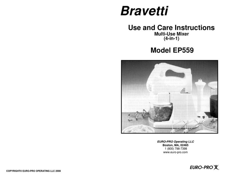
Bravetti MULTI-USE MIXER EP559 Use and care instructions
