Steridose sterimixer User manual

Magnet Lowering Device
STD0023EN00
APPLIES TO: Steridose products Sterimixer®-Low-Shear drive units with Magnet Lowering Device.
CONTENTS
1 Important safety information 1
2 About the Magnet Lowering Device 2
3 Operation 2
4 Magnet Lowering Device product range 3
5 Sensor option for automation 3
6 Maintenance 3
7 Fitting the upgrade kit to existing drive units 3
8 Fitting the optional sensor kit to the Magnet
Lowering Device 7
Copyright © 2018 Steridose
Generated by Steridocs: November 22, 2018
1. IMPORTANT SAFETY INFORMATION
1.1. Introduction
1.1.1. Purpose of this manual
Read this manual carefully before installing and using
the product. Improper use of the product can cause per-
sonal injury and damage to property, and may void the
warranty.
+NOTICE: Save this manual for future reference
1.2. Safety terminology and symbols
1.2.1. Hazard levels and indications
The following symbols are used to indicate hazard levels.
DANGER:
Indicates a hazardous situation which, if not
avoided, will result in death or serious injury.
WARNING:
Indicates a hazardous situation which, if
not avoided, could result in death or serious injury.
CAUTION:
Indicates a hazardous situation which, if
not avoided, could result in minor or moderate injury,
or, a situation that might lead to serious damage to the
product or components.
+NOTICE:
Indicates: A potential situation which, if not
avoided, could result in undesirable conditions or con-
tains tips to enhance the performance or facilitate the
installation of the product.
1.2.2. Hazard categories
Hazard categories can either fall under hazard levels or
let specific symbols replace the ordinary hazard level sym-
bols.
ELECTRICAL HAZARD:
www.steridose.com Installation & Operation | 1
INSTALLATION
& OPERATION
MANUAL

STRONG MAGNETIC FIELDS HAZARD:
CORROSIVE AGENTS HAZARD:
HAZARD FOR WEARERS OF CARDIAC PACE-
MAKER:
1.2.3. Other symbols used
In situations where confusion could arise, the icons below
are used to distinguish between the right and the wrong
procedure.
1.3. General safety
1.3.1. General statement
Undertaking any work covered by this manual may ei-
ther directly or indirectly create risks to the safety and
health of the person undertaking the work or the Sterim-
ixer/Sanimixer and/or its components while the work is
being undertaken.
It is the responsibility of the user to ensure that appro-
priate controls and precautions are identified and applied
in relation to the work covered by this document in ac-
cordance with relevant statutory, legal and industry re-
quirements to protect the health and safety of the persons
undertaking the work.
Neither this document, nor its use, in any way absolves
the user from their responsibility to ensure that the con-
trols and precautions referred to in this chapter are imple-
mented.
If, by undertaking any work covered by this document,
you become aware of any Steridose product design related
feature which could create risk to a person undertaking
work or to the Sterimixer/Sanimixer and/or its compo-
nents please contact Steridose immediately.
CAUTION:
You must observe the instructions con-
tained in this manual. Failure to do so could result
in physical injury, damage or delays.
1.4. User safety
WARNING:
This manual cannot replace specific knowl-
edge and adequately trained personnel needed for in-
stalling and handling equipment for professional use,
such as this product.
1.4.1. General safety rules
These safety rules apply:
• Always keep the work area clean
•
Pay attention to the risks presented by gas and vapors
in the work area
•
Avoid all electrical dangers. Pay attention to the risks
of electric shock or arc flash hazards
•
Always bear in mind the risk of pinching fingers,
electrical accidents and burn injuries.
1.4.2. Safety equipment
Use safety equipment according to the company and local
regulations.
1.4.3. Electrical connections
Electrical connections must be made by certified electri-
cians in compliance with all international, national, state
and local regulations. For more information about require-
ments see the relevant sections dealing specifically with
electrical connections (if applicable).
1.4.4. Hazardous liquids
The product is designed for use in liquids that can be
hazardous to your health.
WARNING:
Make sure that all personnel who work
with hazardous liquids use suitable protective equip-
ment.
1.4.5. Specific operational hazards
Specific operational hazards are listed under its respective
section.
1.4.6. Specific hazards while performing maintenance
Specific hazards while performing maintenance on the
product are listed under its respective section.
2. ABOUT THE MAGNET LOWERING DEVICE
The magnetic coupling between impeller and magnet ro-
tor is strong enough to pose a risk for damage to the bear-
ings during removing/installing the impeller. Therefore,
in conventional installations, the drive unit should be com-
pletely removed from the tank before removing/installing
the impeller, not vice-versa. The Steridose Magnet Low-
ering Device (LD) allows the user to break the magnetic
coupling without removing the drive unit from the vessel.
This is a significant ergonomic enhancement that reduces
service time and is particularly useful when working with
heavy drive units that can weight as much as 45 kg (100
lbs). Existing drive units can be retrofitted with this fea-
ture in the field, or the drive unit can be ordered with the
Magnet Lowering Device installed from the factory.
3. OPERATION
When installed on the drive unit the Magnet Lower-
ing Device can be operated as follows (see also figure
1):
2 | © Steridose www.steridose.com
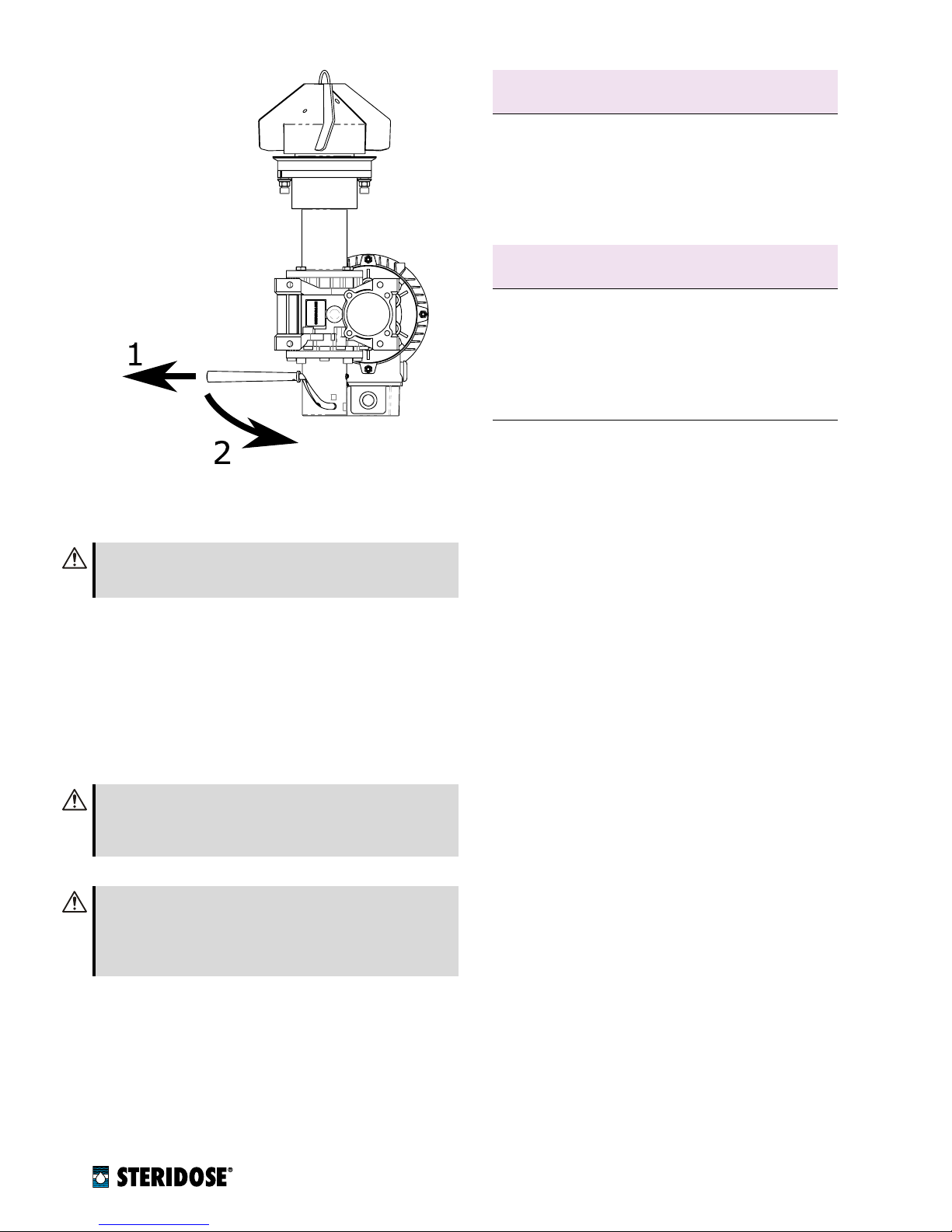
nFigure 1
Operation of the Magnet Lowering Device: 1.
pull outwards, 2. slide along slot, 3. lock into position.
WARNING:
Make sure the drive unit is not running
and in automated installations make sure that lock-out
procedures have been followed.
1.
Pull the handle outwards to unlock it from its locked
position.
2.
Slide the handle through the S-shaped slot to move
the shaft and magnet rotor down/up.
3.
Make sure that when in its final position the handle
locks back into the locked position.
CAUTION:
Make sure that while operating the Magnet
Lowering Device there is enough room for the handle
and the operator’s hand to move freely without inter-
fering with pipes, tank legs or other objects.
CAUTION:
Keep fingers away from the S-shaped slot
when operating the Magnet Lowering Device, the mag-
netic forces present and the spring-loaded locking han-
dle might cause involuntary movements with risk for
pinching fingers.
See figure 2 for an example of a warning sign that can
be used to avoid incorrect installation/removal of the
impeller.
4. MAGNET LOWERING DEVICE PRODUCT
RANGE
The Magnet Lowering Device is available for non-ATEX
Sterimixer from size 85 and up. In order to accommodate
Mixer size
Delivered before 2018
Magnet Lowering Device
DU LD UPGRADE KIT a
85 113062
120/150 112393
120/190 112830
120H 112832
210 112834
Mixer size
Delivered in/after 2018
Magnet Lowering Device
DU LD KIT b
85 113121
120/150 112835
120/190 112836
120H 112837
210 112838
a
includes extended drive unit flange, extended shaft and lowering device
bincludes lowering device, assumes re-using shaft and flange
nTable 1
Part numbers for upgrade kits. Refer to sec-
tion 7 for details.
for the magnet rotor when in the lowered position, the use
of the Magnet Lowering Device requires the drive unit to
be equipped with the cooling jacket extension.
Retrofit kits are available that facilitate upgrading ex-
isting installations with this feature. Two different kits are
available depending on the original drive unit’s age, see
table 1. Fitting the upgrade kit is described in section 7.
5. SENSOR OPTION FOR AUTOMATION
The lowering device can be equipped with an optional
sensor that verifies that the Magnet Lowering Device is in
the raised position and that the mixer can be started. This
sensor included a LED which facilitates quick visual feed-
back (rotor up/down) during walk-around inspections of
the plant.
6. MAINTENANCE
The Magnet Lowering Device does not require special
maintenance.
7. FITTING THE UPGRADE KIT TO EXISTING
DRIVE UNITS
The upgrade kits (see table 1 for part numbers) come in
two versions:
DU LD UPGRADE KIT:
This kit must be used when up-
grading drive units that were delivered before 2018
(and after 2008, consult the factory for details). This
kit can also be used to upgrade drive units that do
not have the cooling jacket extension (adding the low-
ering device will change the space requirement of
the drive unit!). The kit includes extended drive unit
flange, an extended shaft, the mounting tool and the
lowering device (items 1, 2, 3, 4 in figure 3).
www.steridose.com Installation & Operation | 3

nFigure 2 Example of a sign for the correct use of the Magnet Lowering Device.
4 | © Steridose www.steridose.com
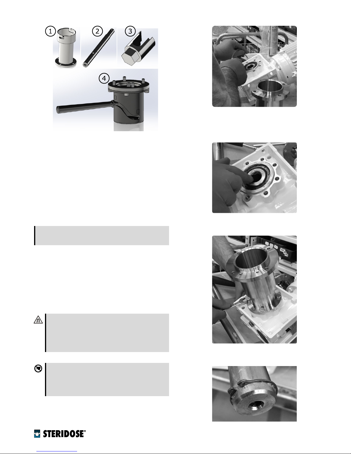
nFigure 3
Upgrade kit contents: 1. extended drive unit
flange, 2. extended shaft, 3 mounting tool, 4. the lowering
device.
DU LD KIT:
This kit is intended to be used when up-
grading drive units delivered in or after 2018. Since
the standard drive unit with cooling extension deliv-
ered in or after 2018 are already equipped with the
modified drive unit flange and shafts with bottom
thread (please consult factory), this kit only contains
the mounting tool and the lowering device (items 3
and 4 in figure 3).
+NOTICE:
Due to international shipping regulations
grease required for successful retrofit of the lowering
device is NOT included in the kits.
7.1. Steps for assembling the Magnet Lowering Device.
1. Clean the drive unit and especially the gearbox thor-
oughly.
2.
Remove the drive unit flange from the gearbox by
loosening the screws that fix it to the gearbox.
3. Remove the shaft from the gearbox’s hollow-shaft.
4.
Remove the magnet rotor from the shaft.
STRONG MAGNETIC FIELDS HAZARD:
The
Sterimixer impeller and magnetic rotor include
strong magnets with the associated risk of pinching
fingers and permanently damaging magnetic cards
(e.g. credit cards) if being close to these compo-
nents.
HAZARD FOR WEARERS OF CARDIAC PACE-
MAKER:
The Sterimixer impeller and magnetic
rotor include strong magnets thus personnel
equipped with pacemaker shall not handle these
components.
5.
Check the gearbox mounting frame for damage and
remove any paint, leaving the surface of interface
between flange and gearbox clean, even and smooth.
6.
Apply a suitable grease (e.g. Chesterton 630 SXCF)
to the gearbox’s hollow-shaft and the frame interface.
This will facilitate movement of the shaft and protect
against corrosion.
7.
Fit the extended drive unit flange to the gearbox and
tighten the screws.
8.
Fit the bottom circlip on the shaft (use protective eye-
wear when fitting circlips).
www.steridose.com Installation & Operation | 5

9.
Fit the keys in the keyways on the extended shaft and
apply grease (e.g. Chesterton 630 SXCF).
10.
Put the drive unit on a flat surface. Verify that the
gearbox’s hollow shaft is completely free of deforma-
tions or burrs. A common file can be used for this
purpose.
11.
Verify that the shaft can move smoothly up and down
the gearbox, all the way to the stop provided by the
bottom circlip. If necessary use a file to de-burr and
straighten the hollow-shaft keyway and/or the bot-
tom shaft key.
12.
Once the shaft runs smoothly up and down the gear-
box, apply additional grease to the gearbox’s hollow
shaft.
13.
Apply a suitable thread-sealant/locking liquid (e.g.
Loctite 243, Loctite 2400) to the Magnet Lowering
Device screw.
14.
Screw the Magnet Lowering Device mounting screw
into the bottom end of the shaft and tighten to 17 Nm
(150 in-lb) with assistance of the mounting tool.
6 | © Steridose www.steridose.com
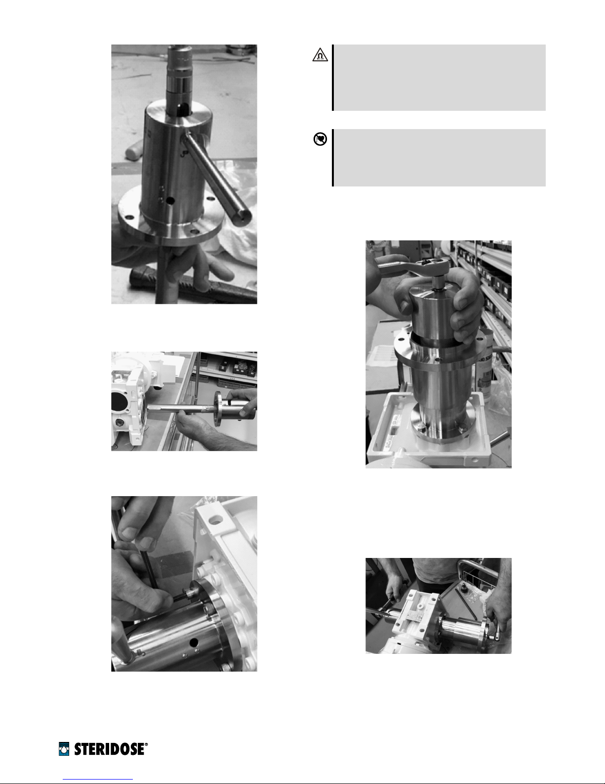
15.
Insert the shaft and Magnet Lowering Device in the
gearbox hollow-shaft.
16.
Screw the Magnet Lowering Device into the gearbox
frame.
17.
Put the drive unit upright (use care and appropriate
lifting devices where required) and raise the shaft by
operating the Magnet Lowering Device.
STRONG MAGNETIC FIELDS HAZARD:
The
Sterimixer impeller and magnetic rotor include
strong magnets with the associated risk of pinching
fingers and permanently damaging magnetic cards
(e.g. credit cards) if being close to these compo-
nents.
HAZARD FOR WEARERS OF CARDIAC PACE-
MAKER:
The Sterimixer impeller and magnetic
rotor include strong magnets thus personnel
equipped with pacemaker shall not handle these
components.
Fix the magnet rotor on the shaft with the magnet
rotor screw.
18.
For final tightening of the magnet rotor and Magnet
Lowering Device mounting screw, put the drive unit
on its side (use care and appropriate lifting devices
where required) and tighten as shown in the picture
below.
8. FITTING THE OPTIONAL SENSOR KIT TO
THE MAGNET LOWERING DEVICE
1.
Remove the M3x3 screws from the Magnet Lowering
Device housing.
www.steridose.com Installation & Operation | 7

2.
Re-use the M3x3 screws to fix the sensor bracket to
the housing.
3.
Mount the sensor on the sensor bracket using the 2
provided M3x14 screws and nuts.
4.
Verify that the sensor works as intended. Since the
magnetic sensing range might pick up interference
from other moving parts in the Magnet Lowering
Device the sensor bracket has a slotted hole to allow
for adjustment of the sensor position to eliminate
interference.
Sensor technical data can be obtained from the sensor
supplier’s product information.
8 | © Steridose www.steridose.com

www.steridose.com Installation & Operation | 9

About us
Steridose is a global company and our world head-
quarters are located in Tumba, Sweden. We are highly
specialized in the design, development and manufactur-
ing of magnetic coupled mixers and radial diaphragm
valves.
Steridose is part of the Velcora group, with regional
offices in key locations around the world.
Steridose is represented in important certifying and
standards organizations, most notably and relevant to
the pharmaceutical industry, ASME BioProcessing Equip-
ment standards committee (BPE). We help develop the
standards and Good Manufacturing Practices that mini-
mize risk for process interference.
Steridose partners with the best distributors and repre-
sentatives in the industry all over the world. Together we
become the perfect mix; a premium product with global
references combined with local presence for product and
application support.
Steridose AB
Himmelsbodavägen 7
SE 147 39 Tumba, Sweden
Phone: +46 8 449 9900
www.steridose.com
Steridose Inc.
5020 World Dairy Drive
Madison, WI 53718, U.S.A.
Phone: +1 608 229 5225
www.steridose.com
Visit our website for the latest version of this document. The original instruction is in English, all non-English
instructions are translations of the original instruction. © Steridose AB
STD0023EN00 Revision en-1.0.0 - 20180831
Other manuals for sterimixer
1
Table of contents


