Steris Basil 3600 User manual

UNCRATING/INSTALLATION INSTRUCTIONS
Basil®3600 Bedding Dispenser
(2009-03-31) P122997-217

i
Introduction Uncrating/Installation Instructions 122997-217
Follow each step of the UNCRATING/INSTALLATION INSTRUCTIONS in the
order presented. Open the carton carefully to avoid damage to the
equipment inside. If you find any indication of damage to the equip-
ment, no matter how slight, show it to your supervisor.
To properly install this Basil®3600 Bedding Dispenser, you need the
equipment drawing (previously furnished) showing all utility service
and space requirements. If the equipment drawing cannot be
located, contact STERIS for a replacement copy, providing the serial
and model numbers of the bedding dispenser.
Once installed, equipment operation should be tested by a qualified
service technician prior to use.
If STERIS supervision is desired for installing and starting up this
equipment, contact STERIS for pricing and availability of this service
in your region.
Advisory IMPORTANT: A listing of the Safety Precautions to be observed
when uncrating/installing and testing this bedding dispenser can be
found in SECTION 1 of this manual. Do not begin uncrating/installing
the equipment until you have become familiar with this information.
Any alteration of this equipment not authorized or performed by
STERIS will void the warranty. Alteration of equipment which could
adversely affect its operation and efficacy and may violate national,
state and local laws or regulations.
IMPORTANT: Refer to local occupational health and safety regula-
tions, as well as electric and plumbing codes, for any special require-
ments that may pertain to installation of this bedding dispenser.
Indications For Use The Basil 3600 Bedding Dispenser is an automatic, conveyorized
unit designed to dispense bedding into animal cages as they pass
through the unit. The bedding dispenser is capable of handling most
solid bedding used in the care of laboratory animals.
A WORD FROM STERIS CORPORATION
©2009, STERIS Corporation. All rights reserved. Printed in Canada.

ii
122997-217 Uncrating/Installation Instructions Introduction
Service Information A thorough preventive maintenance program is essential to help
ensure safe and proper equipment operation. Customers are
encouraged to contact STERIS concerning our comprehensive
annual maintenance program. Under the terms of the program, pre-
ventive maintenance, adjustments and replacement of worn parts
are performed on a scheduled basis to help ensure equipment per-
formance at peak capability and to help avoid untimely or costly
interruptions.
STERIS maintains a global staff of well-equipped, qualified service
technicians to provide this service, as well as expert repair services.
Please contact STERIS for details.
STERIS carries a complete line of accessories for use in this equip-
ment. A STERIS representative will gladly review these with you.
Manufactured by:
Corporation STERIS Canada
490, boulevard Armand-Paris
Québec, Qc,
G1C 8A3
CANADA
The base language of this document is
ENGLISH. Any translation must be made
from the base language document.
STERIS Limited
STERIS House
Jays Close
Viables
Basingstoke
Hampshire
RG22 4AX
United Kingdom
Sales and Service:
STERIS Corporation
5960 Heisley Road
Mentor, Ohio 44060
440-354-2600 • 800-444-9009
www.steris.com

iii
Table of Contents Uncrating/Installation Instructions 122997-217
A WORD FROM STERIS CORPORATION ................................................................ I
Advisory ........................................................................................................................................................... i
Indications For Use .......................................................................................................................................... i
Service Information ..........................................................................................................................................ii
1 SAFETY PRECAUTIONS .....................................................................................1-1
2 UNCRATING INSTRUCTIONS .............................................................................2-1
2.1 Open Crates .......................................................................................................................................... 2-1
2.2 Move Sections and Remove Skids ........................................................................................................ 2-2
2.3 Prepare Bedding Dispenser For Installation ......................................................................................... 2-3
3 INSTALLATION INSTRUCTIONS ........................................................................3-1
3.1 Before Installing Bedding Dispenser ..................................................................................................... 3-1
3.2 Technical Specifications ........................................................................................................................ 3-2
3.2.1 Voltage, Amperage and Power Consumption ................................................................................ 3-2
3.2.2 Permissible Environmental Conditions ........................................................................................... 3-2
3.2.3 Seismic Anchorage System ........................................................................................................... 3-2
3.3 Installing Conveyor ................................................................................................................................ 3-3
3.4 Installing Dust Collection System .......................................................................................................... 3-4
3.5 Connect Utilities ..................................................................................................................................... 3-5
3.6 Cleanup ................................................................................................................................................. 3-6
4 INSTALLATION CHECKLIST ...............................................................................4-1
5 OPERATIONAL TEST ..........................................................................................5-1
5.1 Start-Up Test Procedures ...................................................................................................................... 5-1
5.2 Transfer Plates For Different Bedding Types ........................................................................................ 5-3
5.2.1 Curved Transfer Plate With Bedding Fall Guide ............................................................................5-4
5.2.2 Flat Transfer Plate ........................................................................................................................... 5-6
TABLE OF CONTENTS
Section
Number Description Page

v
List of Illustrations Uncrating/Installation Instructions 122997-217
Section 2: Uncrating Instructions
2-1 Crates .............................................................................................................................................. 2-2
Section 3: Installation Instructions
3-1 Disconnect Switch For Electrical Supply ........................................................................................ 3-1
3-2 Installing Conveyor .......................................................................................................................... 3-3
3-3 Dust Collection System ................................................................................................................... 3-4
3-4 Conveyor Motor Wiring .................................................................................................................... 3-5
Section 5: Operational Test
5-1 Adjust Cage Size For Flip-Over Rotation ........................................................................................ 5-2
5-2 Bedding Types and Transfer Plates ................................................................................................ 5-3
5-3 Installing Curved Transfer Plate and Bedding Fall Guide ............................................................... 5-5
5-4 Installing Flat Transfer Plate ............................................................................................................ 5-6
LIST OF ILLUSTRATIONS
Figure Description Page

1-1
Safety Precautions Uncrating/Installation Instructions 122997-217
1
The following Safety Precautions must be observed when uncrating/installing, operating or servicing this Basil®
3600 Bedding Dispenser. WARNING indicates the potential for personal injury and CAUTION indicates the
potential for damage to equipment. For emphasis, certain Safety Precautions are repeated throughout the manual.
It is important to review ALL Safety Precautions before operating or servicing the bedding dispenser.
WARNING – PERSONAL INJURY AND/OR EQUIPMENT DAMAGE HAZARD:
WARNING – ELECTRIC SHOCK AND/OR BURN HAZARD:
WARNING – LACERATION AND/OR EYE INJURY HAZARD:
WARNING – LACERATION HAZARD:
WARNING – HEALTH HAZARD:
Fans and motors have rotating parts and pinch points. When operating a unit equipped with dust collec-
tion system, ensure exhaust guard, elbow and dust bag are securely in place.
Repairs and adjustments to this equipment must be made only by STERIS or STERIS-trained service
personnel. Non-routine maintenance performed by unqualified personnel or installation of unauthorized
parts could cause personal injury, result in improper equipment performance, void the warranty or result
in costly damage. Contact STERIS regarding service options.
When moving the unit, use a forklift.
Disconnect all utilities to dispenser before servicing. Do not service dispenser unless all utilities have
been properly locked out. Always follow local lockout-tagout and electrical safety-related work practice
standards.
Fasteners and star washers are used to ensure protective bonding continuity. Always reinstall any star
washer which may have been removed during installation or servicing.
When removing bands, wear appropriate Personal Protective Equipment (PPE) and always use a tool
specifically designed to cut bands. Bands used to secure this carton can cause personal injury when
cut and tension is released.
When removing bolts, wear gloves to protect your hands.
Vapors from solvents can be harmful. Use with adequate ventilation. Follow directions on the container.
SAFETY PRECAUTIONS

1-2
122997-217 Uncrating/Installation Instructions Safety Precautions
CAUTION – POSSIBLE EQUIPMENT DAMAGE:
IMPORTANT: Refer to the local occupational health and safety regulations, as well as electric and plumbing
codes, for any special requirements that may pertain to installation of this unit.
After utilities are connected to equipment, slowly remove the protective adhesive paper from the exte-
rior cabinet panels to reduce the level of static discharge.
Ensure a cooling fan is attached to rear motor shaft. Verify fan blades are positioned to send airflow to
motor. Motor will overheat without a cooling fan.
Once electrical power is connected, verify each motor for correct rotation. Incorrect motor rotation may
result in equipment damage and improper equipment operation.
When removing adhesives from stainless steel, use a solvent specially formulated for that purpose. Rub
in a back-and-forth motion (in same direction as surface grain). Solvent rubbed in a circular motion or
applied with a wire brush or steel wool on bedding dispenser assemblies can be harmful to stainless
steel. Do not use solvents on painted surfaces.
1-3
Safety Precautions Uncrating/Installation Instructions 122997-217
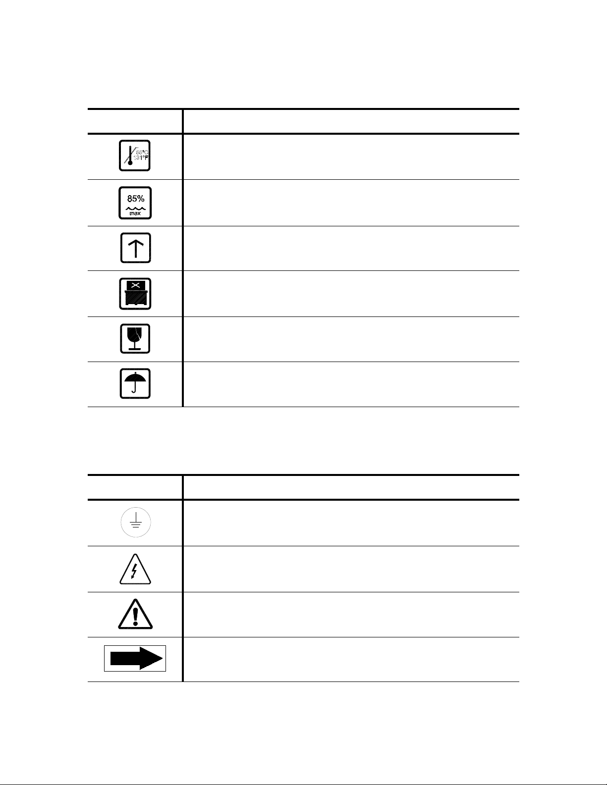
The table below contains symbols which may be on the crate of your Basil 3600 Bedding Dispenser:
The table below contains symbols which may be on your Basil 3600 Bedding Dispenser components:
Table 1-1. Definition of Symbols
Symbol Definition
Maximum Shipping and Storing Temperature.
Maximum Humidity Level.
This Way Up.
Do Not Stack.
Fragile.
Keep Dry.
Table 1-2. Definition of Symbols
Symbol Definition
Protective Earth (Ground).
Warning! Risk of Electrical Shock.
Warning. Refer to Manual For Further Information.
Rotation Direction.

1-4
122997-217 Uncrating/Installation Instructions Safety Precautions
The table below contains symbols which may be on the identification nameplate of your Basil 3600 Bedding
Dispenser:
Table 1-3. Definition of Symbols
Symbol Definition
MOD. Model Number of Bedding Dispenser.
SER. Serial Number of Bedding Dispenser.
kW Power Rating of Bedding Dispenser.
VVoltage Rating of Bedding Dispenser.
AAmperage Rating of Bedding Dispenser.
PH/Hz Phase of Bedding Dispenser/Hertz – Frequency of Bedding Dispenser.
WIRE X + PE Number of Wires [X] in the Electrical Cable and Protective Ground Wire.
2
2-1
Uncrating Instructions Uncrating/Installation Instructions 122997-217
2.1 Open Crates NOTE: Before opening any crates, note the following:
1) Unit weighs approximately 1,800 lb (816 kg). Use a forklift to move
the unit.
2) Uncrate on level floor as close to installation site as possible.
3) Verify each crate for identification sticker indicating crate number
(see Figure 2-1).
1. Ensure crates are positoned so they open from top. Provide a
clear work area on all sides.
•Crate 1 contains conveyor base and pans for dust collection
system.
•Crate 2 contains load/unload conveyor.
2. Carefully cut and remove bands from Crate 1. Discard bands
before continuing.
3. Using a nail puller, remove and discard top wooden panel.
4. Using a nail puller, remove and discard side wooden panels.
5. Using a nail puller, remove and discard wooden frame from con-
veyors.
6. Remove and discard polystyrene wrap from around unit.
7. Take out two «V» shaped pans from crate and put safely aside.
8. Repeat Steps 1 to 7 for Crate 2.
IMPORTANT: A listing of the Safety Precautions to be observed when uncrating/installing and testing this
bedding dispenser can be found in SECTION 1 of this manual. Do not begin uncrating/installing the
equipment until you have become familiar with this information.
WARNING – PERSONAL INJURY
AND/OR EQUIPMENT DAMAGE
HAZARD: When moving the
unit, use a forklift.
WARNING – LACERATION AND/
OR EYE INJURY HAZARD:
When removing bands, wear
appropriate Personal Protec-
tive Equipment (PPE) and
always use a tool specifically
designed to cut bands. Bands
used to secure this carton can
cause personal injury when cut
and tension is released.
UNCRATING INSTRUCTIONS

2-2
122997-217 Uncrating/Installation Instructions Uncrating Instructions
2.2 Move Sections and
Remove Skids
1. With units still mounted on skids, use a forklift to move both sec-
tions to installation site.
2. Remove six lag bolts securing each section base to skid.
3. Remove and discard skid from under each section. If necessary,
use a piece of plywood as a small ramp to slide each section
from skid to floor.
Figure 2-1. Crates
WARNING – PERSONAL INJURY
AND/OR EQUIPMENT DAMAGE
HAZARD: When moving the
unit, use a forklift.
WARNING – LACERATION HAZ-
ARD: When removing bolts,
wear gloves to protect your
hands.

2-3
Uncrating Instructions Uncrating/Installation Instructions 122997-217
2.3 Prepare Bedding
Dispenser For
Installation
NOTE: Do not remove protective adhesive paper from the exterior
cabinet panels until after utilities are connected.
1. Remove all tape from bedding dispenser.
2. Locate electrical box compartment keys located in an envelope
taped on bedding dispenser electrical box.
3. Remove envelope labeled «Customer Information» containing
Operator Manual (P122996-163) taped on bedding dispenser
electrical box. Ensure appropriate person receives Operator
Manual. Give keys to department supervisor.
IMPORTANT: Items needed to assemble bedding dispenser are
enclosed in a box labeled "Hardware" included inside Crate 1
(see number on sticker affixed on crate). "Hardware" box
contains spare bolts, washers, nuts and other items.
4. Discard all packing material removed during uncrating proce-
dures.
CAUTION – POSSIBLE EQUIP-
MENT HAZARD:
• After utilities are connected
to equipment, slowly remove
the protective adhesive
paper from the exterior cabi-
net panels to reduce the
level of static discharge.
• When removing adhesives
from stainless steel, use a
solvent specially formulated
for that purpose. Rub in a
back-and-forth motion (in
same direction as surface
grain). Solvent rubbed in a
circular motion or applied
with a wire brush or steel
wool on bedding dispenser
assemblies can be harmful
to stainless steel. Do not use
solvents on painted sur-
faces.
3
3-1
Installation Instructions Uncrating/Installation Instructions 122997-217
3.1 Before Installing
Bedding Dispenser
See Figure 3-1.
1. Review installation requirements:
a. Clearance – clearance space shown on equipment drawing
(122-998-267 or 122-998-283) indicates space necessary
for easy installation and proper operation and maintenance
of Basil®3600 Bedding Dispenser.
For best results, tunnel cage washer conveyor should be 10-
3/4 to 11" (273 to 279 mm) higher than bedding dispenser
conveyor.
Tunnel cage washer conveyor opening must be aligned
within 1/8" to ensure functionality of chute conveyor safety
device.
Bedding dispenser and tunnel washer can be welded
together; however, placing them next to each other without a
gap is sufficient.
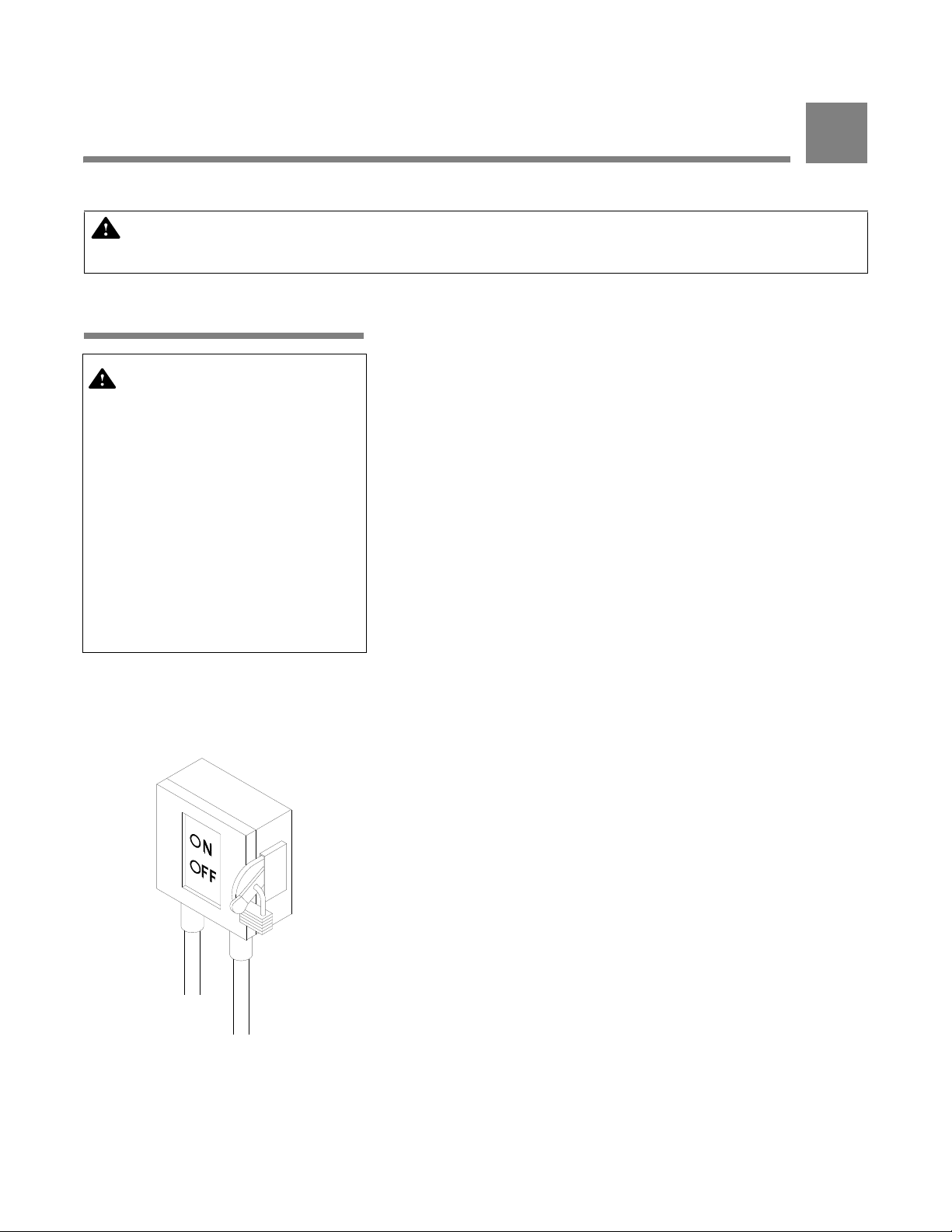
b. Utility service lines:
• Disconnect switch (not provided by STERIS) must be
installed in electric supply line near bedding dispenser
(see Figure 3-1). Disconnect switch must be capable of
being locked in OFF position only.
• If bedding dispenser is installed next to other equipment,
disconnect switch should be located so service can be
shut off to one piece of equipment at a time.
• Utility service requirements are as shown on equipment
drawing. Verify equipment drawing or identification plate
(located over electrical box cover) for proper voltage.
2. Ensure bedding dispenser is placed, as shown on equipment
drawing (122-998-267 or 122-998-283), in correct relation to
building supply lines.
NOTE: If bedding dispenser is not at installation site, see
SECTION 2.2, MOVE SECTIONS AND REMOVE SKIDS, for proper
moving instructions.
3. Verify bedding dispenser is level.
a. Place a spirit level on top of each conveyor.
b. If necessary, level bedding dispenser, end-to-end and side-
to-side, by adjusting leveling legs.
IMPORTANT: A listing of the Safety Precautions to be observed when uncrating/installing and testing this
bedding dispenser can be found in SECTION 1 of this manual. Do not begin uncrating/installing the
equipment until you have become familiar with this information.
WARNING – PERSONAL INJURY
AND/OR EQUIPMENT DAMAGE
HAZARD: Repairs and adjust-
ments to this equipment must be
made only by STERIS or STERIS-
trained service personnel. Non-
routine maintenance performed
by unqualified personnel or
installation of unauthorized parts
could cause personal injury,
result in improper equipment
performance, void the warranty
or result in costly damage. Con-
tact STERIS regarding service
options.
Figure 3-1. Disconnect Switch For
Electrical Supply
INSTALLATION INSTRUCTIONS

3-2
122997-217 Uncrating/Installation Instructions Installation Instructions
3.2 Technical
Specifications
These specifications are intended to describe the technical informa-
tion given on the identification nameplate of your bedding dispenser
and to state other relevant information. Verify equipment drawing or
identification nameplate, located in chemical storage compartment,
for proper voltage and amperage.
3.2.1 Voltage, Amperage and
Power Consumption
The Basil 3600 Bedding Dispenser operates on:
• 208 V, 60 Hz, three-phase, neutral, four-wire
• 480 V, 60 Hz, three-phase, three-wire
Maximum current and power consumptions are:
Amp kW
• 208 V 13.9 2.6
• 480 V 5.6 2.7
See SECTION 3.5, CONNECT UTILITIES, for proper connection.
3.2.2 Permissible
Environmental Conditions
This equipment is designed to give optimal results in an environment
where maximum relative humidity is 80% for temperatures up to 88°F
(31°C), decreasing linearly to 50% relative humidity at 104°F (40°C).
3.2.3 Seismic Anchorage
System
A seismic anchorage system is available for high-risk seismic zones.
3-3
Installation Instructions Uncrating/Installation Instructions 122997-217
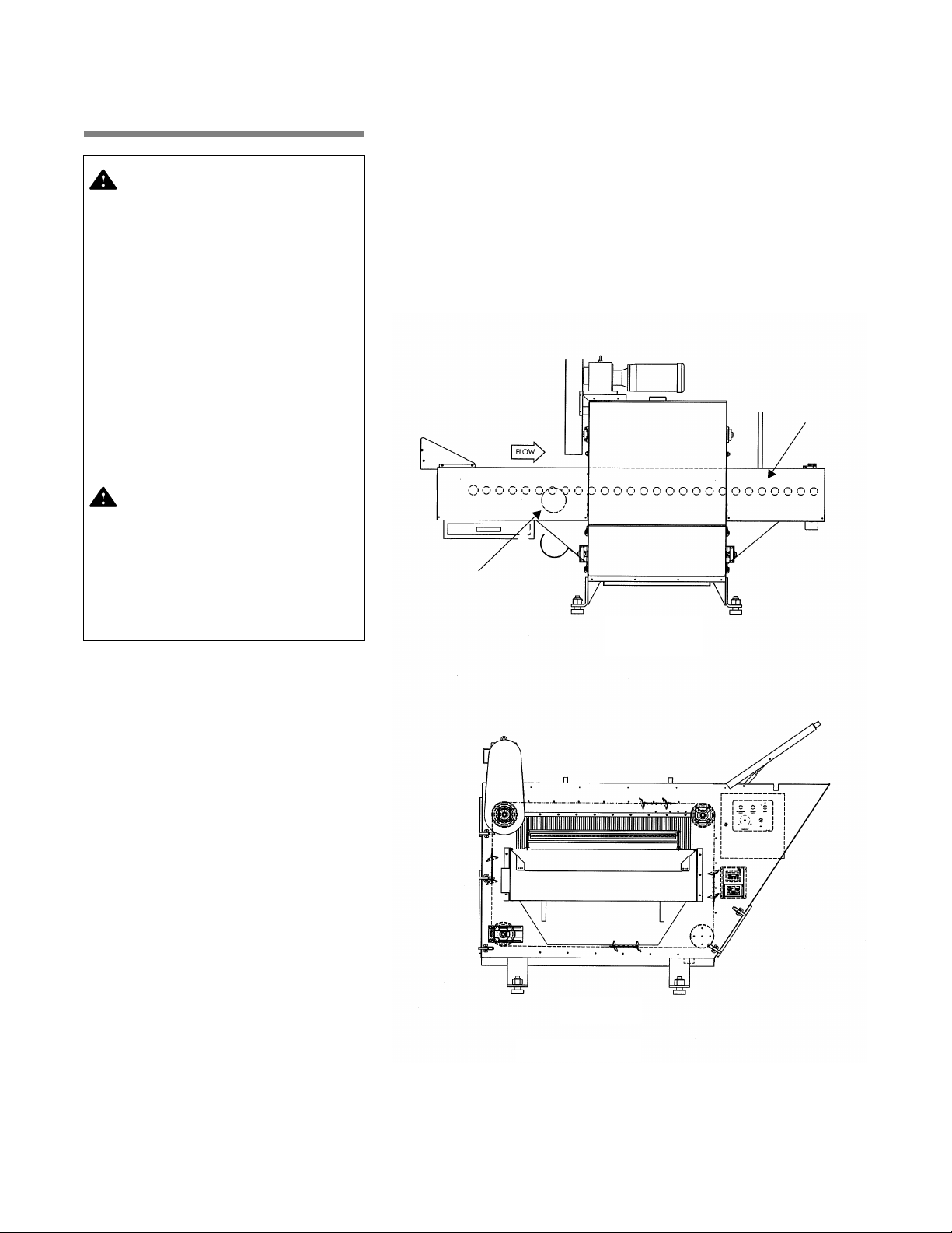
3.3 Installing Conveyor See Figure 3-2.
1. Insert load/unload conveyor into bedding dispenser using four
provided lag bolts.
2. Install base conveyor inlet and base conveyor outlet using 1/4-
20 x 3/4" bolts.
3. Install dust deflectors.
WARNING – PERSONAL INJURY
AND/OR EQUIPMENT DAMAGE
HAZARD: Repairs and adjust-
ments to this equipment must
be made only by STERIS or
STERIS-trained service person-
nel. Non-routine maintenance
performed by unqualified per-
sonnel or installation of unau-
thorized parts could cause
personal injury, result in
improper equipment perfor-
mance, void the warranty or
result in costly damage. Contact
STERIS regarding service
options.
WARNING – ELECTRIC SHOCK
AND/OR BURN HAZARD: Fas-
teners and star washers are
used to ensure protective bond-
ing continuity. Always reinstall
any star washer which may have
been removed during installa-
tion or servicing.
SIDE VIEW
Ventilation System
FRONT VIEW
(Load Side)
Load/Unload
Conveyor
Figure 3-2. Installing Conveyor

3-4
122997-217 Uncrating/Installation Instructions Installation Instructions
3.4 Installing Dust
Collection System
See Figure 3-3.
1. Connect 6" (152 mm) diameter black hose and reducer to inlet
elbow using two provided clamps.
2. Connect other end of hose to exhaust filter using provided
clamp.
3. Ensure black hose does not hang or form humps below suction
system inlet level to avoid a loss of suction or hose being
clogged.
4. Unscrew metal setscrews located over dust collection system
exhaust.
5. Connect 6" (152 mm) galvanized steel elbow over dust collection
system blower discharge guard.
6. Insert sleeve inside dust collection bag.
7. Large lip must be inserted so it holds bag tightly.
8. Secure sleeve to bag with provided clamp.
9. Slide sleeve over elbow and secure with provided clamps.
10. Secure elbow over dust collection system exhaust with previ-
ously removed setscrews.
WARNING – PERSONAL INJURY
AND/OR EQUIPMENT DAMAGE
HAZARD: Repairs and adjust-
ments to this equipment must be
made only by STERIS or STERIS-
trained service personnel. Non-
routine maintenance performed
by unqualified personnel or
installation of unauthorized parts
could cause personal injury,
result in improper equipment
performance, void the warranty
or result in costly damage. Con-
tact STERIS regarding service
options.
WARNING – ELECTRIC SHOCK
AND/OR BURN HAZARD: Fas-
teners and star washers are used
to ensure protective bonding
continuity. Always reinstall any
star washer which may have
been removed during installa-
tion or servicing.
Figure 3-3. Dust Collection System
Dust Collection
System Blower
Reducer
Setscrews
6" Galvanized
Steel Elbow
Sleeve
Hose
Dust Collection
Bag
Bag
Clamp
IMPORTANT: Avoid hose hangs
below dust collector inlet.

3-5
Installation Instructions Uncrating/Installation Instructions 122997-217
3.5 Connect Utilities See Figure 3-4.
1. Connect conveyor motor as per Figure 3-4.
2. Connect dust collection system electrical supply line from unit to
dust collection motor, securing connections with wire nuts:
• Red wire with T1
• Black wire with T2
• Blue wire with T3
3. If bedding dispenser is to be used with a Basil®6700 Tunnel
Cage Washer, make following wire connections:
a. Secure wire conduit located at unload end of Basil 6700
Tunnel Cage Washer in bedding dispenser electrical box.
b. Connect wires to their corresponding (numbered) terminal in
bedding dispenser electrical box.
4. Knocked-down shipment and photoelectric conveyor stop:
a. Secure wire conduit of photoelectric sensor in bedding
dispenser electrical box.
b. Connect wires to their corresponding (numbered) terminals
in bedding dispenser electrical box.
WARNING – PERSONAL INJURY
AND/OR EQUIPMENT DAMAGE
HAZARD: Repairs and adjust-
ments to this equipment must be
made only by STERIS or
STERIS-trained service person-
nel. Non-routine maintenance
performed by unqualified per-
sonnel or installation of unau-
thorized parts could cause
personal injury, result in
improper equipment perfor-
mance, void the warranty or
result in costly damage. Contact
STERIS regarding service
options.
WARNING – ELECTRIC SHOCK
AND/OR BURN HAZARD: Fas-
teners and star washers are
used to ensure protective bond-
ing continuity. Always reinstall
any star washer which may have
been removed during installa-
tion or servicing.
Figure 3-4. Conveyor Motor Wiring

3-6
122997-217 Uncrating/Installation Instructions Installation Instructions
3.6 Cleanup 1. Remove any adhesive found on panels with a small amount of
nonflammable cleaning solvent. Keep solvents away from all
painted surfaces or damage may result.
2. Remove all protective paper from unit cabinet panels. Slowly
peel paper away from stainless steel to reduce level of static dis-
charge.
3. Inspect dispenser and work area to ensure all materials used
during installation have been removed.
THIS COMPLETES THE INSTALLATION. Before operating bedding
dispenser, confirm all items on installation checklist (SECTION 4) have
been satisfactorily implemented and operational test (SECTION 5) is
conducted by a qualified service technician.
WARNING – HEALTH HAZARD:
Vapors from solvents can be
harmful. Use with adequate
ventilation. Follow directions
on the container.
CAUTION – POSSIBLE EQUIP-
MENT HAZARD:
• After utilities are connected
to equipment, slowly remove
the protective adhesive
paper from the exterior cabi-
net panels to reduce the
level of static discharge.
• When removing adhesives
from stainless steel, use a
solvent specially formulated
for that purpose. Rub in a
back-and-forth motion (in
same direction as surface
grain). Solvent rubbed in a
circular motion or applied
with a wire brush or steel
wool on bedding dispenser
assemblies can be harmful
to stainless steel. Do not use
solvents on painted sur-
faces.

4
4-1
Installation Checklist Uncrating/Installation Instructions 122997-217
Installation checklist must be completed after Basil®3600 Bedding
Dispenser is installed and prior to performing operational test to help
ensure complete and correct installation.
NOTE: Contact STERIS to schedule a technician to test your installa-
tion and demonstrate proper equipment operation.
❑Disconnect switch (not provided by STERIS), capable of being
locked in OFF position only, is installed in electrical supply line in
same room as bedding dispenser and within 10 feet (3 m) of
electrical control box and in compliance with local occupational
health and safety regulations, as well as electric codes for any
special requirements that may pertain to installation of this bed-
ding dispenser.
NOTE: If bedding dispenser is installed next to other equipment,
disconnect switches should be located so service can be shut off
to one piece of equipment at a time.
❑Bedding dispenser is positioned as shown on equipment drawing
(122-998-267 or 122-998-283), with required clearance space
and in relation to building supply lines.
❑Electrical supply for bedding dispenser is as specified on equip-
ment drawing.
❑Both conveyor motors (load/unload drive motor and bedding
conveyor motor) rotate in same direction shown by arrow.
❑Exhaust guard, elbow and dust collection bag are in position.
❑Verify cage flip-over system is firmly installed and in proper posi-
tion.
❑Verify photoelectric switch is properly installed at end of unload
conveyor.
IMPORTANT: A listing of the Safety Precautions to be observed when uncrating/installing and testing this
bedding dispenser can be found in SECTION 1 of this manual. Do not begin uncrating/installing the
equipment until you have become familiar with this information.
INSTALLATION CHECKLIST
5
5-1
Operational Test Uncrating/Installation Instructions 122997-217
5.1 Start-Up Test
Procedures
See Figure 5-1.
1. Ensure storage hopper is filled with bedding.
2. Position Power ON/OFF selector switch to ON.
3. Pull Unit STOP pushbutton (red) to start conveyor.
4. After pulling Unit STOP pushbutton, wait two seconds and push
Dispenser ON/OFF pushbutton to activate bedding dispenser
system.
5. Press Dust Collector ON/OFF pushbutton to activate dust col-
lection system.
6. If necessary, adjust amount of bedding desired in cages using
Dispenser Adjustment knob to increase/decrease bedding flow.
7. Position a few cages top side up on load-end conveyor.
NOTE: Cages of cage flip-over system are automatically flipped
from inverted position to top side up position when exiting Basil®
6700 Tunnel Cage Washer.
8. Let bedding dispenser run for a few minutes.
9. Verify rotation of conveyor motors. Motors should turn in direc-
tion shown by arrow. If motors are rotating in wrong direction,
disconnect main power, reverse any two three-phase wires and
verify shaft rotation again.
10. Verify rotation of dust collection motor fan. Fan should rotate
clockwise (in same direction as outlet of blower casing). If fan
motor is rotating in wrong direction, disconnect main power,
reverse any two three-phase wires and verify shaft rotation
again.
11. Adjust cage size for cage flip-over system as follows:
a. Remove two 10-32 screws.
b. Move adjustment rod to one of the four positions available
(see Figure 5-1).
IMPORTANT: Adjustment rod must be installed in the same
position on each side of cage flip-over module.
12. Position Power ON/OFF selector switch to OFF position. Verify
bedding dispenser conveyor operation stops.
IMPORTANT: A listing of the Safety Precautions to be observed when uncrating/installing and testing this
bedding dispenser can be found in SECTION 1 of this manual. Do not begin uncrating/installing the
equipment until you have become familiar with this information.
WARNING – PERSONAL INJURY
AND/OR EQUIPMENT DAMAGE
HAZARD: Fans and motors
have rotating parts and pinch
points. When operating a unit
equipped with dust collection
system, ensure exhaust guard,
elbow and dust bag are
securely in place.
WARNING – ELECTRIC SHOCK
AND/OR BURN HAZARD: Dis-
connect all utilities to dis-
penser before servicing. Do not
service dispenser unless all
utilities have been properly
locked out. Always follow local
lockout-tagout and electrical
safety-related work practice
standards.
CAUTION – POSSIBLE EQUIP-
MENT HAZARD: Once electri-
cal power is connected, verify
each motor for correct rota-
tion. Incorrect motor rotation
may result in equipment dam-
age and improper equipment
operation.
OPERATIONAL TEST
Table of contents
Popular Dispenser manuals by other brands


Bunn
Bunn VPR-VPS 10053.0000 Installation & operating guide

Bunn
Bunn BUNN-O-MATIC ULTRA-1 Installation & operating guide

Nordson
Nordson Asymtek X-1000 Series Training guide

FROST
FROST 135 Series specification

Bradley
Bradley 6324-SR installation instructions

rosseto
rosseto EZ Multi-Cone 1W Assembly instructions


