STERWINS ST 40 B1 User manual

Istruzioni d’uso
Bedienungsanleitung
Operating Instructions
Mode d’emploi
Gebruiksaanwijzing
Manual de instrucciones
Instruções de uso
Istrukcja obsługi
Οδηγίες χρήσης


2
1
3
A
4
12
3
1a
C
BA
L
F
D
E
H
I
G

Etichetta acceleratore
Aufkleber-Gashebel
Label accelerator
Plaquette acceleration
Etiket gaspedaal
Etiqueta acelerador
Etiqueta do acelerador
Zakres działania dźwigni gazu
Ετικέτα επιταχυντή
Innesto attrezzo
Mähbalkenantrieb
Cutter bar clutching
Embrayage barre
Maaibalkaandrijving
Manillar desembrague
transmisiòn
Engate de alfaia
Sprzęgło urządzenia
Σύνδεση εργαλείου
Leggere il manuale prima di usare la macchina -
Attenzione: rotazione fresa
Lesen Sie die Gebrauchsanweisung vor
der Inbetriebnahme - Achtung: drehende
Hackwerkzeuge
Read the instructions manual before operating on
the machine - Danger tiller rotation
Lire le mode d’emploi avant l’usage - Attention:
danger rotation fraise
Lees de handleiding voor het gebruik - Let op:
rotatie frees
Antes de proceder a montar la màquina lea
atentamente estas instrucciones - Atencion: la
fresa gira
Ler o manual de uso e manutenção antes de
usar a màquina - Atenção: fresa em rotação
Przed przystąpieniem do uźytkowania
glebogryzarki nalezy zapoznać się z instrukcją
obsługi - UWAGAI! rotujące ostrza
Διαβάστε το εγχειρίδιο πριν χρησιμοποιήσετε το
μηχάνημα - Προσοχή: περιστροφή φρέζας

3
Anno di costruzione
Year of construction
Baujahr
Année de construction
Bouwjaar
Año de construcción
Ano de fabricação
Rok produkcji
Έτος Κατασκευής
4
Numero di serie articolo – Progressivo
Serial number - Progressive
Serienummer fortlaufend
Numéro de série article - Progressif
Serienummer artikel – Progressief
Número de serie artículo – Progresivo
Numero de série - Progressivo
Numer seryjny - kolejny
Σειριακός αριθμός προϊόντος - Γεωμετρικό
1
Costruttore
Manufacturer
Hersteller
Constructeur
Fabrikant
Constructor
Fabricante
Producent
Κατασκευαστής
2
Modello
Type
Modell
Modèle
Model
Modelo
Modelo
Model
Μοντέλο
5
Massa
Mass
Gewicht
Masse
Gewicht
Masa
Massa
Masa
Όγκος
6
Potenza in kW
Power in kW
Leistung in kW
Puissance en kW
Vermogen in kW
Potencia en kW
Potência em kW
Moc w kW
Ισχύς σε kW
Indicazione del livello di potenza acustica LWA secondo la direttiva 2000/14/CE
Acoustic power level LWA in accordance with directive 2000/14/CE
Angabe des Schallleistungspegels LWA gemäß Richtlinie 2000/14/EG
Indication de niveau de puissance acoustique LWA selon la directive 2000/14/CE
Aanduiding van het geluidsdrukniveau LWA volgens Richtlijn 2000/14/CE
Indicación del nivel de potencia acústica LWA según la directriz 2000/14/CE
Indicação do nível de potência acústica LWA consoante a directiva 2000/14/CE
Współczynnik poziomu mocy akustycznej LWA zgodnie z dyrektywą 2000/14/CE
Ένδειξη του επιπέδου ηχητικής ισχύος LWA βάσει της οδηγίας 2000/14/CE

Indice
Introduzione
Condizioni di utilizzazione
Suggerimenti di sicurezza
Istruzioni d’ uso
Trasporto
Montaggio
Regolazione
Manutenzione
Dati tecnici
Rumore aereo
Accessori
Guasti
Pericolo grave per
l’incolumità dell’operatore
e delle persone esposte.
INTRODUZIONE
Gentile cliente, la ringraziamo per la ducia accordata ai ns. prodotti e le auguriamo un piacevole utilizzo della
sua macchina.
Abbiamo creato queste istruzioni per I’uso allo scopo di assicurare, n dall’inizio, un funzionamento privo
d’inconvenienti. Seguite attentamente questi consigli, avrete la soddisfazione di possedere per molto tempo
una macchina che funziona a dovere.
Le nostre macchine, prima di essere fabbricate in serie, vengono collaudate in maniera molto rigorosa e,
durante la fabbricazione vera e propria, sono sottoposte a severi controlli. Ciò costituisce, per noi e per voi, la
migliore garanzia che si tratti di un prodotto di riprovata qualità.
Questa macchina é stata sottoposta a rigorosi test neutrali, nel paese d’origine, e risponde alle norme di
sicurezza in vigore.
Per garantire questo, é necessario utilizzare esclusivamente ricambi originali.
L’utilizzatore perde ogni diritto di garanzia qualora vengono utilizzati ricambi non originali.
Con riserva di variazioni tecnico-costruttive. Per informazioni e per ordinazioni di pezzi di ricambio si prega
citare il numero di articolo e il numero di produzione.
n Dati per l’identicazione
L’etichetta con i dati della macchina e il numero di matricola è incollata sulla parte posteriore del coperchio
stegola.
Nota - Nelle eventuali richieste di Assistenza Tecnica o nelle ordinazioni delle Parti di Ricambio, citare sempre
il numero di matricola della motozappa interessata.
nCondizioni di utilizzazione - Limiti d’uso
La motozappa è progettata e costruita per eseguire operazioni di zappatura del terreno. La motozappa deve
lavorare esclusivamente con attrezzi e con ricambi originali. Ogni utilizzo diverso da quello sopra descritto
è illegale; comporta, oltre al decadimento della garanzia, anche un grave pericolo per l’operatore e per le
persone esposte.
n Norme di sicurezza
Attenzione: prima del montaggio e la messa in funzione leggere attentamente il libretto istruzione. Le persone
che non conoscono le norme di utilizzazione non possono usare la macchina.
1. L’ uso della macchine è vietato ai minori di 16 anni e alle persone che hanno assunto alcol, medicine
o droghe.
2. La macchina è stata progettata per essere utilizzata da un solo operatore addestrato. L’utilizzatore
dell’apparecchio è responsabile di danni arrecati ad altre persone ed alle loro proprietà; controllare
che altre persone, sopratutto i bambini stiano lontani dalla zona di lavoro (10 mt.).
ITALIANO
1
Istruzioni d’uso originali

3. Non utilizzare la macchina nei terreni pietrosi. Lavorare solamente alla luce del giorno od in presenza di una buona illuminazione articiale.
4. All’avviamento o durante il lavoro non mettere le mani od i piedi vicino o sotto le parti in rotazione. Non mettere in moto la macchina quando
si é davanti alle frese. Tirando la funicella di avviamento del motore le frese non devono girare (se le le frese girano intervenire sul registro
di regolazione del tendicinghia).
5. Le frese in moto sono un pericolo per i piedi, durante il lavoro indossare sempre calzature resistenti e pantaloni lunghi. Non utilizzare la
macchina quando si è a piedi scalzi o si indossano dei sandali.
6. Per trasportare la macchina fermare il motore.
7. Tutte le operazioni di servizio devono essere effettuate con motore e frese non in movimento.
8. Non abbandonare la macchina con motore in moto.
9. Il conduttore deve operare rimanendo dietro la macchina. Camminare, non correre mai con la macchina.
10. In caso di urto contro un ostacolo che blocchi la macchina, farla controllare da una stazione di servizio.
11. E’ vietato avviare la macchina in locali chiusi .
12. AVVERTENZA: la benzina è altamente inammabile, conservare il carburante in appositi recipienti, fare il rifornimento (o lo svuotamento
del serbatoio) solamente all’aperto e non fumare durante l’operazione, rimettere sempre a posto correttamente i tappi del serbatoio e del
contenitore della benzina.
13. In caso di fuoriuscita della benzina, non tentare di avviare il motore ma allontanare la macchina dall’area dove è avvenuta la fuoriuscita
evitando di creare fonti di accensione nché non si sono dissipati i vapori di benzina.
14. Attenzione al tubo di scarico. Le parti vicine possono arrivare a 80°.
15. Lavorando in pendenza esercitare un estrema cautela nei cambi di direzione e comunque non lavorare su pendii eccessivamente ripidi,
accertarsi sempre dei propri punti d’appoggio.
16. Non modicare la taratura del regolatore della velocità di rotazione del motore o non far raggiungere al motore una condizione di
sopravvelocità.
17. Prima dell’uso procedere sempre ad un controllo visivo per assicurarsi che le lame non siano usurate o danneggiate. Sostituire per motivi
di sicurezza le lame e tutti gli altri organi che risultino danneggiati o usurati. Sostituire i silenziatori difettosi.
18. Facciamo presente che non ci assumiamo nessuna responsabilità per danni dovuti a: a) riparazioni effettuate da personale non
specializzato o da centri di assistenza non autorizzati, oppure b) impiego di RICAMBI NON ORIGINALI Per gli accessori si applicano le
stesse condizioni.
nIL LAVORO CON LA MOTOZAPPA La motozappa è concepita secondo il più moderno concetto della lavorazione biologica del terreno.
Non è consigliabile lavorare il terreno a grandi profondità per non danneggiare l’attività dei microorganismi. Il giardiniere ecologista sa che si deve
lavorare il terreno solo in supercie e, grazie a questa motozappa il lavoro si trasforma in attività piacevole. Questa macchina adatta alle piccole
superci e alle serre, fresa, sarchia ed elimina le erbe cattive. La forma delle frese è studiata per lavorare al meglio il terreno. Si può regolare la
profondità di lavoro con lo sperone (5 - 12 cm).
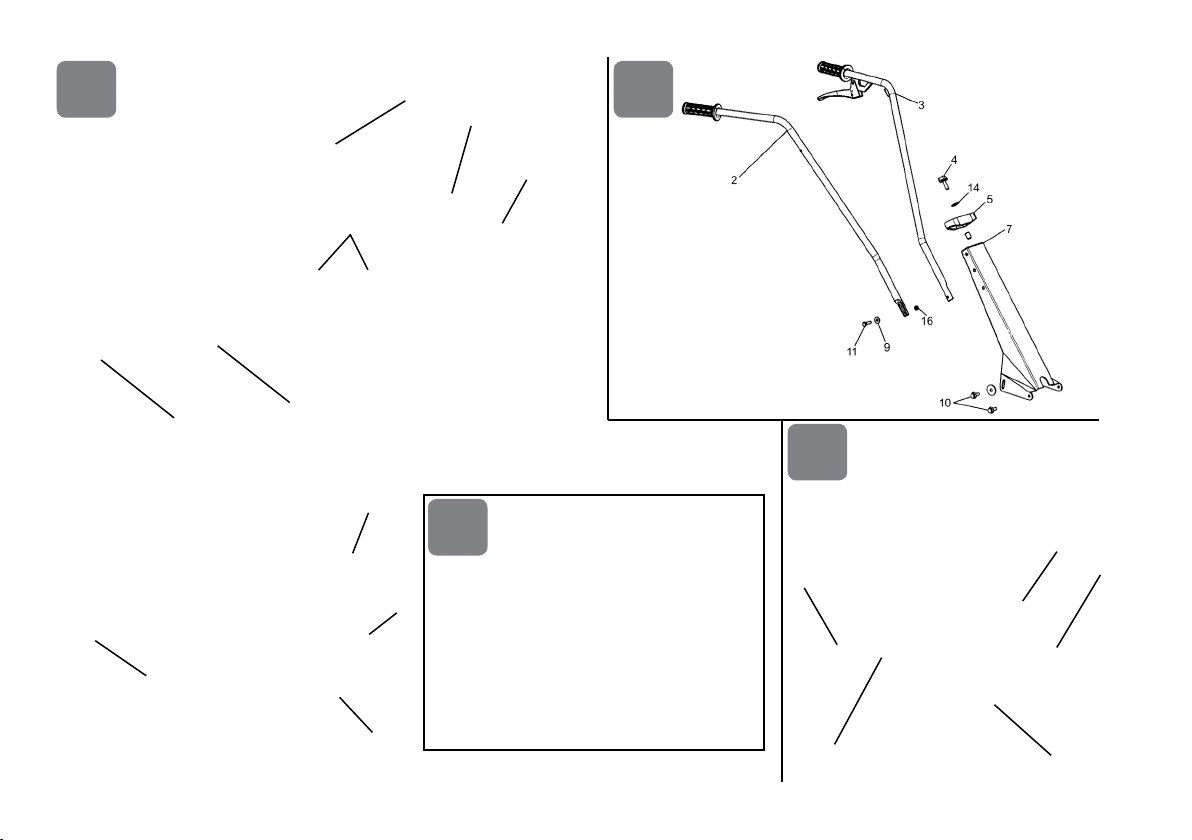
nTRASPORTO Per la movimentazione è previsto l’uso di carrello elevatore. Le forche, allargate al massimo consentito, vanno inserite negli
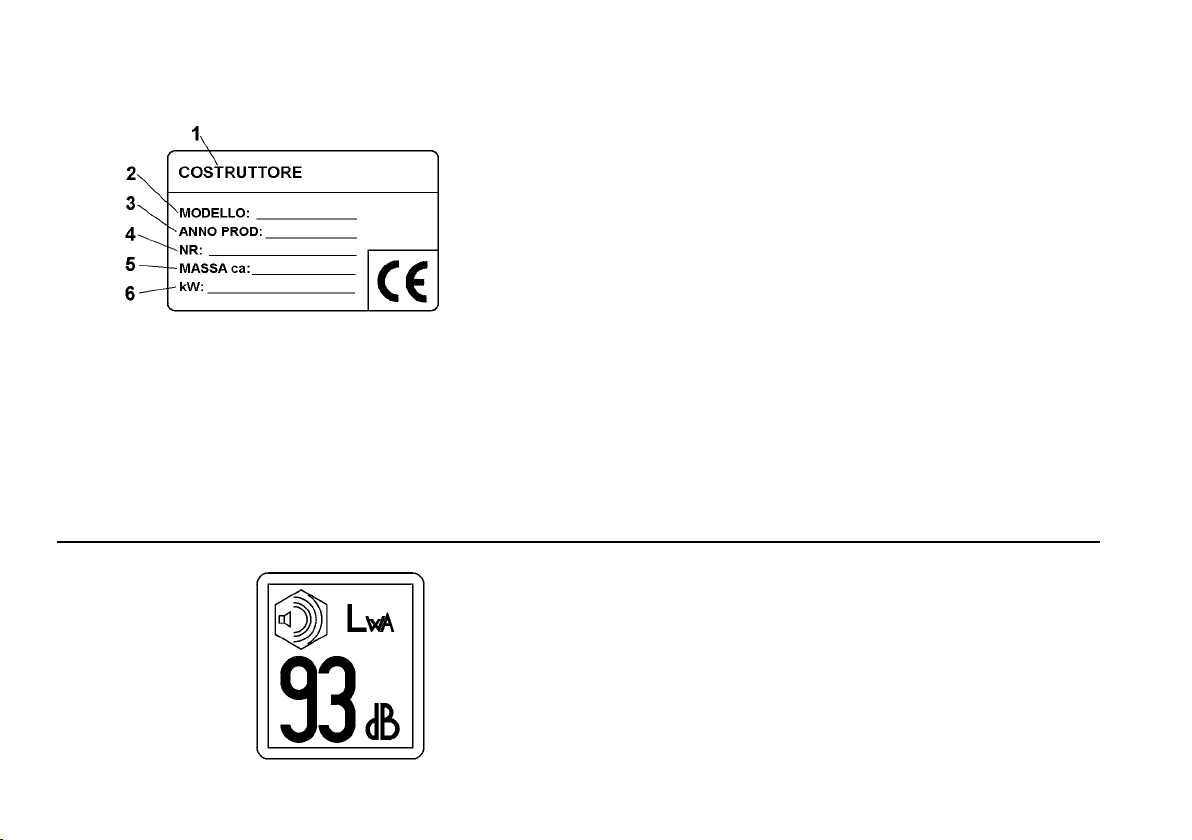
appositi spazi del pallet. La massa della macchina è indicata nella etichetta della marcatura e riportata nei dati tecnici. Tramite la ruota di trasferimento
(Fig. 1 part. E) è possibile portare la motozappa nella posizione di impiego in modo pratico e comodo. Prima di trasportare la macchina spegnere il
motore.
ITALIANO
2

nMONTAGGIO (Fig.1-2) Per motivi di trasporto la macchina non è completamente montata. Montare la ruota e bloccare il supporto ruotino al
telaio con la vite ad aletta. Montare lo sperone (G) e bloccare con la coppiglia (I). Per fresare invece è necessario togliere la ruota (E). Fig.2 Fissare
il supporto stegola (7) al telaio con le 4 viti M 6 (10) e rondelle. Avvitare nei fori e per ultimo, serrare a fondo tutte le altre viti del telaio.
nMONTAGGIO STEGOLE (Fig. 2) Inlare i tubi stegola (2 e 3) nei fori del particolare 5; quindi ssarli al supporto (7) con 2 viti M6 (11),
rondelle (9) e 2 dadi auto bloccanti (16). Serrare a fondo con la vite (4) e rondella (14).
Messa in moto delle frese (Fig.1a): impugnare il manubrio (B) e premere il fermo di sicurezza (M) che impedisce l’innesto accidentale delle
frese. Tirare la leva avanzamento (A) per tutta la sua corsa.
Per arrestare il movimento delle frese : lasciare la leva avanzamento (A).
nMONTAGGIO ACCELERATORE (Fig. 3) Il lo acceleratore è già montato sia sul motore che all’interno del dispositivo acceleratore (3).
Tale dispositivo va ssato nel foro (A) del manubrio con la vite (2) e bloccato con il dado (1) avendo cura di controllare che il manettino acceleratore
(4) si muova liberamente.
nREGOLAZIONE DEL FILO AVANZAMENTO si effettua a agendo sul registro (L) posizionato in prossimità della leva (A) Fig. 1.
nREGOLAZIONE STEGOLE (g. 2) Si può adattare l’altezza della stegola secondo l’altezza dell’utilizzatore. Per variare l’altezza agire
sulle viti di regolazione (10).
nREGOLAZIONE PROFONDITÀ DI LAVORO Agendo sullo sperone si può regolare la profondità di lavoro da cm 5 a 12. Togliere la
copiglia, regolare l’altezza dello sperone e rimettere la coppiglia. La posizione più bassa dello sperone corrisponde alla minore profondità di lavoro.
La posizione più alta corrisponde alla maggiore profondità di lavoro.
nCONTROLLO PRIMA DELL’USO ATTENZIONE prima di avviare il motore controllare sempre che la macchina sia in perfette
condizioni di funzionamento. IMPORTANTE : al primo utilizzo della macchina è assolutamente necessario vericare che all’interno del
telaio sia presente l’olio di lubricazione. Non avviare la macchina senza avere prima fatto questo controllo. Terminato il montaggio
accendere la motozappa e controllare che, portando l’acceleratore in posizione stop, il motore si spenga correttamente.
Per vericare il livello olio: Mettere la macchina in piano. Svitare il tappo e controllare che l’olio sia al livello inferiore del foro. Olio: SAE 80 per
trasmissioni.
nFUNZIONAMENTO Avviare il motore, mettere le frese a contatto del terreno, premere sulle stegole per forzare lo sperone contro il terreno
e tirare la leva avanzamento. La fresa penetra nel terreno, graduando la pressione sulle stegole e quindi sullo sperone, la macchina avanza. Per
trasportare la motozappa in macchina si possono piegare le stegole.
ITALIANO
3

nMANUTENZIONE Vericare il livello olio. Sostituzione olio del cambio (solo per motori/cambi a caldo) In linea di massima si dovrebbe
sostituire l’olio ogni 60 ore di lavoro; utilizzare olio SAE 80 per trasmissioni, circa 0,25 litri. Cambio olio: a) Allentare il tappo a vite. - b) Collocare
la macchina in posizione inclinata e far deuire l’olio. - c) Introdurre l’olio nuovo. Livello dell’olio no al bordo inferiore del foro di riempimento. - d)
Richiudere il foro di riempimento con il tappo a vite.
IMPORTANTE! Per evitare l’inquinamento delle falde acquifere, l’olio esausto non deve essere gettato in scarichi fognari o canali idrici. Depositi
per l’olio esausto sono ubicati presso tutti i distributori di benzina, oppure in discariche autorizzate secondo le normative comunali del Comune di
residenza.
Filtro aria e candela: rispettare le istruzioni del costruttore del motore.
Cambio frese. Montando le frese, la parte tagliente dei coltelli deve essere orientata nel senso di rotazione asse frese.
nPULIZIA Non procedere alla pulizia con il motore in moto. Attenzione ai coltelli fresa. Mantenere serrati tutti i dadi, i bulloni e le viti per
garantire il funzionamento della macchina in condizioni di sicurezza. Non immagazzinare mai la macchina con benzina nel serbatoio all’interno di
un edicio dove i vapori possono raggiungere una amma libera od una scintilla e comunque lasciar raffreddare il motore prima di immagazzinarla
in qualunque ambiente chiuso. Svuotare il serbatoio all’esterno. Per ridurre il pericolo di un incendio, mantenere il motore, il silenziatore e la zona di
immagazzinamento della benzina liberi da erba, foglie o grasso eccessivo.
nDESCRIZIONE DEI COMANDI (Fig. 1) A. Leva avanzamento. - B. Stegola - C. Manetta comando acceleratore a mano. - D. Motore - E.
Ruota trasporto. - F. Supporto stegola regolabile - G. Sperone - H. Fresa - I. Copiglia.
nCARATTERISTICHE TECNICHE Larghezza di lavoro 35 cm - Giri fresa 120-1 - Massa circa 25 Kg. - Carburante benzina - Capacità
serbatoio 1.0 L. - Per altri dati tecnici e particolari del motore, vedere l’allegato manuale di istruzioni dello stesso.
nRUMORE AEREO E VIBRAZIONI Valore di pressione acustica al posto di lavoro secondo EN 709 Leq = 80,5 dB(A), valore d’incertezza
nella misura K = ± 1,1 dB(A). Valore di potenza acustica secondo direttiva 2000/14/CE Lwa = 92,3 dB(A), valore d’incertezza nella misura K = ±0,7
dB(A). Vibrazioni alle stegole secondo EN 709 e ISO 5349= 4,39 m/s2, valore d’incertezza nella misura K = ±1,76 m/s2.
nACCESSORI A RICHIESTA Fresa cm. 16: per una facile zappatura in stretti lari - Risanatore prato a molle: ideale per eliminare feltro e
muschio da prati e giardini - Arieggiatore a lame: utile accessorio per la cura del prato, le lame praticano piccoli solchi nel terreno che ne permettono
l’aerazione - Rincalzatore o assolcatore: si usa per fare dei piccoli solchi nel terreno prima della semina.
La fresa e l’arieggiatore si ssano sull’ albero porta frese con vite M8 e dado, dopo aver smontato la fresa standard (cm. 36). Il risanatore prato a
molle va ssato all’albero porta frese con una spina elastica dopo aver smontato la fresa standard. Il rincalzatore, invece, si ssa alla macchina al
posto dello sperone e si blocca con una spilla a “r”. E’ severamente vietato utilizzare accessori che non siano quelli sopra citati. Attenzione al senso
di rotazione degli utensili.
ITALIANO
4

ITALIANO
5
nGUASTI
Prima di effettuare qualsiasi operazione, staccare il cappuccio della candela !
Guasto Rimedio
Il motore non si avvia Carburante esaurito, fare rifornimento.
Controllare che l’acceleratore sia posizionato su START.
Controllare che il cappuccio candela sia ben inserito.
Controllare lo stato della candela ed eventualmente sostituire.
Controllare che il rubinetto del carburante sia aperto (solo per i modelli di motore
in cui è previsto il rubinetto).
La potenza del motore diminuisce Filtro aria sporco, pulirlo.
Controllare che sassi o residui di terra e vegetazione non frenino la rotazione
delle frese, nel caso rimuoverli.
Le frese non ruotano Regolare i registri del cavo trasmissione.
Controllare che le frese siano ssate all’albero.
Nel caso non si riesca a porre rimedio al guasto, rivolgersi ad un centro di assistenza autorizzato.

Inhaltsverzeichnis
Einleitung
Einsatzbedingungen
Sicherheitsmaßnahmen
Bedienungshinweise
Transport
Montage
Einstellung
Wartung
Technische Daten
Lärmemission
Zubehörteile
Störung
Große Gefahr für den
Benutzer und die Personen
in Reichweite der
Maschine.
Einleitung
Verehrter Kunde,
wir bedanken uns für Ihr Vertrauen, das Sie in unseren Qualitätsprodukten entgegebringen und wünschen
Ihnen viel Freude beim Arbeiten mit Ihrem neuen Gerät. Um eine zuverlässige Inbetriebnahme von vornherein
zu gewährleisten,haben wir diese Betriebsanleitung geschaffen. Wenn Sie die folgenden Hinweise genau
beachten, wird Ihr Gerät stets zu Ihrer vollsten Zufriedenheit arbeiten und sich durch eine lange Lebensdauer
auszeichnen. Unsere Geräte werden vor der Serienherstellung unter härtesten Bedingungen erprobt
und selbst während der Fertigung ständig strengen Kontrollen unterzogen. Dies gibt uns die Sicherheit
und Ihnen die Gewähr, stets ein ausgereiftes Produkt zu erhalten. Dieses Gerät wurde im Herstellerland
durch neutrale Prüfstellen nach strengen Arbeits-und Sicherheitsnormen geprüft. Zur Aufrechterhaltung
dieser Funktions- und Sicherheitsgewähr dürfen im Bedarfsfall nur Originalteile des Herstellers verwendet
werden. Der Benutzer verliert alle evtl. bestehenden Ansprüche, wenn er das Gerät mit anderen als den
Originalersatzteilen verwendet. Konstruktions-und Ausführungsänderungen vorbehalten. Bei Rückfragen oder
Ersatzteilbestellungen die Artikelnummer und die Erzeugnisnummer angeben.
nKENNZEICHNUNGSANGABEN Das Schild mit den Maschinendaten und der Seriennummer ist
auf der hinteren Abdeckung der Lenkholme aufgeklebt. Hinweis: Bei eventuellen technischen Beratungsfragen
oder bei Ersatzteilbestellungen die Kennummer der Maschine angeben.
nEINSATZBEDINGUNGEN - EINSATZGRENZEN Die Motorhacke ist entwickelt und gebaut
worden, um auf Bodenächen Hackarbeiten auszuführen.Sie darf nur mit Originalausstattung und den
Originalersatzteilen arbeiten. Jede Art von Benutzung, die von der hier beschriebenen abweicht, ist nicht
gestattet. Es führt nicht nur zum Verfall der Garantiegewährung, sondern stellt auch eine große Gefahr für den
Bediener und alle Personen in der Reichweite der Maschine dar.
nSICHERHEITSMAßNAHMEN
Achtung: Vor der Montage und Inbetriebnahme unbedingt Bedienungsanweisung beachten! Personen,
die mit der Gebrauchsanweisung nicht vertraut sind, dürfen das Gerät nicht benutzen.
1. Personen, die mit der Bedienungsanleitung nicht vertraut sind, Kinder, Jugendliche unter 16
Jahren, sowie Personen unter Alkohol-, Drogen- oder Medikamenteneinuss dürfen das Gerät nicht
bedienen.
2. Diese Maschine ist entwickelt worden, damit sie von einem einzelnen ausgebildeten Benutzer
verwendet werden kann. Vor Benutzung sicherstellen, dass keine Kinder in der Nähe sind (10 Meter).
3. Das Gerät ist nicht für grobsteinigen Untergrund geeignet. Achten Sie deshalb bitte auf Fremdkörper,
während Sie mit dem Gerät arbeiten. Nur bei Tageslicht arbeiten bzw. bei sehr guter künstlicher
Beleuchtung. Nur bei Tageslicht arbeiten bzw. bei sehr guter künstlicher Beleuchtung.
DEUTSCH
6
Übersetzung der originalen Betriebsanleitung

4. Bei der Inbetriebnahme oder während der Arbeit die Hände oder Füsse stets von den rotierenden Teilen fernhalten. Beim Starten des
Motors darf der Benutzer nicht vor das Gerät oder vor die Arbeitswerkzeuge treten. Zum Starten des Motors dürfen sich die Hackmesser nicht
drehen - Aus diesem Grund bitte den Antrieb ausschalten!
5. Die laufenden Fräsen bilden eine Gefahrquelle für die Füsse. Während der Arbeit immer feste Schuhe und lange Hosen tragen. Die
Maschine nicht benutzen, wenn Sie barfuss gehen oder Sandalen tragen.
6. Beim Fahren mittels Radsatz auf Wegen ist der Motor abzustellen und der Stillstand der Hackmesser abzuwarten.
7. Wartungs- und Reinigungsarbeiten am Gerät sowie das Verstellen des Bremsspornes oder Radsatzes dürfen nur bei stillgesetztem Motor
und Stillstand des Schneidwerkzeuges erfolgen, bzw. bei abgezogenem Zündkerzenstecker
9. Der durch die Führungsholme gegebene Sicherheitsabstand ist stets einzuhalten. Das Gerät nicht von der Seite fuhren oder seitlich
vortreten. Mit der Maschine gehen, niemals laufen.
10. Die Notwendigkeit einer fachmännischen l Überprüfung ist erforderlich, wenn z.B. durch Auffahren auf ein Hindernis das Gerät sofort zum
Stehen kommt .
11. Gerate mit Verbrennungsmotor dürfen wegen der damit verbundenen Vergiftungsgefahr keinesfalls in geschlossenen Räumen in Betrieb
genommen werden.
12. ACHTUNG: Benzin ist leicht entammbar, deshalb ist folgendes zu beachten: Den Kraftsstoff in entsprechende Behälter aufbewahren,
das Auffüllen (bzw. Entleeren des Behälters) ausschlieslich im Freien vornehmen und während der Arbeit nicht rauchen, die Deckel des
Benzintanks und –behälters immer richtig zuschrauben.
13. Falls Benzin herausläuft, den Motor nicht anlassen und das Fahrzeug von der Stelle fortbringen an der das Benzin herausgeossen ist.
Vermeiden Sie die Zündung einzuschalten, bis sich die Benzindämpfe nicht aufgelöst haben.
14. Der Auspuff sowie der Bereich um den Auspuff können bis zu 80°C. heiß werden. Achtung: Verbrennungsgefahr!
15. Wenn man auf Geländen mit abschüssigem Verlauf arbeitet ist beim Wechsel der Richtung mit höchster Sorgfalt vorzugehen. Es empehlt
sich trotzdem nicht auf sehr steilen Abhängen zu arbeiten und stets auf die Stützpunkte zu achten.
16. Niemals die Einstellung des Motorderhgeschwindigkeitseglers verstellen oder den Motor auf Übertouren laufen lassen.
17. Vor dem Einsatz der Maschine eine Sichtkontrolle vornehmen, um sicherzustellen, dass die Messer nicht verschlissen bzw. beschädigt
sind. Aus Sicherheitsgründen alle Messer und Maschinenteile ersetzen, die verschlissen oder beschädigt sind. Die defekten Schalldämpfer
ersetzen.
18. Wir weisen darauf hin, daß wir für Schaden, die damit im Zusammenhang stehen, daß. a) Reparaturen unsachgemäß, bzw. nicht Von
unseren autorisierten ServiceStellen durchgeführt, oder. b) bei einem Teileaustausch keine ORIGINAL - ERSATZTEILE verwendet werden,
nicht haften! Für Zubehörteile gelten die gleichen Be stimmungen.
nDAS ARBEITEN MIT DER HACKE Die Entwicklung der Gartenpegehacke entspricht den neuesten Erkenntnissen des biologischen
Gartenbaus. Tiefes Umgraben wie früher ist nicht mehr das richtige Konzept. Die bestehenden Regenwurmkulturen werden dadurch beeinträchtigt
und die - durch Mikroorganismen geförderte Humusbildung gestört. Biogärtner wissen, dass die Bearbeitung der wertvollen Humusschicht nur im
obersten Bereich (achgründig) erfolgen sollte! Mit der Gartenpegehacke wird die oft mühevolle Bodenbearbeitung zur leichten, angenehmen
Tätigkeit. Sie arbeitet zuverlässig auf kleinsten Flächen, in schmalen Beeten, zwischen Panzenreihen oder unter Sträuchern und Bäumen. Hier zeigt
die was in ihr steckt. Spielend leicht wird die Erde gelockert, Torf und Dünger eingearbeitet und Unkraut beseitigt. Die speziell geformten Hackmesser
sorgen für panzgerechte Feinkrümelung des Bodens. Die Arbeitstiefe wird mit dem Bremssporn eingestellt. Je weiter der Bremssporn nach unten
gestellt wird, desto tiefer greifen die Hackmesser (Arbeitstiefe von 5 - 12 cm).
DEUTSCH
7

nTRANSPORT Für den Transport der Maschine ist ein Gabelstapler zu benutzen. Die auf die höchstzulässige Breite gestellten Gabeln sind in
den Raum unter der Palette einzufahren. Das Gewicht der Maschine steht auf dem Typenschild und in den technischen Daten. Mit dem Transportrad
(Abb. 1 Teil E) ist die Motorhacke leicht und bequem zum Einsatzort zu rollen. Stellen Sie den Motor von dem Transport der Maschine ab.
nMONTAGE (Abb.1-2) Um den Transport zu vereinfachen, wird die Maschine unvollständig montiert zur Auslieferung gebracht. Bevor das
Gerät zum Einsatz kommen kann, Transportrad in die Trägerkonsole einführen und mit der Flügelschraube sichern. Dann Bremssporn (G) montieren
und mit Federstecker (I) sichern. Zum fräsen ist es notwendig Transportrad (E) abzumontieren. Abb.2 Holmhalter (7) an Konsole mit 4 Schrauben M6
(10), Scheiben befestigen und an den Langlöchern einschrauben.
Zuletzt die anderen Schrauben der Konsole gründlich klemmen.
nHOLMEN MONTAGE (Abb.2) Die Lenkholmrohre (2 und 3) in die Bohrungen von Teil 5 einstecken und am Träger (7) mit 2 Schrauben M6
(11), Unterlegscheiben (9) und zwei Selbstsperrenden Muttern (16) befestigen. Die Schraube (4) und ihre Unterlegscheiben (14) fest anziehen.
Um die Ingangsetzung der Fräse (Abb.1a): die Sicherungssperre (M) drücken, sodass die zufällige Einschaltung des Hacksatzes verhindert
wird und den Vorschubhebel ganz ziehen (A). Um die Fräsebewegung anzuhalten, den Gashebel (A) wieder lassen.
nMONTAGE DES GASHEBELS (Abb.3) Das Kabel des Gashebels ist bereits am Motor sowie im Inneren der Beschleunigungsvorrichtung
(3) montiert. Diese Vorrichtung muss in der Öffnung (A) der Lenkstange mit der Schraube (2) befestigt und mit der Mutter (1) gesichert werden,
gleichezeitig sich versichern dass den Hebel (4) frei sich bewegen kann.
Dei FEINEINSTELLUNG des Vorschubskabels führt man durch das An- oder Abschrauben der Reguliervorrichtung (L), die in der Nähe des Hebels
(A) Bild.1 liegt, durch.
nBEDIENUNGSHINWEISE - Einstellung der Oberholmhöhe (Abb.2) Die Oberholmhöhe sollte entsprechend der Körpergröße und den
entsprechenden Arbeitsbedingungen eingestellt werden. Durch Schwenken der Holmkonsole innerhalb des Langlochbereiches wird die Oberholmhöhe
eingestellt. Die normale Höheneinstellung entspricht der Hüfthöhe (10).
nEINSTELLUNG DER ARBEITSTIEFE Die Einstellung der Arbeitstiefe von ca. 5 - 12 cm erfolgt durch den Bremssporn. Federstecker
herausziehen. Bremssporn auf die gewünschte Arbeitstiefe stellen und mit Federstecker wieder sichern. Bremssporn untere Stellung: geringe
Arbeitstiefe - Bremssporn obere Stellung: große Arbeitstiefe.
nÜBERPRÜFUNG VOR INBETRIEBNAHME
ACHTUNG Vor dem Starten des Motors immer sicherstellen, dass die Motorhacke
einen einwandfreien Betriebszustand aufweist.
WICHTIG: Bei dem ersten Gebrauch der Maschine ist es unbedingt notwendig zu prüfen,
dass das Schmierung Öl in dem Getriebe sich bendet. Die Maschine soll in keinem Fall eingeschaltet werden, bevor Sie diese Prüfung
durchgeführt haben. Nach der Montage die Maschine anlaufen lassen und prüfen, beim bringen den Gashebel in Stop-Stellung, dass den
Motor richtig abstellt.
Ölstand im Schneckenantrieb überprüfen. Motorhacke auf ebenen Boden stellen. Ölverschlußschraube herausdrehen (mit Inbusschlüssel SW 7).
Ölstandshöhe: bis Unterkante der Einfüllöffnung. Ölsorte: Getriebeöl SAE 80. Getriebeölwechsel (nur bei warmen Motor/Getriebe) Grundsätzlich
DEUTSCH
8

sollte alle 60 Arbeitsstunden auch das Getriebeöl gewechselt werden. (Ölviskosität SAE 80). Ölwechsel: a) Verschlußschraube lösen. b) Gerät
schräg stellen und Öl ablaufen lassen. c) Neues Öl einfullen. Ölstandhöhe bis Unterkante Einfüllöffnung mit Verschlußschraube wieder schließen. d)
Einfüllöffnung mit Verschlußschraube wieder schließen.
ACHTUNG! Altöl nicht ins Kanalnetz oder Erdreich ablassen. Grundwasserverschmutzung wird streng bestraft. Altölannahmestellen sind alle
Tankstellen bzw. nennt Ihnen jede kommunale Behörde.
nARBEITSFUNKTION Bei laufendem Motor Hackmesser auf die Erde aufsetzen, das Gerät festhalten und den Bremssporn in den Boden
drücken. Kupplungshebel am Holm spannen. Die Hackmesser graben sich nun in die Erde. Wenn Sie jetzt die Hacke an den Holmen etwas anheben,
arbeitet das Gerät vorwärts. Der Bremssporn soll beim Arbeiten immer in der Erde sein. Zum Transport des Gerätes in einem Auto, PKW-Anhänger,
usw., können die Oberholme umgeklappt werden. Hierzu Flügelschraube am Holmkopf abschrauben. Bowdenzug aus der Einhängenase aushängen.
Holmkopf etwas nach oben schieben und Oberholme umlegen.
nWARTUNG Ölstand im Schneckengetriebe regelmäßig überprüfen. Ölwechsel nach jeweils 60 Betriebsstunden. Ölsorte: Getriebeöl SAE
80 - ca. 0.25 l. Luftlter - Zündkerze. Bitte beachten Sie die Betriebsanleitung des Motorenherstellers, welche dem Gerät beiliegt. Auswechseln der
Hackmesser: Hackmesser - Spannstifte mit dem (im Lieferumfang der Hacke enthaltenem) Splinttreiber austreiben (ausschlagen). Hackmesser
abziehen. Achtung: Beim Einbau der Hackmesser auf richtige Position achten. Die angeschliffenen Flanken der Hackmesser müssen in Drehrichtung
der Achswelle sein. Achten Sie darauf, daß sich die Hackmesser - Spannstifte wieder an ihrer ursprünglichen Position benden.
nREINIGUNG UND WARTUNG Reiniguns - und Wartungsarbeiten dürfen nur bei stillgesetztem Motor und abgezogenem Zündkerzenstecker
vorgenommen werden! Reinigung: Gerät nach jedem Gebrauch reinigen. Sicherstellen, dass alle Muttern, Schrauben und Bolzen fest zugeschraubt
sind, um die sicherheitsgerechte Funktionsweise der Maschine zu gewährleisten. Wenn Benzin im Tank vorhanden ist, die Maschine niemals in
Gebäude lagern, wo die Benzindämpfe mit offenen Flammen oder Funken in Berührung kommen könnten. Den Motor abkühlen lassen, bevor man
die Maschine in geschlossenen Räumen abstellt. Das Entleeren des Benzintankes sollte nur im Freien erfolgen. Um Brandgefahr zu vermeiden den
Motor, den Schalldämpfer und den Lagerraum von Gras, Blättern und Fett befreien.
nBESCHREIBUNG DER BEDIENUNGSELEMENTE (Abb.1) A) Kupplungshebel - B) Lenkholme - C) Gashebel - D) Motor - E)
Transportrad - F) Holmhalter höhenverstellbar - G) Bremssporn - H) Hackmesser - I) Federstecker.
nTECHNISCHE DATEN Arbeitsbreite: 35 cm - max. Drehzahl der Hackmesser: 120 min-1 - Masse ca 25 kg. - Kraftstoff : 4 Takt Benzin -
Kraftstofftank: Inhalt ca. 1,0 l - Weitere Daten u. Hinweise zum Motor: siehe beillegendes Handbuch des Motorenhestellers.
nLÄRMEMISSION UND VIBRATIONEN Schallleistungspegel laut Richtlinie En 709, Leq = 80,5 dB(A), Messunsicherheit K = ±1,1 dB(A).
Höchstzulässige Schallwerte ist LWA = 92,3 dB(A), Messunsicherheit K = ±0,7 dB(A).
Höchstzulässigevibrationen an den Lenkholmengemäß EN709 und ISO5349. Meßwert in = 4,39 m/s2, Messunsicherheit K = ±1,76 m/s2.
nZUBEHÖRE AUF ANTRAG Fräse cm. 16: für ein einfaches Hacken in engen Reihen - Der Federrechen : ideal, um Fasern und Moos
von Rasen und Gärten zu entfernen - Lüfter mit Messern: nützliches Zubehör für die Pege des Rasens, die Messer führen kleine Furchen in
DEUTSCH
9

DEUTSCH
10
den Boden aus, um dessen Belüftung zu erlauben - Häuer oder Reihenzieher: dadurch werden kleine Furchen in den Boden vor der Aussaat
ausgeführt. Die Fräse und der Lüfter werden an der Fräsen-Welle durch eine Schraube M8 und eine Mutter angebracht, nachdem die Standardfräse
abmontiert worden ist (cm. 36). Der Federrechen wird auf der Hackwellenachse montiert und durch einen Spannstift befestigt, aber nachdem die
Hackwerkzeuge demontiert geworden sind. Der Häuer wird dagegen an der Maschine anstelle von dem Bremssporn angebracht und wird durch
eine “r” Nadel blockiert. Die Verwendung von Zubehören, die anders als die oben genannten sind, ist streng verboten. Auf die Drehungsrichtung der
Werkzeuge aufpassen.
nSTÖRUNG
Vor allen Wartungs- und Reinigungsarbeiten Zündkerzenstecker abziehen!
Störung Beseitigung
Motor springt nicht an Benzin auftanken.
Gashebel auf Position “START” stellen.
Zündkerzenstecker auf die Zündkerze aufstecken.
Zündkerze überprüfen, eventuell erneuern.
Kraftstoffhahn aufdrehen (nur für Motoren mit Kraftstoffhahn).
Motorleistung lässt nach Luftlter reinigen.
Hackmesser von verrotteten Panzenresten reinigen.
Hackmesser drehen nicht Bowdenzug nachstellen.
Hackmesser auf der Getriebwelle lose.
Störungen, die mit Hilfe dieser Tabelle nicht behoben werden können, dürfen nur durch einen autorisierten Fachbetrieb behoben werden.

List of contents
Introduction
Conditions of use
Safety measures
Instructions for operating
Transport
Assembly
Regulating
Maintenance
Technical Details
Noise
Accessories
Fault
Serious risk for operator
and bystander safety.
Introduction
Dear Customer,
Thank you for your trust in purchasing our products. We wish you to enjoy using our machines.
The following working instructions have been issued to ensure you a reliable operation from the beginning.
If you carefully follow such information the machine will operate with complete satisfaction and have a long
service life. Our machines are tested under the most severe conditions before being put into production and
are subject to strict continuous test during manufacturing stages.
This unit has been tested in the country of origin by independent testing authorities in accordance with strict
work norms and safety standards.
When required, only original spare parts must be used to maintain guaranteed functions and safety level.
The operator forfeits any claims which may arise if the machine shows to be tted with components other than
original spare parts.
Subject to changes in design and construction without notice.
For any questions or further information and spare parts orders, we need to be informed of the unit of the unit
serial number printed on the side of the machine.
n IDENTIFICATION DATA
The decal with the machine data and Serial N° is glued onto the rear of the handlebar cover. Please - Always
state your motor cultivator serial number when you request Technical Service or Spare Parts.
nCONDITIONS AND LIMITATIONS OF USE
This motor-hoe is designed and built to hoe the land. The motor-hoe must only be used with original equipment
and spares. Any use other than those described above is prohibited and will involve, in addition to cancellation
of the warranty, serious risk for the operator and bystanders.
nSAFETY PRECAUTIONS
Attention: Before assembly and putting into operation, please read carefully the operating instructions. Persons
not familiar with these instructions should not use the machine.
1. Persons who are not familiar with the operating manual, as well as children, adolescents under
the age of 16 and persons under the inuence of alcohol, drugs or medication must not operate the
mower.
2. The unit was designed in order to be used by 1 trained operator only. The person using the mower is
responsible for any accidents involving other persons or their property. When operating the machine,
the user should ensure that no others, particularly children, are standing in the area (10 mt.).
3. Do not use the machine on terrain which contain large stones. Look out for foreign bodies in the soil
while you are using the machine. Work only in daylight or in good articial light.
ENGLISH
11
Translation of original user instructions

4. When switching on or operating the machine, do not put your hand or feet near or under rotaring parts. When starting the engine, the
operator should not stand in front of the machine or in front of the work tools. When pulling the engine cord for startup, the tiller should not
rotate (if rotation is experienced, take action on the belt stretcher control nut).
5. As the cultivator blades may cause injury to your feet, wear strong shoes and long trousers, when working. Do not work when barefoot or
wearing open sandals.
6. When running the machine on its set of wheels on a path, switch off the motor and wait until the cultivator blades stop.
7. Maintenance and cleaning work on the machine, as well as adjustment of the brake shoe or set of wheels, must only be carried out with
the motor switched off and the cutting tool stopped. Remove the sparkplug .
8. When leaving the machine or leaving the guide handles the motor should be switched off.
9. The safety margin provided by the guide handles should always be observed. Do not guide the machine from the side or walk in front or to
the side of the machine whilst in operation. Walk, never run with the machine.
10. It is essential to have the machine checked professionally if it comes to a sudden stop, for example, as a result of hitting an obstacle .
11. Machines with an internal combustion engine must never be operated in closed rooms because of poisoning danger.
12. WARNING: Petrol is highly ammable, store fuel in containers specically designed for this purpose, refuel outdoors only and do not
smoke while refuelling, replace all fuel tank and container caps safely.
13. If petrol is spilled, do not attemp to start the engine but move the machine away from the area of spillage and avoid creating any source
of ignition until petrol vapours have dissipated.
14. The exhaust and parts close to it can heat up to 80° Celsius. Attention: Burnhazard!
15. Be cautions when working on slopes and changing direction, however do not operate on too steep slopes, always ensure of your
footing.
16. Do not change the engine governor settings and do not overspeed the engine.
17. Before using, always inspect the tools to see if they are worn or damaged. Replace worn or damaged elements. Replace faulty
silencers.
18. Please note that our company assumes no responsibility for damages due to: a) repairs made by unspecialized personnel or unauthorized
after-sales service centers, or. b) use of other than ORIGINAL SPARE PARTS. The same conditions apply to the accessories.
nWORKING WITH THE CULTIVATOR The development of the garden cultivator corresponds to the latest ndings in biological horticulture.
Deep turning over of the earth as was previously done is not the right concept. The existing earthworm cultures are disturbed by doing this and the
build up of humus, stimulated by micro organisms, destroyed. Bio-gardeners know that only the topmost layer of the valuable humus should be
worked. With the garden cultivator, the often laborious job of earth working becomes a pleasant, easy task. It works reliably in the smallest areas, in
narrow beds, between rows of plants or under shrubs and trees. Here the really shows what it is made of. The earth is loosened up easily, peat and
fertilizers are worked in and weeds removed. The specially shaped cultivator blades ensure that the earth is crumbled up nely so that it is suitable
for plant growth. The working depth is adjusted via the brake rod. The further down the rod is set, the deeper the blades reach. (Working depth from
5 - 12 cm).
nTRANSPORT A forklift truck should be used to move the machine. The forks should be opened as far as possible and inserted into the pallet.
The weight of the machine is given on the Manufacturer’s data plate together with the other technical information. otor-hoe can be transported to given
place by means of transport wheel (Fig 1 part. E). Switch off the engine before transporting the machine.
ENGLISH
12

nASSEMBLY (g.1-2) To facilitate the transport, the machine is supplied incompletely mounted. Assemble the wheel and lock the bearing
wheel to the frame/chassis using the wing nut. Assemble the root face (G) and secure it with the cotter pin (I). To use rotavators/to cultivate it is
necessary to disassemble the wheel (E). Fig.2 Fix the handlebars support (7) to the frame with the 4 screws M6 (10), washers and screw them into
the holes. Last, tighten all the other screws all the way.
nHANDLEBARS ASSEMBLY (g.2) Push the handlebar tubes (2 and 3) into holes in part.(5). Next x them to the mounting (7) using 2
M6 screw (11), Ø 6 washers (9) and two self-locking nuts (16). Tighten screw (4)all the way with its corresponding washer (14).
To switch the cultivator blade (Fig.1a): Grip the handlebars (B) and press the safety device (M) which is preventing the accidental tines
connection. Pull the forward lever (A) all its way long.
To switch off the cultivator blade, release the clutch lever (A).
nTHROTTLE ASSEMBLY : (Fig. 3) The throttle cable is already assembled both on the engine and inside the throttle device (3). Such
device should be tightened to hole (A) from the handlebar using a screw (2) and locked with nut (1) taking care to check the handle (4) to turn freely.
nThe adjustement of the forwarding cable can be performed working on the adjuster (L) which is placed closed to the lever (A) g.1.
nOPERATING INSTRUCTIONS Adjusting the height of the upper handle (Fig. 2) The height of the upper handle should be adjusted
according to the size of the person and the relevant working conditions. By tilting the handle console within the area of the oblong holes, the height
of the upper handle can be adjusted (10). The normal height setting should be hip height.
nADJUSTING THE WORKING DEPTH The working depth can be set from ca. 5 - 12 cm. using the brake rod. Remove the plug. Set the
brake rod at the required working depth and secure back in position with the spring pin. Brake rod in lowest position: shallow working depth - Brake
rod in uppermost position: deep working depth.
nCHECKING BEFORE PUTTING INTO OPERATION ATTENTION ! Before switching the engine on, carefully check if the motor-
hoe is in perfect good repair. IMPORTANT: at the rst use of the machine it is absolutely necessary to verify that inside the chassis to be
present the lubrication oil. Do no start the unit/machine on before having done such control. When you have nished the assembly, switch
the motor hoe on and check , bringing the accelerator to stop position, the engine to shut completely down.
To Check the oil level :Stand the machine on horizantal position . Unscrew the oil plug and check the oil to be at the lower edge level of the lling hole.
nWORK FUNCTION With the engine running, position the blades on the soil: hold the machine rmly and press the brake rod into the ground.
Activate the clutch lever on the handle. The cultivator blades will now dig into the earth. If you slightly raise the cultivator by the handles, the machine
will go forwards. when working, the brake rod should always be in the earth. For transporting the machine in a car or on a trailer etc. the upper handles
can be folded down. To do this, unscrew the buttery screw on the shaft head. Unhook the throttle cable from the lug. Push the shaft head upwards
and fold the upper handles over forwards.
ENGLISH
13

nMAINTENANCE Regularly check the level of the oil in the worm gear unit. As a general rule the oil should be changed after every 60 work
hours. Type of oil: Gearbox oil SAE 80 - ca. 0,25 l. ( just for warm engines/gearboxes) . To change oil: a) loosen the oil screw cap. b) put the machine
on inclined position and make the oil to ow completely out . c) Add the new oil until it reaches the bottom edge of the ller hole. d) close the lling
hole again using the oil screw plug.
ATTENTION! The used oil must not be drained into the sewer system or waterworks. In order to prevent any pollution to the water-table. Most garages
have used oil deposits, or use the authorized deposits according to your local authority regulations.
Replacing the cultivator blade: Knock out the roll pin. Remove the blade. Attention: When replacing the blade, check that it is correctly positioned.
The ground edges of the blades must be in the same turning direction as the axle shaft.
nCLEANING AND MAINTENANCE Cleaning and maintenance work should only be carried out with engine switched off and spark plug
removed! Cleaning: Clean the machine each time after use. Warning! Risk of injury from blades - always wear protective gloves. Keep all nuts, bolts
and screws tight to ensure the equipment is in safe working condition. Never store the machine with fuel in the tank inside a building where fumes can
reach an open ame or spark and however allow the engine to cool before storing indoors. The fuel tank is to be drained outdoors only. To reduce the
re hazard, keep the engine, silencer, battery compartment and fuel storage area free of grass, leaves and excessive grease.
nDESCRIPTION OF CONTROLS (Fig. 1) A) Clutch lever - B) Handlebar - C) Throttle lever - D) Engine - E) Transportation wheel - F)
Handle retainer - G) Brake rod - H) Cultivator blade - I) Spring pin.
nTECHNICAL DETAILS Working width 35 mm - max. speed of blade -120 min -1 - Mass approx. 25 kg. - Fuel 4 stroke petrol - Fuel tank
contents approx. 1.0 L. - Please consult the relative instruction manual for other technical information and details about the engine.
nNOISE AND VIBRATION LEVEL Measured sound pressure level with En709, Leq = 80,5 dB (A), with a uncertainty value K = ±1,1 dB (A).
Measured sound power level with 2000/14/CE, Lwa = 92,3 dB (A), with a uncertainty value K = ±0,7 dB (A).
Handlebar vibration in compliance with EN 709 and ISO 5349. Level max detected = 4,39 m/s2, uncertainty value K = ±1,76 m/s2.
nAVAILABLE ACCESSORIES Rotavators cm. 16: it is easy to use it for an easier hoeing on narrow rows - De-thatcher: it is good to
eliminate the grass entanglement and musk from elds and gardens – Aerator: it is a good tool for your own garden care as the blades can make
little furrows into the ground and aereate it - Ridging plough: it is necessary to use it to cut small furrows before sowing.
The rotavators and aerator can be assembled on the rotavators-holder shaft with screw M8 and nut , after having disassembled the standard pin
(cm. 36) . The de-thatcher has to be xed on the hob spindle of the machine with an elastic plug, after the disassembling of the standard cutter. The
ridging-plough , on the contrary can be assembled to the machine instead of the spur and can be xed with a “r” pin. It is absolutely forbidden to use
tools/equipment other than the above described ones. Pay attention to the tools rotating direction.
ENGLISH
14

ENGLISH
15
nTROUBLESHOOTING
Before performing any maintenance and clearing work operation , please take the spark-plug cap off.!
FAULT FAULT CLEARANCE
The engine does not start Check the fuel level, if necessary refuel.
Check the throttle to be on START position.
Check the spark-plug connector to be properly attacched.
Check the spark-plug condition and if necessary replace it.
Check the fuel valve to be in the opened position( only for the models showing
such feature).
The engine power goes down The air lter is dirty – please clean it.
Check if any stone or soil/vegetation residue is stopping the tines rotation, in case
clean them.
The tines are not rotating Adjust the transmission cables registers.
Check the tines to be fasten to the shaft.
In case you are not able to remedy the defect/damage according to a.m. table, please contact an authorized service center only .
Table of contents
Languages:
Other STERWINS Tiller manuals