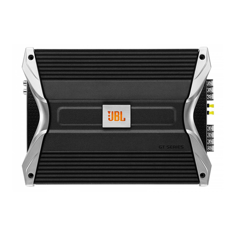
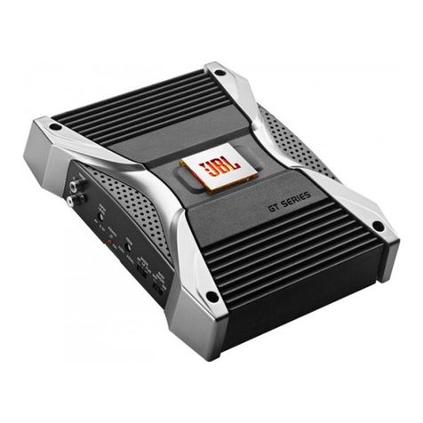
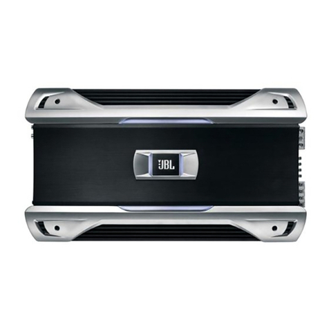
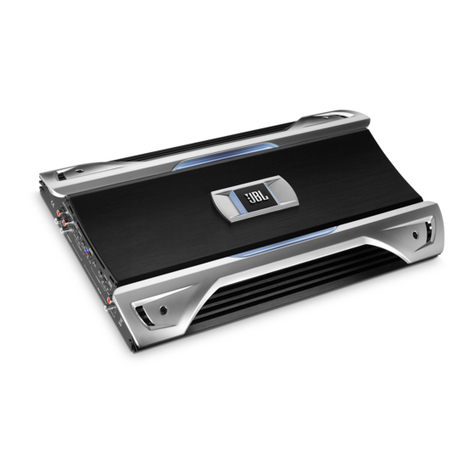
JBL GTS100X User manual

GRAND TOURING SERIES
2/1 Channel
Automotive Power Amplifier
GTS100x Owner’s Manual
GENUINE JBL
GTS100x OM 7/16/98 2:56 PM Page 1

02
Introduction . . . . . . . . . . . . . . . . . . . . . . . . . . . . . . . . . . . . . 3
Features . . . . . . . . . . . . . . . . . . . . . . . . . . . . . . . . . . . . 4
About Installation . . . . . . . . . . . . . . . . . . . . . . . . . . . . . 4
Quick Start . . . . . . . . . . . . . . . . . . . . . . . . . . . . . . . . . . . . . . 5
System Design Using the GTS100x . . . . . . . . . . . . . . . . . . . . . 6
Speakers . . . . . . . . . . . . . . . . . . . . . . . . . . . . . . . . . . . . 6
Signal Sources . . . . . . . . . . . . . . . . . . . . . . . . . . . . . . . 6
Other Components . . . . . . . . . . . . . . . . . . . . . . . . . . . . 7
Typical Applications . . . . . . . . . . . . . . . . . . . . . . . . . . . 8
Installation and Use . . . . . . . . . . . . . . . . . . . . . . . . . . . . . . . 10
Installation Precautions . . . . . . . . . . . . . . . . . . . . . . . . . 10
Physical Installation . . . . . . . . . . . . . . . . . . . . . . . . . . . 11
Controls and Connectors . . . . . . . . . . . . . . . . . . . . . . . . 12
Mounting Instructions . . . . . . . . . . . . . . . . . . . . . . . . . . 13
Wiring . . . . . . . . . . . . . . . . . . . . . . . . . . . . . . . . . . . . . . 14
Power Supply Connections . . . . . . . . . . . . . . . . . . . . 15
+12V Battery Wire . . . . . . . . . . . . . . . . . . . . . . . . . . 15
Ground Wire . . . . . . . . . . . . . . . . . . . . . . . . . . . . . . 15
Remote Turn-On Wire . . . . . . . . . . . . . . . . . . . . . . . 16
Audio Input Connections . . . . . . . . . . . . . . . . . . . . . . . . 17
Line-Level Input Connection . . . . . . . . . . . . . . . . . . 17
Input-Mode Switch . . . . . . . . . . . . . . . . . . . . . . . . . 17
Speaker-Level Input Connections . . . . . . . . . . . . . . . 18
Simultaneous Speaker-Level and Line-Level Inputs . 19
Speaker Connections . . . . . . . . . . . . . . . . . . . . . . . . . . . . . . . 20
Operation . . . . . . . . . . . . . . . . . . . . . . . . . . . . . . . . . . . . . . . 23
Gain Adjustments . . . . . . . . . . . . . . . . . . . . . . . . . . . . . 23
Other Characteristics . . . . . . . . . . . . . . . . . . . . . . . . . . 24
Solving Noise Problems . . . . . . . . . . . . . . . . . . . . . . . . . . . . . 26
Maintenance . . . . . . . . . . . . . . . . . . . . . . . . . . . . . . . . . . . . . 29
Additional System Configurations for Add-On or Upgrade . . . 30
In Case of Difficulty . . . . . . . . . . . . . . . . . . . . . . . . . . . . . . . . 32
Specifications . . . . . . . . . . . . . . . . . . . . . . . . . . . . . . . . . . . . 34
Warranty Terms . . . . . . . . . . . . . . . . . . . . . . . . . . . . . . . . . . 35
Owner’s Warranty Information
Model Number
Serial Number
Dealer Name
City, State, Zip
Sales Receipt Number
Date of Purchase
GTS100x OM 7/16/98 2:56 PM Page 2

03
Thanks for purchasing your new
GT series automotive amplifier.
The GT series amplifier you have
chosen includes many unique
features to enhance its perfor-
mance and utility. The power
amplifier circuitry is a fully dis-
crete design notable for low
distortion and unusually clean
and clear reproduction quality.
Your GT series amplifier will
easily connect to virtually any
car audio system, whether it is
factory installed or purchased
separately.
In addition to conventional pre-
amp-level inputs, this model fea-
tures JBL’s Universal Interface
design, which facilitates simple
connection to factory radios with
the low distortion that is usually
only associated with preamp-
level connection. With Universal
Interface, a factory radio can be
used either as the main music
source or combined with a CD
changer which includes volume
control capability, simulta-
neously connected directly to
the amplifier.
By providing this two-unit direct
connection, Universal Interface
circuitry eliminates the need for
an FM modulator to connect a
CD player to factory radios,
improving the fidelity of digital
playback.
Also, when using a high-powered
(BTL) radio through the
speaker-level inputs, Common
Sense turn-on circuitry senses
the common-mode voltage pre-
sent on the radio’s speaker wires
and turns the amplifier on with-
out an additional “remote” wire.
When the speaker-level inputs
are used exclusively, the
preamp-level inputs may be
converted to preamp-level
outputs to drive additional
amplifiers or signal processors.
In addition, the built-in active
crossover provides either high-
pass or low-pass operation. This
lets your GT series amplifier
power either subwoofer or main
speakers in a bi-amplified
system, without the expense of
an additional crossover.
Introduction
GTS100x OM 7/16/98 2:56 PM Page 3

04
• Gold-Plated RCA Input
Connectors
• Preamp Output Capability
• Convenient Easy-Disconnect
Power and Speaker Connections
• Third Order (18dB per Octave),
Capacitive/Inductive Power-
Supply Filtering
• Input Mode Switching
• Made in USA
About Installation
Although the GTS100x was
designed to make installation as
easy as possible, it is a sophisti-
cated product that requires
proper installation to realize its
full performance potential. Skill
with tools, an understanding of
basic electronics, and experience
with car stereo installation are
needed to properly install this
amplifier. If you feel you do not
have the necessary knowledge
and skills, we strongly recom-
mend that the installation be
done by your authorized JBL
dealer. If the GTS100x is
installed by a qualified JBL
dealer, we will double the length
of your warranty to two years
from date of purchase.
If you choose to install the
GTS100x yourself, read all of
the information in this manual
before you start the installation.
Pay particular attention to the
safety precautions and notes.
It will save potential problems
later if you take a few minutes
to plan the complete installation
before you start. The routing of
wires, the power supply connec-
tion points, and the mechanical
installation of the unit should be
completely thought out before
you begin. Work carefully and
check each step as it is per-
formed. Before operating the
amplifier, recheck the entire
installation to be sure that each
connection is correct, properly
insulated and secure.
Features
• Bridgeable 2/1 Channel
Operation
• Simultaneous Stereo +Mono
Operation
• Built-in Staggered 18dB/Octave
100Hz High-Pass and 80Hz Low-
Pass Crossover
• No Current Limiting
• Oversized Floating Rail
MOSFET Switch-Mode
Power Supply
• Common Sense 2-Way Turn-On
• Stealth Remote Silent Turn-On
Circuitry with Power-On
Indicator
• Continuously Adjustable
Gain Controls
• Capable of Single-Ended
Operation Into 2-Ohm Loads
• Fully Complementary, Direct-
Coupled, Discrete Power
Amplifier Circuitry
GTS100x OM 7/16/98 2:56 PM Page 4

05
Recommended for expe-
rienced professional
installers only!
1. Disconnect the negative cable
from the battery. Note: If the
vehicle’s radio features a
code-type security system,
make certain you know the
code before disconnecting
the battery!
2. Mount the amplifier to the
desired location using four
screws.
3. Run a minimum AWG #10
power cable complete with a
20-amp fuse (not included)
directly from the positive
+12V battery terminal to the
desired amplifier location.
Keep the fuse to within 5" of
the battery terminal, and
before the wire runs through
any metal partition.
Note: All wiring connections
should be made either by solder-
ing with heatshrink tubing insula-
tion or with high-quality crimp-
type insulated connectors
installed with a good crimping
tool. Soldering crimp connections
is recommended to further
enhance connection reliability.
Never use wire-nuts, insulation-
displacement connectors (i.e.,
ScotchLok type), or “twist and
tape” connections. Do not use
electrical tape; it will loosen with
age and extreme temperatures.
Never leave bare wire exposed.
4. Connect power wiring as
shown in the Wiring Diagram
on page 14, using the supplied
power harness.
5. Connect the outputs from the
signal source to the appropri-
ate inputs of the amplifier
according to the Wiring
Diagram (page 14) with either
high-quality low-level signal
cables with RCA plugs, with
the supplied speaker-level
input connector, or both.
6. Connect the speakers to the
amplifier according to the
wiring diagram on page 14.
7. Turn the input sensitivity
adjustment to the 1/4 position.
8. Set the input level switch to
“line” if you are using the line-
level (preamp) inputs.
9. Set the crossover switch as
desired.
10. Set the input mode switch to
stereo, left +right or right
input only operation.
11. Reconnect the negative bat-
tery cable.
12. Turn on the signal source at a
low volume level and check
for the correct output from
each speaker.
13. Adjust the amplifier gain con-
trol, using the procedure
described in the Gain
Adjustments section on
page 23.
14. Read the rest of the manual to
get maximum use and enjoy-
ment from your amplifier.
Quick Start
GTS100x OM 7/16/98 2:56 PM Page 5

06 When the GTS100x is in bridged
mode, the combined impedance
of the speaker (or speakers) con-
nected to the bridged channel
should be at least 4 ohms. As in
the example just mentioned,
sustained operation of the
GTS100x in bridged mode with
less than 4 ohms will likely cause
overheating. If monaural opera-
tion is desired, and two 4-ohm
speakers are used, it is best to
connect each speaker to an
individual amplifier channel
and use the “L+R” mode on the
input-mode switch to provide
monaural operation.
The GTS100x must not be used
with speakers that have either
one of their input terminals wired
to the frame of the speaker or to
the chassis of the vehicle.
Speakers
When used in the non-bridged
mode, the GTS100x can easily
drive 2-ohm speaker loads. When
only one speaker is connected to
each channel, virtually any com-
mon speaker may be used. When
two speakers are connected in
parallel to a given channel, each
speaker must have a minimum
impedance of at least 4 ohms to
ensure that the combined load
does not drop below 2 ohms.
Although the amplifier will not be
damaged, load impedances lower
than 2 ohms will eventually
cause the amplifier to overheat,
activating the protection circuits
and causing the unit to shut off
until it cools down sufficiently.
System Design Using the GTS100x
Signal Sources
The low-level preamp outputs of
any radio/tape deck, CD player
or preamp/ equalizer so equipped
can drive the GTS100x. The Gain
control of the GTS100x is used to
match the amplifier to the output
voltage of the source. This
matching is important to keep
noise low and is explained in the
Gain Adjustments section of this
manual (page 23).
Thanks to Universal Interface
circuitry, the GTS100x can also
be connected to power amplifiers,
radios or equalizers that are
equipped with only speaker
(+)
(-)
(+)
(-)
Parallel Wiring
Series Wiring
2 Ohms
Nominal
Impedance
8 Ohms
Nominal
Impedance
4 Ohms
4 Ohms
4 Ohms 4 Ohms
GTS100x OM 7/16/98 2:56 PM Page 6

07
outputs by connecting them
through the speaker-level input
connector. Inside the GTS100x,
the speaker-level and preamp-
level inputs are connected
through a mixing circuit, which
allows them to be used simultane-
ously. Therefore, a low-level
source, such as a CD player
equipped with preamp controls
(Volume, Balance, Bass, Treble)
may be connected to the preamp-
level inputs at the same time as a
powered radio/tape unit is con-
nected to the speaker-level
inputs. This provides a higher
performance alternative to an
FM Modulator connection when
Other Components
The system options of the
GTS100x are numerous. All JBL
amplifiers are designed with suffi-
cient adjustment range to match
with the accepted “normal”
voltages and impedances used
by virtually all car audio compo-
nents. With very few exceptions,
the GTS100x will match cor-
rectly to any equipment you
already have.
you wish to add CD capability to
a factory-installed cassette radio.
Switching from one source to the
other is as simple as turning the
desired source on and turning the
undesired one off — no additional
switches or relay connections
are needed.
GTS100x OM 7/16/98 2:56 PM Page 7

08 Typical Applications
The following diagrams show the
most common basic system con-
figurations using the GTS100x.
More elaborate systems are
formed by using a combination
of these “building blocks.” For
additional ideas, refer to the
“Additional System Configura-
tions for Add-On or Upgrade”
section on page 30.
LR
LRR
L– R+
– +
2 or 4-Ohm
Full-Range
Speakers or
Subwoofers
L– L+
– +
R– R+
– +
GTS100x
Application 1
Stereo Full-Range or Subwoofer Operation
Full-Range Operation
Subwoofer Operation
Crossover Input Mode Line
Switch Switch Switch
Off Stereo In
Crossover Input Mode Line
Switch Switch Switch
Low Stereo In
Main speakers are driven by head unit or additional amplifier.
Preamp or
Speaker-Level
Input
LR
4-Ohm
Full-Range
Speaker or
Subwoofer
4-Ohm
Full-Range
Speaker or
Subwoofer
Application 2
Bridge-Mode Operation
Single Amplifier:
Subwoofer Operation (Mono)
Main speakers are driven by head unit or
additional amplifier.
GTS100x
B
L– R+
– +
GTS100x
A
For Single Amplifier
Subwoofer Use
For Dual-Amplifier
Full-Range or Subwoofer Use
Preamp or
Speaker Level
Crossover
Switch
Low
Amp
B
Input Mode
Switch
L + R
Line
Switch
In
Dual Amplifier:
Subwoofer Operation (Stereo)
Full-Range Operation (Stereo)
Crossover
Switch
Low
Amp
A+B
Input Mode
Switch
R
Line
Switch
In
Crossover
Switch
Off
Amp
A+B
Input Mode
Switch
R
Line
Switch
In
GTS 10 0 x
CHANNEL POWER AMPLIFIER
GENUINE JBL
HIGH CURRENT 2/1
MADE IN USA
GTS 10 0 x
CHANNEL POWER AMPLIFIER
GENUINE JBL
HIGH CURRENT 2/1
MADE IN USA
GTS 10 0 x
CHANNEL POWER AMPLIFIER
GENUINE JBL
HIGH CURRENT 2/1
MADE IN USA
GTS100x OM 7/16/98 2:56 PM Page 8

09
L– L+
– +
L– R+
– +
R– R+
– +
R– R+
– +
L– R+
– +
L– L+
– +
Preamp or
Speaker-Level
Input
LR
2- or 4-Ohm
Full-Range
Speakers
LR
Front Rear
4-Ohm
Subwoofer
GTS100x
AGTS100x
B
Application 3
Biamplified, Three-Channel
Subwoofer/Satellite System
Amp Crossover Input Mode Line
Switch Switch Switch
A High Stereo In
B Low L + R In
Stereo Subwoofers may be used by configuring
GTS100x-B as shown in Application #1
Speaker-
Level
Input
L R R L
2- or 4-Ohm
Full-Range
Speakers
L R
Preamp
Output Preamp
Input
4-Ohm
Subwoofer
GTS100x
B
GTS100x
A
Application 4
Biamplified System Using
Preamp Output Capability
Stereo Subwoofers may be used by configuring
GTS100x-B as shown in Application #1 or
by using dual GTS100xs as shown in
Application #2
Amp Crossover Input Mode Line
Switch Switch Switch
A High Stereo Out
B Low L + R In
GTS 10 0 x
CHANNEL POWER AMPLIFIER
GENUINE JBL
HIGH CURRENT 2/1
MADE IN USA
GTS 10 0 x
CHANNEL POWER AMPLIFIER
GENUINE JBL
HIGH CURRENT 2/1
MADE IN USA
GTS 10 0 x
CHANNEL POWER AMPLIFIER
GENUINE JBL
HIGH CURRENT 2/1
MADE IN USA
GTS 10 0 x
CHANNEL POWER AMPLIFIER
GENUINE JBL
HIGH CURRENT 2/1
MADE IN USA
GTS100x OM 7/16/98 2:56 PM Page 9

10 Installation Precautions
Before beginning the installation
of the amplifier, read the follow-
ing precautions carefully. Failure
to heed these warnings could
result in personal injury or dam-
age to property.
• The GTS100x should be
installed only in vehicles that
have 12-volt negative ground
electrical systems. Connection
to other types of electrical
systems may damage the
amplifier and/or the vehicle’s
electrical system.
• Before beginning the installa-
tion, disconnect the negative
(ground) cable from the vehi-
cle’s battery. This will prevent
accidental short circuits while
working on the installation.
Reconnect the cable only after
the installation is complete and
the wiring has been carefully
checked to be sure there are no
exposed wires or short circuits
and everything is properly and
securely connected. Note: If
the vehicle’s radio features a
code-type security system,
make certain you know the
code before disconnecting
the battery!
• Work in an area that is well
ventilated.
• Wear eye protection whenever
cutting, drilling or filing any
parts of the vehicle.
• Wear ear protection when using
high-speed drills, saws,
sanders, or grinders. We want
you to be able to enjoy the sys-
tem once it is installed.
Installation and Use
• Before cutting or drilling any
holes in the vehicle, inspect the
area carefully to be sure there
are no electrical wires, hy-
draulic brake lines, fuel lines,
or fuel tanks that may be dam-
aged while doing so. Such com-
ponents may be hidden within
double-walled panels or struc-
tural members of the vehicle,
so be extremely cautious.
• Do not bypass or modify the
fuse on the chassis of the
amplifier. Do not replace the
fuse with one rated for higher
current levels. Doing so could
result in damage to the ampli-
fier and the vehicle’s electrical
system. Repeated blowing of
the power supply fuse indicates
a fault within the amplifier or
problems in the installation.
• An additional power supply
fuse (not included) should be
located as close as possible to
the battery on the +12V wire to
minimize the chance of electri-
cal system damage or fire in
the event of a short circuit in
the power supply wire.
GTS100x OM 7/16/98 2:56 PM Page 10

11
Physical Installation
There are several factors to con-
sider when selecting a mounting
location for the GTS100x.
• It must be solidly mounted in a
place where it will not be sub-
jected to excessive shock and
vibration.
• Under no circumstances should
the amplifier be mounted where
it will be exposed to moisture or
extreme heat.
• Try to mount the amplifier
where the main +12 volt power
supply wire, which must be con-
nected directly to the battery,
can be kept relatively short.
• The GTS100x must be mounted
in a place where air can circu-
late around the fins on the chas-
sis. Good air circulation around
the amplifier will make it oper-
ate at lower temperatures and
reduce the chance of the ther-
mal protection circuits being
triggered. The installation posi-
tions that provide the most effi-
cient air circulation around the
amplifier are shown at right.
• Use a mounting location that
allows access to the wiring con-
nections and level adjustments.
This allows the unit to be
mounted before these connec-
tions and adjustments are
made. If the amplifier must be
mounted in an inaccessible
location, it may be easier to
mount it after the wiring con-
nections and level adjustments
are complete.
AIR FLOW
BEST-Vertical Mounting
AIR FLOW
GOOD-Horizontal Mounting
NEVER-Mount Upside Down
GTS 10 0 x
CHANNEL POWER AMPLIFIER
GENUINE JBL
HIGH CURRENT 2/1
MADE IN USA
GTS100x OM 7/16/98 2:56 PM Page 11

12 Controls and Connectors
1. Line-Level RCA Inputs – Use
these connectors for line (pre-
amp)-level input to the amplifier.
When speaker inputs are used,
this connector can be converted
for use as a line-level output
by setting the “Line” switch
to “Out.”
2. Line Selector – This switch sets
the line-level connectors for
either input or output. Set switch
to “In” for normal line-level input
operation. Set the switch to “Out”
to use the line-level connector for
line-level outputs to drive other
amplifiers or signal processors
when using the speaker-level
inputs.
3. Gain Control – Use this control
to adjust the input sensitivity of
the amplifier. See the “Gain
Adjustments” section on page 23
for tips on proper setup.
L
R
LINE
IN OUT NOM
MIN MAX
GAIN
INPUT MODE
STEREO
CROSSOVER
OFF HIGHRL
+R
LOW
+
R
-
+
L
-
+
R
-
+
L
-
SPEAKER
OUTPUTS
SPEAKER
INPUTS
BRIDGED
FUSE 20A
POWER
BAT(+) REM GND
➀Line-Level RCA Inputs
➁Line Selector
➂Gain Control
➃Input Mode
➄Speaker Input Connector
➅Crossover Mode Selector
20A
Power
Connector
➆Fuse
➇Battery Ground
➈Remote Turn-On
➉Battery (+) In
➉Speaker Output Connector
11
POWER
Power Indicator
GTS100x OM 7/16/98 2:56 PM Page 12

13
4. Input Mode Selector – This
switch is used to set the input
mode for both preamp and
speaker-level inputs. Set this
switch to “Stereo” for normal
operation using both left and
right inputs. Set this switch to
“R” to drive both the left and
right channels with only a single
input on the right channel. Set
this switch to “L+R” to sum
the left and right inputs for a
mono output on both amplifier
channels.
5. Speaker Input Connector – Use
this connector for speaker-level
input signals. A wire harness is
supplied for this connector. See
the “Audio Input Connections”
section (page 17) for wiring
instructions. This input also
includes JBL’s Common Sense
input circuitry which turns the
amplifier on as soon as a high-
powered head unit connected to
this input is turned on.
6. Crossover Mode Selector – This
switch controls the built-in
crossover. Set the switch to “Off”
for full-band operation. Set this
switch to “Low” to activate the
80Hz low-pass filter on the ampli-
fier (for subwoofer use). Set the
switch to “High” to activate the
100Hz high-pass filter for use with
satellite speakers. Note that the
filter does not affect the line-level
outputs on the amplifier.
7. Fuse – 20-amp ATC-type fuse.
8., 9., 10. Power Connector –
Connection for included power
wire harness. See “Power Supply
Connections” on page 15 and the
wiring diagram on page 14 for
information on wire color codes
and proper connections.
11. Speaker Output Connector –
Connection for included speaker
output harness. See “Speaker
Connections” section on page 20
for information on wire color
codes.
12. Power Indicator LED – Power
indicator light glows for normal
operation when the amplifier is
activated by either the remote or
common sense turn-on circuits.
Mounting Instructions
Place the amplifier in the installa-
tion location. Use a pen or pencil
to mark the four mounting screw
hole locations. Set the amplifier
aside and drill the holes for the
mounting screws. (Note: If the
surface you are mounting the amp
to is covered with carpeting or
upholstery, cut a small “x” in the
material at each screw hole loca-
tion before drilling the holes.
This will help prevent tearing or
stretching of the material and
keep carpet fibers from being
pulled out.) Set the amplifier in
position and align the mounting
holes with the holes previously
drilled. Put washers on the four
sheet metal screws provided and
drive them into the mounting
panel. Tighten the screws evenly
until the unit is solidly mounted.
GTS100x OM 7/16/98 2:56 PM Page 13

14 Wiring
Proper wiring of the GTS100x
and the associated components is
extremely important for proper
performance and long-term relia-
bility. Using the proper type of
wire is very important. If a spe-
cific type of wire should be used
for a certain application, it will
be noted.
All wiring connections should be
made either by soldering with
heatshrink tubing insulation or
with high-quality crimp-type
insulated connectors installed
with a good crimping tool.
Soldering crimp connections
is recommended to further en-
hance connection reliability.
Never use wire-nuts, insulation-
displacement connectors (i.e.,
ScotchLok type), or “twist and
tape” connections. Do not use
electrical tape; it will loosen with
age and extreme temperatures.
Never leave bare wire exposed.
Route the wiring through the car
carefully. Do not allow wires to
lay against sharp sheet-metal
edges or any other surfaces that
might wear away or cut through
the insulation of the wire. Use
insulated strain reliefs, rubber
grommets and plastic tubing to
protect the wires whenever they
are run through sheet-metal pan-
els or are placed where they
might be pulled or damaged.
Cassette/CD Tuner
(Head Unit) CD Player
or Changer
CD Input
Cassette/CD Preamp Output
Antenna Input
Power
Antenna
Power
Antenna
Relay
Blue w/White Stripe - Remote On/Off
Yellow
Main +12V
Black - Power Ground
Chassis Ground
Vehicle Battery
–+
Ignition Switch
Antenna
Motor Ground
Power
Supply
Blue (Blue/White)
Remote On/Off
Remote Antenna
Black - Power Ground
Red - Main +12V
Yellow - Backup Power
Speakers +
–
+
Fuse
Fuse
Fuse
Cassette/Receiver
Power Supply
Wires
20 Amp
(Not Included)
Amplifier
Power
Connection
Amplifier
Speaker
Output
Connection
Amplifier
Speaker-
Level
Input
Cassette/CD Tuner
Speaker-Level Output Connection
(Use only when line-level output
is not available)
GTS 10 0 x
CHANNEL POWER AMPLIFIER
GENUINE JBL
HIGH CURRENT 2/1
MADE IN USA
GTS100x OM 7/16/98 2:56 PM Page 14

15
Power Supply Connections
The power input and remote turn-
on wires are connected to the
GTS100x via the power connector
on the end of the amplifier. Use
the included wire harness for con-
nections. In some cases, such as
a custom competition installation,
you may wish to make your own
custom power harness. The part
numbers of the mating connector
and terminals are listed in the
specifications section of the man-
ual, and are common parts avail-
able at many electronics parts
retailers. Please do not call JBL
for these; we stock only the pre-
made harness supplied with the
amplifier.
+12V Battery Wire (Yellow)
• Connect the yellow wire di-
rectly to +12 volt terminal of
the battery.
• If it is necessary to extend the
power wire, use 12 gauge or
larger wire that is heat and oil
resistant.
• The GTS100x will draw as much
as 20 amps from the vehicle’s
electrical system, enough to
overload conventional vehicle
wiring. Therefore, the +12-volt
power supply must be run
directly from the positive side
of the battery. Do not connect to
the vehicle’s fuse block or to a
wire feeding other accessories.
• To prevent electrical system
damage or fire, a fuse holder
and fuse (not included, maxi-
mum 20A) must be installed in
the power supply wire, as close
to the battery as possible,
and before the wire travels
through the firewall or other
metal panel.
Ground Wire (Black)
• Proper grounding is extremely
important. It has a significant
effect on the overall perfor-
mance and noise level of the
system. The ground wire must
be solidly connected to a major
sheet-metal structure of the
vehicle. Usually the power sup-
ply ground wire can be con-
nected to a sheet metal panel
near the amp mounting loca-
tion. Scrape all paint and
primer off the sheet metal at
the grounding point to ensure a
good electrical connection.
Attach the wire to the ground-
ing point with a sheet-metal
screw and lock washer (prefer-
ably a star lock washer) or a
bolt/lock washer/nut set.
• In some vehicles, such as those
that have non-metal bodies, it
may be necessary to extend the
power supply ground wire and
connect it to a frame rail or
even directly to the negative (–)
terminal of the battery. Use
heat- and oil-resistant 10 gauge
or larger stranded copper auto-
motive wire and crimp or sol-
der and insulate the wire-to-
wire connections. Keep the
extension wire as short as possi-
ble. Solder or crimp a terminal
on the end of the extension wire
and connect it to the frame or
battery terminal.
GTS100x OM 7/16/98 2:56 PM Page 15

16
• When multiple amplifiers are
installed in the system, it is
often best to ground all of the
amplifiers and signal processors
to the same point to prevent
noise pickup from a ground
loop. In some unusual installa-
tions the noise level will be
lower if the amplifier or ampli-
fiers are grounded to the same
point where the head unit is
grounded. Use of heavy gauge
wire for all grounding, even sig-
nal processors and head units,
can also help to minimize possi-
ble noise pickup.
Remote Turn-On Wire
(Blue with White Stripe)
Because the JBL GTS100x
includes Common Sense two-way
turn-on circuitry, you have two
options for remotely activating
the amplifier. When using the
speaker-level inputs with a head
unit that includes a BTL power
amp, it is not necessary to con-
nect the remote wire. The ampli-
fier will automatically activate
whenever you turn on the head
unit. If the head unit is not of the
high-power BTL type, Common
Sense will not work. You will need
to connect a remote wire as fol-
lows. If you are using the line-
level inputs, follow the remote
wire connections listed.
The remote power control sys-
tem turns the GTS100x off when
not in use to prevent discharging
of the vehicle’s battery. When
+12 volts is applied to the remote
wire, the amplifier is turned on.
A red LED on the end panel of
the amplifier lights whenever the
amplifier is on. If the head unit
has a +12 volt automatic antenna
or amplifier remote activation
wire, connect it to the blue/white
wire of the GTS100x.
Some head units have no auto-
matic antenna or power amp
activation wire. Other decks have
automatic antenna wires that are
“on” only when the radio is used
(the +12 volt signal is off when a
tape is played). In such cases,
connect the remote turn-on wire
to an unused accessory terminal
in the fuse block, or any other +12
volt source that is turned on and
off with the vehicle’s ignition
switch. The remote on/off system
draws negligible current, so a rel-
atively small (18 or 20 gauge)
extension wire may be used. Be
sure to securely crimp or solder
and insulate the wire-to-wire
connections.
GTS100x OM 7/16/98 2:56 PM Page 16

17
Audio Input Connections
Line-Level Input Connection
Proper wiring between the signal
source, any other components in
the system and the GTS100x will
help to keep noise levels in the
system low. Use high-quality,
low-capacitance shielded wire.
Keep the wire as short as possi-
ble. Do not splice shielded wires
together. Do not run audio signal
wires alongside power wires
either for the amp or the vehi-
cle’s standard power wires. When
wires are run for long distances,
separate the audio signal wires
from power supply wires or vehi-
cle wiring harnesses as much as
possible. When signal wires and
power wires must cross, try to
keep them perpendicular. Avoid
routing any wires near acces-
sories such as ignition control
NOTE: The GTS100x has a built-
in 80Hz low-pass (subwoofer)
crossover and a 100Hz high-pass
(satellite) crossover. Be sure the
crossover switch is properly set
for the chosen system configura-
tion (see the “Typical Applica-
tions” section on page 8 for
suggestions). If you have any
questions about how to set this
switch, contact your local
JBL dealer.
modules, tachometers, fuel
pumps or fan motors.
The line-level inputs of the
GTS100x accept standard phono
plugs (also called RCA plugs).
The outputs of most head units,
equalizers or crossovers also
accept RCA connectors. If
another type of connector is used,
adapters or special cables may
be needed. Proper wire and
connectors can be obtained from
any JBL authorized installation
specialist.
Input-Mode Switch
This switch is set according to
the number of input channels
connected to the amplifier and
the desired mode of operation.
See diagrams on pages 8 and 9
and the descriptions below for
options.
Standard Operation – When using
the GTS100x as a conventional
stereo amplifier, simply connect
the preamp-level source outputs
directly to the two gold RCA con-
nectors or connect the head unit
speaker outputs to the speaker-
level inputs with the input mode
switch set to “Stereo.” When
using two sources, both the
speaker and preamp-level inputs
may be used simultaneously. Be
sure to maintain left and right
channel consistency.
GTS100x OM 7/16/98 2:56 PM Page 17

18
Bridged Mode Operation – To
select bridged mode operation,
set the input mode switch in
either the “R” only or “L+R”
position. In the “R” position, sig-
nal from the right channel input
is fed to both amplifier channels.
In the “L+R” position, the signal
from both channels is summed
internally. When using a single
GTS100x for mono mode fed with
a stereo signal, it is best to use
the “L+R” mode. When using a
GTS100x for each channel, or
when feeding a single GTS100x
with a mono signal from an out-
board crossover, use the “R”
mode and connect your source
input to the right channel input.
Simultaneous Stereo +Mono –
For this connection, the Input
Mode switch is left in the stereo
position. Main speakers are con-
nected normally to the left and
right stereo outputs, and a cen-
ter-channel or subwoofer speaker
is connected in bridged mode.
Refer to the diagram on page 21
in the “Speaker Connections” sec-
tion for details.
Speaker-Level Input
Connections
When speaker-level signal is used
to drive the GTS100x, the signal
goes into the amp through a spe-
cial four-wire harness/connector
(see the “Controls and Connec-
tors” section, page 12). If exten-
sion wires are needed between
the head unit output and the
amplifier unit, use conventional
speaker wire. Keep the wiring
inside the passenger and trunk
compartments and make the
wires as short as possible. All
connections should be securely
crimped or soldered and insu-
lated with heatshrink tubing.
Use the color code of the input
harness wires and the identifica-
tion on the radio/tape deck output
wires to be sure that left and
right channels are correctly con-
nected and the positive/negative
polarity of each channel is con-
nected correctly. For example,
the left positive output of the
head unit must be connected to
the left positive input of the
GTS100x. The color codes for the
speaker level input harness are
as follows:
Speaker-Level Input Color Codes
Left (+): White
Left (–): White with
Black Stripe
Right (+): Gray
Right (–): Gray with
Black Stripe
GTS100x OM 7/16/98 2:56 PM Page 18

19
Simultaneous Speaker-Level
and Line-Level Inputs
In some systems it may be desir-
able to use both the speaker-level
inputs and line-level inputs simul-
taneously. For instance, if you
have a stock head unit in your
car, you may connect the
speaker-level inputs of the head
unit to the GTS100x. You may
simultaneously connect a CD
player equipped with preamp vol-
ume control to the preamp-level
inputs of the GTS100x. The
Universal Interface circuitry of
the GTS100x will isolate the
inputs from each other while
mixing both signals. Therefore,
switching from one source to the
other is as simple as turning the
unused source off and turning
the desired source on. No
other switches or relay boxes
are needed.
When using this setup it is also
possible, using the wiring setup
shown at right, to allow either of
the two sources to remotely turn
on the amplifier. This is not nec-
essary if the factory radio is of
the high-power BTL type and is
connected to the speaker-level
inputs. The Common Sense turn-
on circuit will activate the
GTS100x when a powered source
is used, and the conventional
remote connection of the preamp-
level source will activate the amp
when it is used.
From Head
Unit #1
Remote or
Antenna Output
Dual Source Remote Wiring Diagram
From Head
Unit #2
Remote or
Antenna Output
To
GTS100x
Remote
1N4001
Diode
1N4001
Diode
GTS100x OM 7/16/98 2:56 PM Page 19

20 When connecting speaker wires,
be sure that no uninsulated wire
remains exposed and no loose
strands of wire touch either an
adjoining wire, terminal or
metal surface. Securely crimp or
solder all connections and insu-
late them with heatshrink tubing.
Use high-quality 18 gauge or
larger speaker wire for the
amplifier-to-speaker connections.
Larger wire or special high-
performance speaker cables
may improve the performance
of some systems.
Be very careful when speaker
wire is routed through a door
hinge area to door-mounted
speakers. Use grommets and
strain reliefs wherever necessary
to prevent damage to the wires.
The proper speaker connection
depends on whether the GTS100x
is used bridged or stereo. The
speakers are connected to the
amplifier with the included wire
harness. If you wish to purchase
the raw connector to make a
custom-length harness, the
part number is listed in the
Specifications section. This item
is commonly available from local
electronic parts distributors.
Please do not call JBL for this
part; we stock only the harness
assemblies supplied with the
amplifier.
Speaker Connections
To get proper bass response and
stereo imaging, all the speakers
in the system must be “in
phase.” The input terminals of
the speakers will be marked in
some way to identify positive and
negative polarity. Make sure that
the positive (+) speaker terminal
is attached to the positive (+)
amplifier connection in every
speaker-to-amp connection. All
two-conductor speaker wire has
one conductor marked in some
way so it can be easily traced.
The speaker output wire harness
color codes are listed below:
Speaker Output Color Codes
Left (+): White
Left (–): White with
Black Stripe
Right (+): Gray
Right (–): Gray with
Black Stripe
Stereo Connection – Connect each
speaker directly to the speaker
output harness according to the
color codes listed above. The
input-mode switch should be set
to “Stereo.”
GTS100x OM 7/16/98 2:56 PM Page 20
This manual suits for next models
1
Table of contents
Other JBL Car Amplifier manuals

JBL
JBL GT5-A3001 User manual

JBL
JBL gto1201.1 II User manual

JBL
JBL GTS180 User manual

JBL
JBL Club-704 Assembly instructions

JBL
JBL GTS180 User manual

JBL
JBL GT5-A402 User manual

JBL
JBL Grand Touring Series GTO3501 User manual

JBL
JBL Grand Touring Series GTO1004 User manual

JBL
JBL Grand Touring Series GTO14001 User manual

JBL
JBL A6000GTi How to use