Stevens Aero Model HeliumMG2 User manual

© 2008 Stevens AeroModel. Page 1 of 52
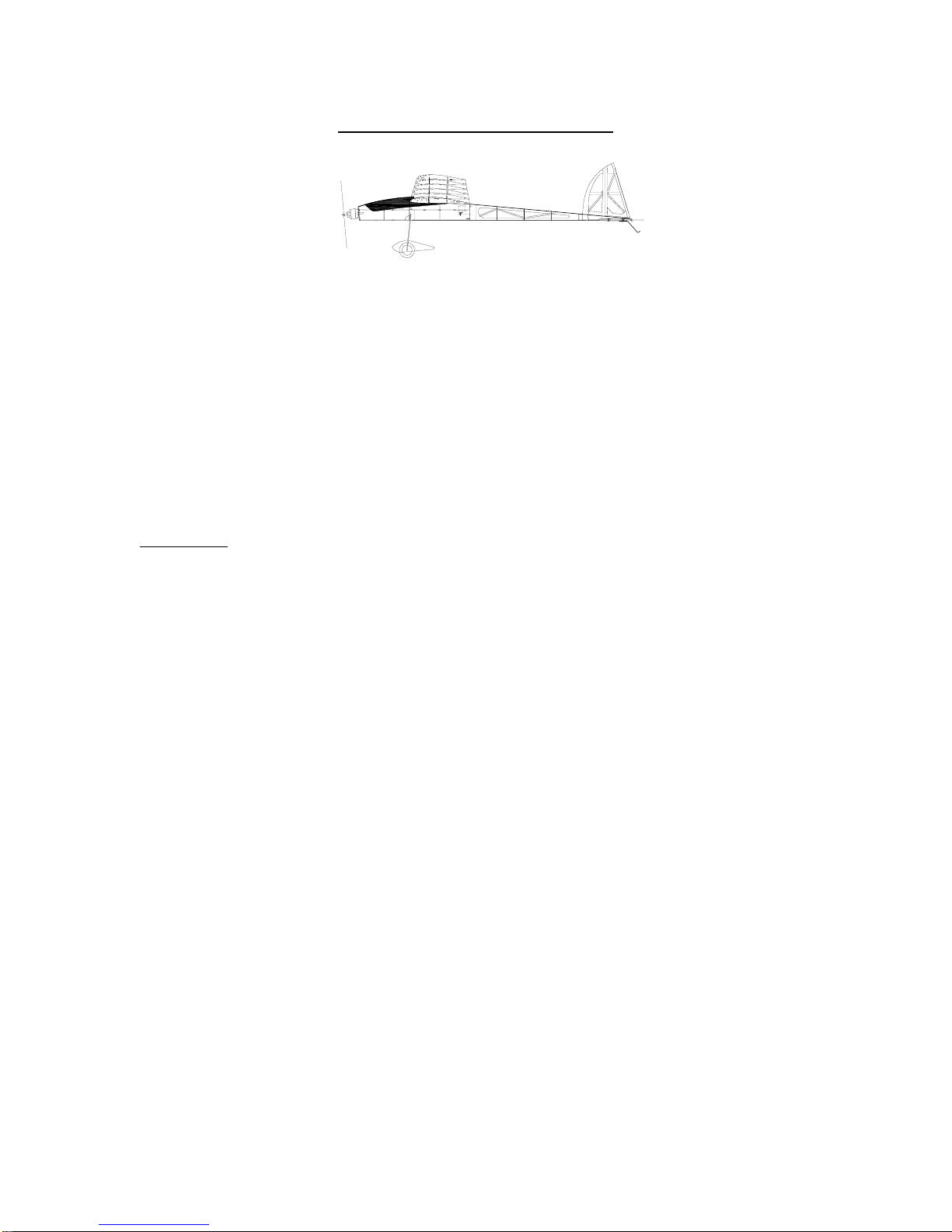
HeliumMG2
motorized glider / FPV platform
AA
BB
A
B
HS-65HB
DD
R10
R9
R11
R6
LE3
LE3
CC
C
C
CC
C
C
(He)MG2
Instruction Manual - Version 1.00b (02022010)
Span 77.75 in. / Length 44.5 in. / Area 645 Sq. In. / Weight 25 oz.
Made in the USA!
Of U.S. and Imported Parts

© 2008 Stevens AeroModel. Page 2 of 52
***Cautions***
1. Power system.
Overpowering this model with a heavier / more powerful system is not recommended.
Stevens AeroModel recommends a power system no greater than 300W, a maximum
pitch speed of 50 mph, and a maximum all up weight (AUW) of 36 oz.
Outrunner motors like the Hacker A30 transmit a great deal of stress to the motor
mount. DO NOT run your motor up until you have verified that your blade is accurately
balanced and in perfect track. Finally, disable your ESC’s prop braking function.
2. Throttle management.
Similar to full-scale and giant scale models this high performance model requires
careful throttle management. When tracking through a down-line it is mandatory to
govern the use of throttle, slowing the models descent, to avoid over speeding the
airframe.
WARRANTY
Stevens AeroModel guarantees this kit to be free from defects in both material and workmanship
at the date of purchase. This warranty does not cover any component parts damaged by use or
modification. In no case shall Stevens AeroModel’s liability exceed the original cost of the
purchased kit. Further, Stevens AeroModel reserves the right to change or modify this warranty
without notice.
LIABILITY RELEASE
In that Stevens AeroModel has no control over the final assembly or material used for final
assembly, no liability shall be assumed nor accepted for any damage resulting from the use by
the user of the final user-assembled product. By the act of using the user–assembled product,
the user accepts all resulting liability.
If the buyer is not prepared to accept the liability associated with the use of this product, the buyer
is advised to return this kit immediately in new and unused condition to the place of purchase.
THIS PRODUCT IS NOT INTENDED FOR CHILDREN 12 YEARS OF AGE OR YOUNGER
WARNING: This product may contain chemicals known to the State of California to cause cancer
and or birth defects or other reproductive harm.

© 2008 Stevens AeroModel. Page 3 of 52
REQUIRED TO COMPLETE KIT:
Kit Contents:
Laser Cut Wood (21 Sheets – See inventory on following pages)
Computer Drawn Plan Set
Illustrated Instruction Manual
Flat Stock and Push-Rods:
o4 - 1/4 in. x 24 in. Square Balsa Leading Edge
o1 - Pre-Bent Landing Gear (0.125 in.)
o2 - 48 in. length Flat Carbon Fiber Stock
o1 - DuBro Micro2 30in Pushrod System (DUB922)
o1 - Pair 2-1/4 in. foam wheels
Large Hardware Bag: (4x6 Bag):
o1 - Pair Delrin wing tip joiners
o1 - Package Rubber Bands #33
o1 - 4 in. length 1/16 in. aluminum tubing
o1 - 4 in. length 1/32 in. music wire
o3 - 3/16 in. x 3.75 in. Hardwood Dowels
Small Hardware (2x3 Bag):
o1 - 1 in. length 3/32 in. ID silicone fuel tubing
o2 - DuBro Micro2 Control Horns (1 pkg. / DUB919)
o2 - DuBro Mini EZ Connectors (1 pkg. / DUB845)
o2 - 1/8 in. star washers (wheel retainers)
o2 - 4-40 x 3/8 in. Nylon Machine Screw
o2 - 4-40 x 1-1/2 in. Nylon Machine Screw
o4 - 15/32 in. x 1/8 in. OD Aluminum Tubing (anti rotation pins)
o4 - 4-40 x 3/8 in. Machine Screw (motor mounting)
o4 - #2 x 1/4 in. Screw (A20-20L motor mounting)
o4 - assorted small black rubber bands
o8 - 4-40 Blind Nut
o10 - 3/16 in. Neo. Magnet
Recommended Finishing Items:
1. 2 Rolls of AeroFILM or AeroFILM Lite (Solarfilm, Solarfilm Solite, or Nelson Lite Film may be substituted).
Suggested Electronics:
1. 2 – High performance micro servos (Hitec HS-55 or HS-65)
2. 1 – Hitec HS-56 sub micro servo (for spoiler installation)
3. 1 – 6 in. servo extension (for spoiler installation)
4. 1 – Full range micro receiver (Castle Creations/Berg Micro Stamp 4 or 4L)
Power Systems:
1. Hacker A30-28S, E-Flite Park 480 1020kv, SA Sport 480 A2810-11
2. 9x5-10x5 APC-E Propeller. If you desire to utilize a folding propeller you will be required to reverse the motor
shaft of the Hacker and VSport motor - Out of the box the E-Flite motor is better prepared to accept a collet
style yoke and folding propeller assembly. We suggest using high quality Aeronaut Blades and an aluminum
yolk assembly. See www.stevensaero.com for suggested items for this model.
3. 11.1v 2100mAh LiPo (Rated for 15C discharge).
4. Castle Creations Thunderbird 36 or Phoenix 25 ESC – (Enable propeller braking)
Building Supplies Required:
1. Thin CA (super glue) and glue tips
2. Medium CA (super glue) and glue tips
3. Thread Locking Compound (Blue)
4. Hobby knife and blade(s) #11 and straight edge
5. Fine grit sand paper 250/400/600 and sanding block
6. Clear tape ¾” wide scotch or DuBro hinge tape.
7. Balsa wood filler
8. .047 in., 1/16 in., 1/8 in., and 3/16 in. drill bits.

© 2008 Stevens AeroModel. Page 4 of 52
Laser Cut Parts Inventory
Wing Parts
Balsa 1/16" A-HM
Balsa 1/16" AB-MH
Balsa 3/32" AB-MH
Balsa 1/16" ABC-MH
Balsa 1/16" AB-MH
Balsa 3/32" AB-MH
W6b
W6a
S2
S11
R7a
R8a
R9a
R10
R7
R8
R9
R6
W6
<- T5
<- T6
W6
R6
<- T6
<- T5
S11
S2
R6b
R10a
R7a R8a R9a
R6b
R10a
SW1
SW2
SW3
SW4
SW5
SW2
SW3
SW4
SW5
S9
S9
R1a
R1b
R3aR2a
R4b
R4a
R3b
R1a
R1b
R3a R2a
R4b
R4a
R3b
S1a
S1b
R2
R4
R3
R5
R2
R4
R3
R5
R2b
R2b
T4 ->
<- T4
S4
S6
S4
S6
F16
HEMG2 01/21
Fuselage Part
HEMG2 02/21
HEMG2 03/21
HEMG2 04/21
HEMG2 05/21
HEMG2 06/21
R10
R7
R8
R9

© 2008 Stevens AeroModel. Page 5 of 52
Wing Parts
Balsa 1/8" ABC-HM
Balsa 3/32" AB-MH
Balsa 3/32" AB-HM
Balsa 1/8" AB-MH
Balsa 1/8" ABC-HM
LE2
LE2
LE1
TE2
<- W5
R11
W7
W8
TE2
<- W5
R11
W7
W8
W8 W8
S5b
S3b
W4b
SP1
SP2
T2a
TE1a
TE1b
LE1
W4a
W3
W2
W6
W3
W3
W3
W6
W2
W2
W2
S5a
S3a
T3b
T2b
T3a
T1b
T1a
R1
DOWEL JIG01
W1b
R1
HEMG2 07/21
HEMG2 08/21
HEMG2 09/21
HEMG2 10/21
HEMG2 11/21
UNDERSIDE TRAILING EDGE BEVEL 45 DEG.

© 2008 Stevens AeroModel. Page 6 of 52
Fuselage Parts
Balsa 1/16" ABC-MH
Balsa 3/32" AB-MH
Balsa 3/32" AB-MH
Balsa 1/8" ABC-HM
Balsa 3/32" AB-MH
Balsa 3/32" AB-MH
F13
F13
C C
F15a
A
B
A
B
H1a
H1c
H2
F17
F15b
A
B
A
B
H1b
F10
F10
A
BFSb
F12a
F12c
A
BFSb
F12b
F14
C
C
C
C
C
C
C
C
F11b
F11a
H3
H3
HEMG2 12/21
HEMG2 13/21
HEMG2 14/21
HEMG2 15/21
HEMG2 16/21
HEMG2 17/21

© 2008 Stevens AeroModel. Page 7 of 52
Fuselage Parts
Ply 1/32"
Balsa 1/8" AB-HM
Ply 1/16"
LPly 1/8"
H4
F5 TOP F6 FORWARD/TOP F7 FORWARD/TOP F8 FORWARD/TOP F9 TOP
R6a
R5a
R5a
R6a
F1 TOP
F0 TOP
F3 TOP
F4 TOP
F2 TOP
D
D
D
G1
G1
G2
F19b
W1a
F19a
F19c
H1d
H3
F18
F18
LE3
S10
S10
S8
LE3
S8
SP3
SP3
W6c
SP4
HEMG2 18/21
HEMG2 19/21
HEMG2 20/21
HEMG2 21/21
© 2008 Stevens AeroModel. Page 8 of 52
General Assembly Instructions
AA
BB
A
B
HS-65HB
DD
R10
R9
R11
R6
Thank you, for purchasing this Stevens Aeromodel HeliumMG2 – “2-Meter Motorized Glider / FPV Platform”. This kit
provides the builder and pilot a refreshing change of pace from heavy “ARF” style plywood box airframe construction, and
blends stick and tissue design methods of the past with state of the art CAD technology and precision interlocking laser
cut parts. The result is something you will find truly exceptional to build and fly. Please keep in mind that this kit is
intended for a novice-intermediate builder and novice-intermediate pilot as a 3 channel motor glider/trainer. If you do not
meet these criteria it is recommended to seek help from a more experienced builder / pilot.
Best Regards,
Bill Stevens
Stevens AeroModel “Laser Engineered”
P.O. Box 15347
Colorado Springs, CO 80935
Assembly Tips
READ THE INSTRUCTIONS and the plan sheet prior to starting any work!
Tape plans to work table. Protect plans from glue spills using the poly tubing your kit was bagged in.
Join all parts with Thin CA unless otherwise specified.
DO NOT REMOVE THE PARTS FROM THE BALSA SHEETS UNTIL REQUIRED!
DO NOT FORCE THE FIT. When in doubt, double check your parts. Removal of material should not be
required. If you feel that you have a poor connection, check first to see that the part is not upside down.
Reference each piece against the plan sheet.
Making solid glue joints: Hold parts together on top of plan sheet using moderate pressure to fit parts. Wick
Thin CA into joint. There is no need to pin parts to work table as all pieces interlock and self - jig.

© 2008 Stevens AeroModel. Page 9 of 52
Tail Feathers
General Construction Notes: This kit features our proprietary Trus-Loc™ system as such typical “stick” type construction
has been replaced by precisely cut “stick” components that are keyed to fit in only one direction. The “knuckles” of the
truss are identified with an alpha-numeric use this to match adjoining truss components “A” to “A” and “B” to “B” etc. If a
part does not fit properly chances are very good that you have the wrong part or the part is in backwards. Under no
circumstances should you need to fill significant gaps or re shape the parts.
1. All of the parts to create the tail feathers are located on the 1/8 in. hard balsa sheets 17 and 18/21. Remove
parts from the sheet with a sharp #11 hobby blade. Assemble the parts on top of your plan set using the
drawings on the plan to reference part location and orientation. Frame up all tail feather components as
illustrated below.
CC
C
C
DD
CC
C
C
2. With the balsa tail feather framework complete refer to the plan sheet and install provided carbon fiber flat stock
where indicated using medium CA glue.
3. Round the leading edge of the stabilizers leaving then sand a 45 degree bevel to the leading edge of all control
surfaces (That’s Rudder and Elevator only) in preparation for tape hinges.

© 2008 Stevens AeroModel. Page 10 of 52
Fuselage
General Construction Notes: This fuselage utilizes an improved tab and notch construction method developed by Stevens
AeroModel. Each component precisely interlocks using unique tab and notch sizes to allow the parts to only fit in one
direction. Where parts orientation can be reversed or inverted parts are scribed with a reference such as “top” or “front”
for proper orientation. Throughout construction we suggest dry-fitting all components, and using minimal amounts of glue
at tab and notch locations only to hold parts together. By dry fitting the fuselage, each successive component will assist
with pulling the assembly square and straight.
1. Begin construction of the fuselage by completing the following sub assemblies: Build 3/32 in. balsa former F12
from parts F12a, F12b, and F12c (sheets 14 and 16/21). Build 1/16 in. balsa former F15 from parts F15a and
F15b (sheet 12/21). Build two each 3/32 in. balsa fuselage sides FS from parts FSa, FSb, and corresponding
truss parts (sheets 14, 15, and 16/21) when constructing fuselage sides use a straight edge to align part along
bottom edge, see illustration below the following diagram. Build 3/32 in. balsa former F11 from parts F11a and
F11b (sheet 13/21). Finally, build 3/32 in. balsa hatch component H1 from parts H1a, H1b, and H1c (sheet
13/21).
AA
BB
A
B
FSa
FSb
H1b
H1a
H1c
F12a
F12c
F12b
F15a
F15b
F11a
F11b
F12 F15
F11 H1
FS
2. Reference plan set for location of provided 4-40 blind nuts based on selected motor type then install to back
side of 1/8 in. lite plywood former F1 (sheet 21/21). The second photo in this series shows the F1 firewall with
blind nuts installed as viewed from the front. Secure blind nuts with gap filling medium CA glue. Set F1 aside.

© 2008 Stevens AeroModel. Page 11 of 52
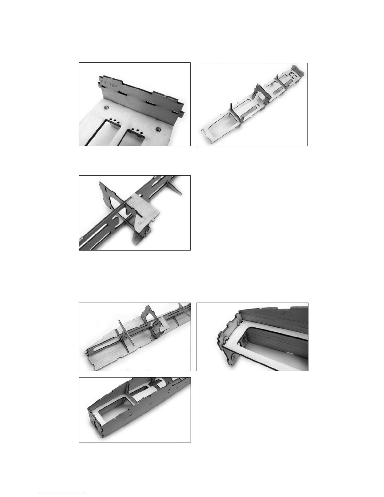
3. The 1/8 in. lite plywood central crutch F0 (sheet 21/21) is clearly marked “TOP” locate this part and invert so
that you are looking at the underside of the part. Install two 4-40 blind nuts to holes just aft of servo pockets as
illustrated below. Secure blind nuts with medium CA glue. Do not allow glue to come into contact with internal
threads of blind nuts. The second photo below shows the F0 central crutch with blind nuts installed as viewed
from the topside.
4. Install the 1/16 in. ply former F3 (sheet 20/21) by inserting it through the lightening hole central to the F0 central
crutch then aligning the notches in F3 with the crutch sides and gently twisting it into location. See illustration
below. Make certain that the etching on F3 faces forward and to the top-side of the crutch assembly.
5. The 1/8 in. lite plywood parts F2 and F4 (sheet 21/21) are installed to the central crutch as illustrated below.
Make certain that the etching on these parts faces forward and to the top side of the central crutch.
© 2008 Stevens AeroModel. Page 12 of 52
6. Locate the 1/16 in. ply former F5 (sheet 20/21) and dry fit to the central crutch as illustrated below. Again, pay
attention to proper top side and forward orientation.
7. 1/16 in. ply part G1 (sheet 20/21) key to center crutch assembly as illustrated below. Tack glue G1 to the F3
former to assist with retaining this part.
8. Key the completed central crutch assembly to one of the FS 3/32 in. fuselage sides and bond with thin CA glue
at tab and notch locations. Next install the F1 firewall to the fuselage assembly observing proper top and front
orientation and bond to assembly using thin CA glue. Complete step by joining the second FS fuselage side to
the opposite side of the central crutch. With full access to central crutch, fuselage sides, and F1 firewall now is
the best time to build up a solid glue fillet (use medium gap filling CA) where F1 meets the crutch and fuselage
sides.
© 2008 Stevens AeroModel. Page 13 of 52
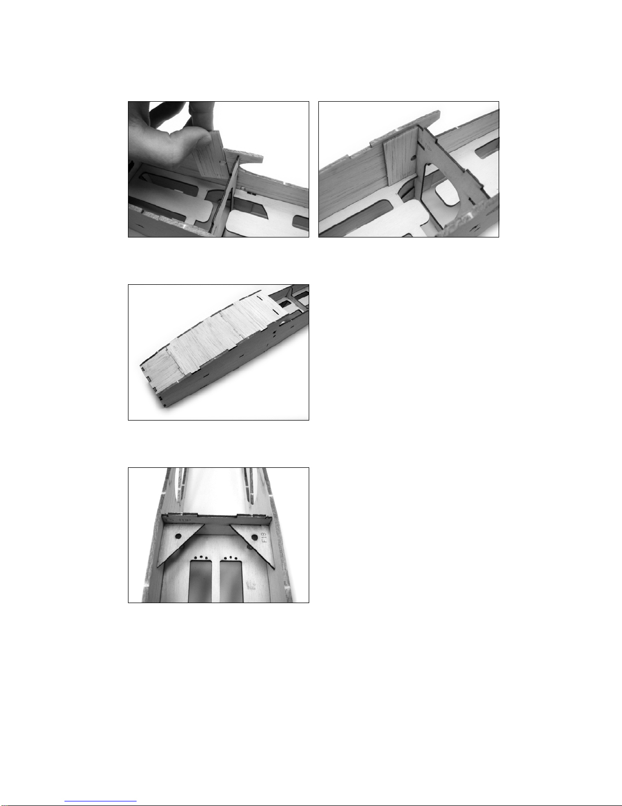
9. Install the 1/16 in. balsa forward cross-grain fuselage doubler F10 (sheet 12/21) as illustrated below. Match the
3/16 in. hole in F10 with that of the fuselage sides. Bond using medium CA glue.
10. Install 3/32 in. balsa part F12 (previously assembled in step 1) to top (curved) surface of fuselage assembly as
illustrated below. Retain by tack gluing with thin CA at tab and notch locations.
11. Install the 1/16 in. plywood F18 wing dowel guides/fuselage side braces (sheet 20/21) using the tab and notch
holes in F5 to align the parts. Retain with thin CA glue.
© 2008 Stevens AeroModel. Page 14 of 52
12. Install the 3/32 in. balsa former F11 (previously assembled in step 1)
13. Bond the 1/16 in. ply part G2 (sheet 20/21) into position directly aft of F15 as illustrated. Build up a solid glue
fillet between G2 and surrounding structure on inside of fuselage.
14. Locate the following parts: 1/16 in ply former F9 (20/21) and 1/16 in. balsa part F16 (sheet 2/21). Key F16 to
the back side of F9 using the notches in F9 to register the part. Now key the assembly to one of the fuselage
sides as illustrated below. Retain parts with thin CA glue. Do not glue the second fuselage side to the
assembly at this time.

© 2008 Stevens AeroModel. Page 15 of 52
15. Install two 4-40 blind nuts to one side of 1/8 in. balsa part F17 (sheet 17/22) then install F17 spanning aft end of
fuselage and former F16 as illustrated in the second photo below.
Finally pull the second fuselage side together with these assembled parts and tack bond with thin CA glue.
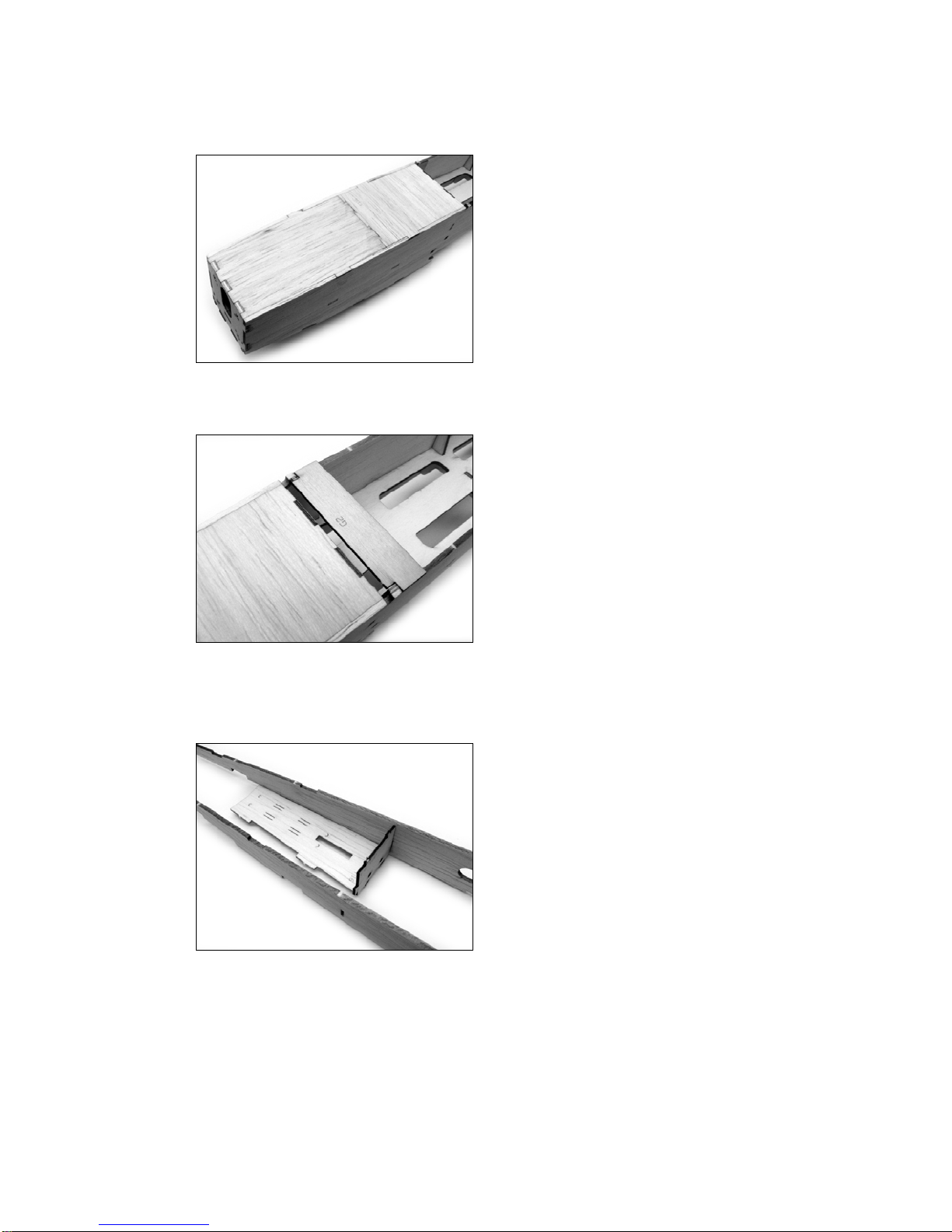
16. Install the 1/16 in. balsa part F14 (sheet 12/21) to the underside of the fuselage assembly. F14 extends from
F5 to laminate on top of F16. Tack glue this former to the fuselage at the tab and notch locations.

© 2008 Stevens AeroModel. Page 16 of 52
17. With the fuselage supported on your flat work table locate the 1/16 in ply parts F6, F7, and F8 (sheet 20/21).
These parts also have a top and forward designation etched on them. Pay careful attention to the part
orientation as you install and tack glue these to the fuselage assembly in their corresponding positions.
18. Install the 1/16 in. balsa aft cross grain doubler F13 (sheet 12/21) register part against the inside aft surface of
former F5 and F14 aligning the 3/16 in. hole in the doubler with the matching hole in the fuselage sides as
illustrated below. Bond part using medium CA glue.
19. Complete aft end of fuselage by installing 1/16 in. balsa part F15 (assembled in step 1) aligning tabs in former
with notches in fuselage. F15 spans former F5 to the tail of the fuselage assembly. Tack glue to retain part.

© 2008 Stevens AeroModel. Page 17 of 52
20. Final Glue Fuselage. Revisit all tack glued parts, hold the fuselage flat and square on your building board and
wick thin or medium CA glue along all part joints.
21. Complete the battery hatch catch assembly. Dry fit the 1/8 in. lite ply H3 (sheet 21/21) part as illustrated in the
first photo below. Now key the 1/16 in. balsa part H4 (sheet 20/21) to the fuselage on top of H3 and interlocking
with former F5 as illustrated in the second photo. Square both parts, as one unit, to the former and retain with
thin CA glue.
22. Locate the 3/32 in. balsa part H1 (assembled in step 1) on top of 3/32 in. balsa part H2 (sheet 13/21) matching.
Drive the tabs of the 3/32 in balsa part H3 (sheet 13/21) through stacked H1/H2 parts at notch locations. H3
properly locates H1 and H2. Bond hatch components together using medium CA glue.
Set the hatch assembly on top of your work table so that you are looking at the outside surface of the parts.
Bond the 1/32 in. ply part H1d to the exposed catch tab of the assembly as illustrated below.

© 2008 Stevens AeroModel. Page 18 of 52
23. Fill 3/16 in. diameter hole in battery hatch with a drop of medium CA glue then install one 3/16 in. diameter Neo.
Magnet to hole as illustrated below. Seat magnet only so that it is flush with the outside surface of the battery
hatch.
24. As magnets are polarized, attracting from one side and repelling when reversed, it is essential to identify the
proper polarity and install corresponding catch magnet without reversing it. Take a second Neo. Magnet and
allow it to “snap” itself to the previously installed catch magnet in the battery hatch. The magnet will
automatically flip to its attractive pole. Use a permanent marker to mark the outside surface of this magnet.
Remove the free magnet from the battery hatch and install within the fuselage catch assembly as illustrated with
the non-marked side exposed as illustrated below. Test the fit and function of your hatch. If satisfied that
you’ve correctly installed the second magnet to “attract” commit the part with CA glue.
25. Final Sand Fuselage. Using a sanding block or bar and fine grit sand paper lightly sand the fuselage and shape
as desired in preparation for covering with AeroFILM or AeroFILM Lite.

© 2008 Stevens AeroModel. Page 19 of 52
Landing Skid
1. From the DuBro RC pushrod kit (DUB922) cut a 4-1/2 in. length of the 0.045 in. diameter wire. Use the plan
set as a guide and bend this wire to the shape illustrated.
2. Locate the 1/16 in. ply part F19b (sheet 20/21) on top of 1/32 in. ply part F19a (sheet 19/21) matching the
corresponding edges and laser drilled holes in each part. Bond together using medium CA glue. Once glue
has cured test fit your bent tail skid wire to assembly and adjust fit if required. Bond tail skid wire within parts as
illustrated below using medium CA glue.
3. Bond the F19c 1/32 in. ply part (sheet 19/21) on top of F19b to capture wire tail skid. Allow glue to cure then
use the plan set once again as a reference an bend wire to final shape required by tail skid assembly. See
illustration below.

© 2008 Stevens AeroModel. Page 20 of 52
Pushrod Housing Installation
1. From the DuBro RC pushrod kit (DUB922) thread the plastic push rod housing through the fuselage assembly
as illustrated below. The pushrod housing passes through pre-cut holes in ply formers and exits fuselage
through one of the partially cut exits. Complete one side at a time using the plan set as a reference start
threading the housing from former F5 aft through fuselage. Housings will not cross so stick to the pre-drilled
holes in the formers on the same side as your start hole.
2. Once your housing has reached one of the pre-defined exit points through the balsa top or bottom of the
fuselage assembly remove the exit plug by completing the cuts in the top or bottom former to create an exit slot
as illustrated below.
3. With the exit point plug removed complete the pushrod installation by allowing the pushrod to extend
approximately 1/8 in. beyond the end of the exit point. Bond push rod housing at each capture point using CA
glue then trim excess housing to extend only 3/16 in. forward of former F5 as illustrated below.
Table of contents


