moyes Malibu User manual

Moyes Delta Gliders Pty. Ltd.
Version 3.00
Malibu
Owner’s manual

MALIBU OWNERS MANUAL
Version 3.00 3
CONTENTS
Amendments......................................................................................... 4!
Document format .................................................................................. 4!
Introduction ........................................................................................... 5!
What is the Malibu like to fly? ............................................................... 6!
Assembly from short pack to full length ................................................ 7!
Set up procedure .................................................................................. 9!
Pre-flight check ................................................................................... 13!
Flying the Malibu................................................................................. 15!
Pack up............................................................................................... 16!
Specifications...................................................................................... 18!
Design notes....................................................................................... 19!
Operating limitations ........................................................................... 19!
Disclaimer ........................................................................................... 20!
General tuning hints............................................................................ 21!
Maintenance schedule........................................................................ 25!
Checking the stability system.............................................................. 26!
Spare parts ordering ........................................................................... 27!
Bolt index & list ................................................................................... 28!
Purchase record.................................................................................. 33!
Maintenance log.................................................................................. 33!
Instructional video list.......................................................................... 34!

MALIBU OWNERS MANUAL
4Version 3.0
AMENDMENTS
DOCUMENT FORMAT
This document is formatted for double sided printing, the odd numbered pages have a
wider margin on the left and the even number pages have it on the right. That allows for
binding along the edge.
Version
Date
Changes
1.00
23 March 2010
Initial release
2.00
8 April 2010
Include Malibu 166 specs
3.00
27 August 2021
Update M2188

MALIBU OWNERS MANUAL
Version 3.00 5
Moyes Delta Gliders Pty. Ltd.
Unit 4/5 Clerke Place, Kurnell NSW 2231 Australia T: +61 (0)2 9668 8686 E: moyes@moyes.com.au
INTRODUCTION
Thank you for choosing your Moyes Malibu. This glider epitomises all the qualities of
safety, performance and handling that is the Moyes tradition. The development of the
Malibu is indicative of the dedication of the Moyes design team who strive to offer a
range of high quality hang gliders for all pilots.
This glider is intended for beginners and experienced pilots; beginners who need a safe
and steady glider; experienced pilots seeking something for the sand dunes or a glider
that can catch the smallest of thermal bubbles.
Please read this manual thoroughly, familiarise yourself with the set-up and pack up
procedures and take the time to practice these before going out to your site.
If in doubt about any aspect of operating your Malibu, consult your manual or seek
advice from your Moyes dealer. Moyes are happy to help with advice and hints.
Since 1967, Moyes Delta Gliders have been on the cutting edge of hang glider
development. A family owned business operating under homespun values, we provide a
comprehensive international network to service all pilots. We work with some of the best
pilots in the world to ensure that our gliders are built to the highest standards and
stringently tested in order to improve their performance, handling and safety.
We wish you the very best flying,
The Moyes Team
MALIBU OWNERS MANUAL
6Version 3.0
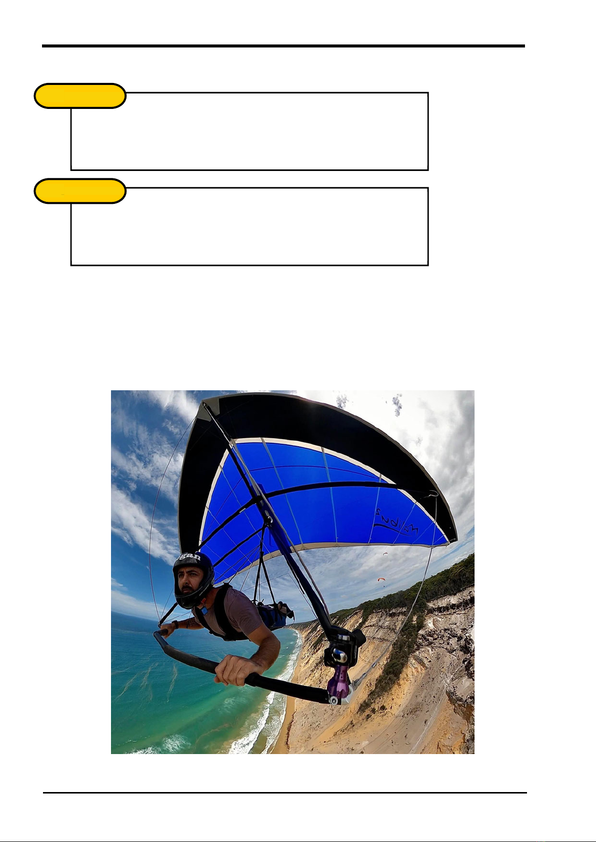
WHAT ISTHE MALIBU LIKE TOFLY?
From the moment you launch you can feel the Malibu is a calm steady glider and easy to
control.
If you are a novice, the low speed capability and steadiness of this glider are keys to
developing confidence and with confidence, skills will follow. Use the Malibu to grow
your skills in all areas; launching, landing, thermaling and dune flying. Most of all it is the
easiest way to experience the joy of flight.
For pilots with more experience, this glider is a hoot to fly on sand dunes or to take
thermaling. Because the Malibu can fly so slowly and in tight banked turns, you can core
very small thermal bubbles and it is so easy to do. Make sure to use this characteristic to
your advantage. Performance gliders cannot do it and don’t be surprised if you find
yourself circling more tightly than a gaggle of paragliders.
With sand dune flying, this glider lets you extract the last bit of lift from the dunes. The
glider handles very well at low speed and you’ll often find that when you think you are
down you can nudge the bar out and there is a little more height to be gained.
When you need to make low and tight turns to stay in a narrow lift band, the Malibu
keeps its nose up and the inner tip stays afloat. But please don’t overdo it, gravity cannot
be ignored.
The stall is mild and progresses slowly. When it starts you can hear the sail ruffle but the
glider continues to fly and handle. Push it a bit more and it begins to mush and settle
without dropping a wingtip.
The glider has good energy retention for this style of glider. You can use this
characteristic to zoom along the beach and pass through patches of nil lift then use the
speed to climb onto the dune at the other side.
If you are reading this from the memory stick, you can view a short video to show the
Malibu in flight.
Click the logo to view the video.
On glider video; click the logo.
MALIBU OWNERS MANUAL
Version 3.00 7
ASSEMBLY FROM SHORT PACK TOFULL LENGTH
You may have received your glider “short packed”. This is when the outer leading edges
have been removed and packed in with the rest of the glider so the packed length is
shorter. Normally your Malibu will have been assembled to full length by your dealer. If
your glider is already full length, skip this section and go to the Set-Up Procedures
section.
All references to “top”, “bottom”, “left” and “right” are referred to in flying mode.
If you are reading this from the memory stick, you can view an instructional video on
assembling from short pack. Click the logo to view the video.
1. Unzip the glider bag and roll the glider so that the top is
up. Undo the straps and extend the sail.
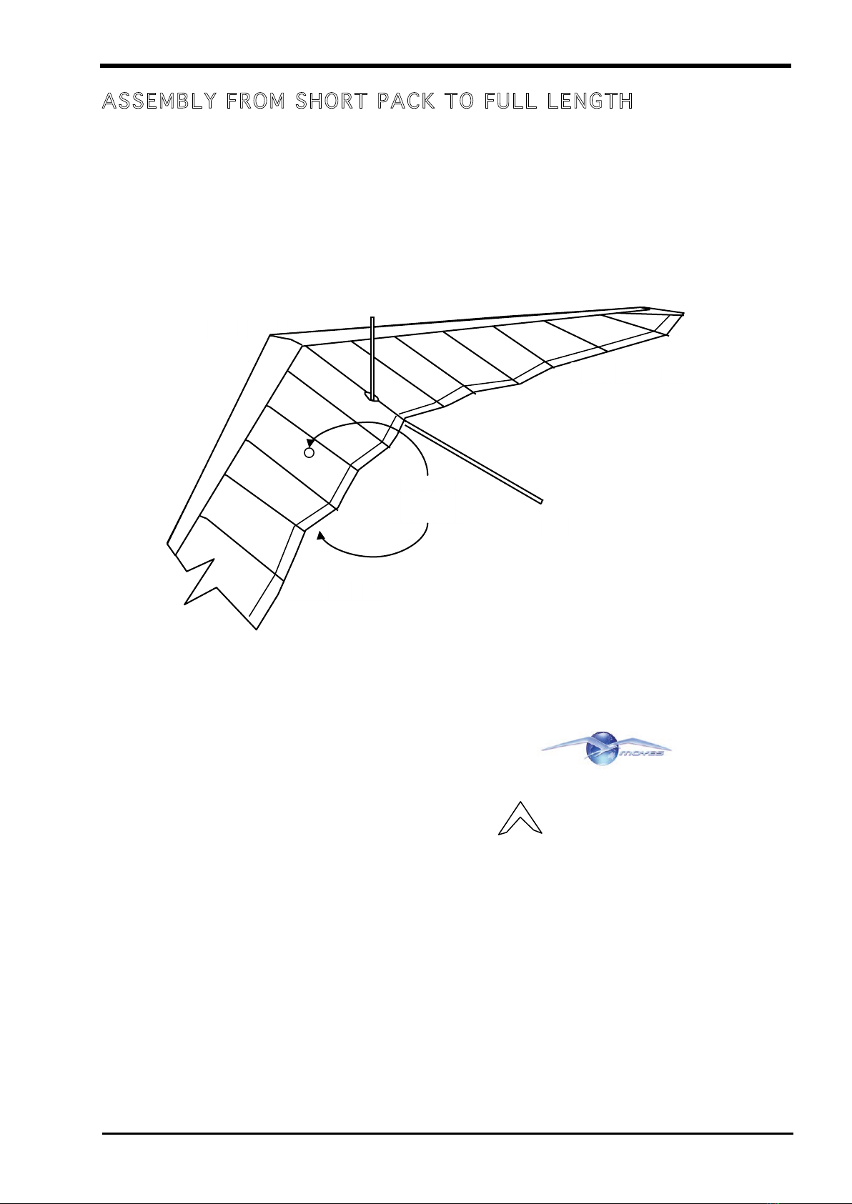
2. Open the wings about 40 degrees
3. The rear leading edge tubes will be packed in the box with the glider. Locate
them and remove the packaging.
4. On the glider, inside the leading edge pocket, remove the packaging from the
end of the front leading edges.
5. On the rear leading edge tubes, identify the right and left sides by laying the
leading edge on the ground in the approximate place along the wing where it will
go. Fit the dive strut in its socket. The dive strut should be at the rear and
pointing towards the keel. Now note the position of the plastic grey hook on the
leading edge, it should be towards the bottom of the tube. If not, that leading
edge belongs on the other side.
Right
Left
Front
Rear
Top surface
Under surface
MALIBU OWNERS MANUAL
8Version 3.0
6. On the rear leading edge tubes, note the slot at the inner end. This slot locates
the leading edge onto the locating pin when it fits into the front leading edge tube.
7. Take the rear leading edge for the right side and slide it inside the sail at the right
wing tip. As you proceed, hold the dive strut against the leading edge so that it
can slide in too and then make sure that the dive strut exits the sail via the small
hole in under surface of the sail.
8. Move to the leading edge where the front and rear leading edges meet and open
the inspection zip. Align the rear leading edge so that it slides inside the front
leading edge. Rotate the rear leading edge until the slot (previously noted)
locates into the locating pin that is in the front leading edge. Do NOT remove the
locating pin, there is no need.
9. At the wing tip, check that the dive strut is exiting the sail correctly. If not, you
may need to rotate the outer leading edge 180 degrees. Do this by sliding it
partially out of the front leading edge so that it is free of the locating pin on the
front leading edge.
10. At the wing tip, the sail is held in place by a strap that fits over the end of the
leading edge. There is also a Velcro band that goes around the leading edge
after the strap is fitted. To fit the strap, put your left hand inside the sail and grip
the leading edge. With your right hand pull the sail strap over the leading edge.
There is an extra loop on the sail tip that you put your fingers in to pull the sail.
Fasten the Velcro band around the leading edge tube; the Velcro may get hidden
between the leading edge tube and the sail and you will need to pull it out with
your fingers.
Tip 1: Before fitting the strap, put the Velcro band around the tube and just attach
the very tips. This stops it getting caught behind the tube.
Tip 2: If the strap is hard to fit, try spreading the wings a little more or less if you
having difficulty.
11. Repeat steps 7 to 10 for the left wing.
Verify that the straps are on the right way up. It’s possible to have them 180
degrees out.
CHECK
!
MALIBU OWNERS MANUAL
Version 3.00 9
SET UPPROCEDURE
There are two set up methods and both are covered in this procedure.
•Standing on the control frame.
Good for lighter winds. The glider stands on the control frame and then you
open the wings and finish assembly. The glider stands rear to wind.
Click on the logo for an instructional video.
•Flat on the ground.
Good for stronger winds. The glider is assembled flat on the ground with the
nose into wind.
Click on the logo for an instructional video.
Choose the method you want and follow the steps below. Differences for each method
will be described in the procedure.
1. Place the glider (still in the bag) on the ground with the nose into the wind and
the zipper up. Undo the zipper.
2. Undo the ties that hold the control frame; remove padding and spread the
uprights (downtubes).
3. The glider is fitted with a speed bar which has a top and bottom. When in flying
mode the middle bend in the speed bar is forward and is angled downwards
slightly. Connect it to the corner brackets with the AN4 bolt and Pip Pin.
4. Remove the batten bundle and any padding.
5. For standing set up, rest the glider standing on the control frame. Attach the
nose wire. Move the glider so it is at right angles or slightly rear facing to the
breeze. The glider may flop to one side of the control frame. This is normal.
For flat set up, flip the glider over with the control frame folded back. The glider
should be nose into the wind. Make sure the nose is flat on the ground; this will
avoid the breeze lifting and flipping the glider when the wings are spread.
Check that all wires are outside the control bar.
CHECK
!
Check that the Pip Pin is all the way through and secure.
CHECK
!
MALIBU OWNERS MANUAL
10 Version 3.0
6. Remove the glider bag. For standing set up, take it from the nose first to avoid
the bag pulling the glider over should it be caught by a fiendish gust. Remove
remaining ties and padding,
7. Move to the nose of the glider and insert the nose batten checking that it fits over
the lug on the keel. After initial assembly you can leave the nose batten in but
pull it out slightly when packing up.
8. Spread the wings, taking care that any wires are not snagged around the keel or
fittings. Do not force the wings open if they are stuck, check for snags.
9. Erect the king post and attach the rear luff line wires to the top of the king post by
clipping the small snap hook clip through the thimble.
10. Move to the rear of the glider. At the keel, pull back the double wire crossbar
restrainer cable so the stainless steel shackle will clip into the catch (Bailey
Block) at the rear of the keel.
11. Take the rear top wire, feed it through the restraining loop on the back of the sail
and clip the ring into the catch. The top wire can feel quite tight. Try pulling the
ring end of the wire upwards with a little force and then put it down into the clip. If
that does not work, unclip the nose wires, attach the rear top wire then re-attach
the nose wires.
12. Take the battens from their bag and lay the green-tipped battens behind the right
wing, starting with the keel (longest) batten, out to #7 near the wing tip. Take the
red (left) battens and match them against their appropriate green partner and
check for symmetry. If any inconsistencies occur, the full set of battens should
be checked against the template and corrected. (Refer to General Tuning
section.)
Check that your glider is in no danger of being blown over.
CHECK
!
Check that the bridle lines are not twisted or kinked.
CHECK
!
Check that the rear top wire is free of any of the luff lines.
Check that the rear wire is through the restraining loop on the sail.
CHECK
!
MALIBU OWNERS MANUAL
Version 3.00 11
13. Familiarise yourself with the functioning of the batten flip tips. Do not use force to
release them as that will break the clasp. To release them, squeeze the tip and
lift. The batten length is adjusted by screwing the tips in and out. The length has
been adjusted at the factory and should be correct.
14. Starting at the centre of the glider, insert all the battens except the last one at the
tip. Gently push them into their batten pockets and secure them by opening the
batten tip, fitting it under the sail edging and closing the tip. Do not force the
battens.
15. The tip (#7) batten can now be installed. It should be installed so that the bend is
downwards. These battens locate onto the hook found on the back side of the
leading edge about 45 centimetres (18 inches) inboard from the tip. Sight through
the sail at the wingtip to ensure that the end of the batten is engaged on the hook
and secure with the double cord. The cord maybe quite tight. There is a loop on
the end of the cord to put for your finger through. Use it to pull the cord over the
batten tip.
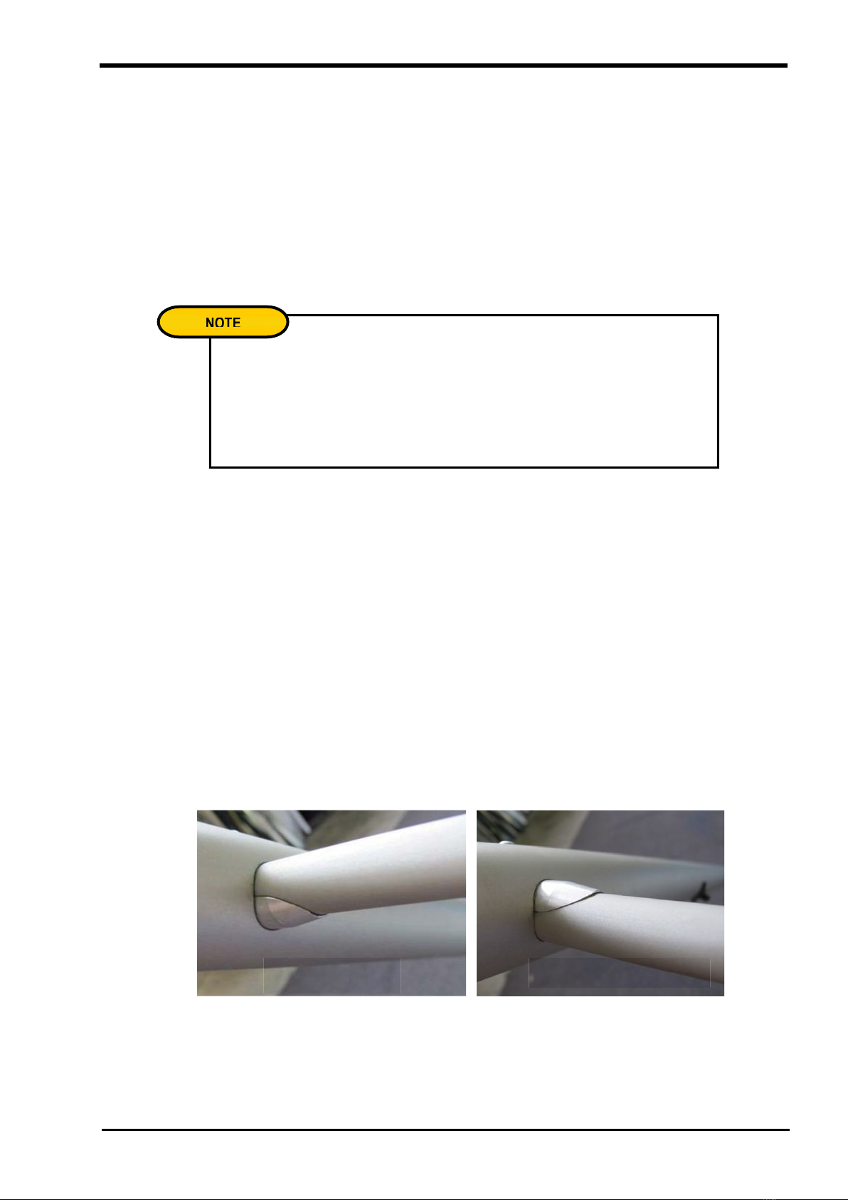
16. Insert the dive strut into the leading edge. The hole in the leading edge is oval
shaped to accommodate the mound on the dive strut. For thermaling, put the
mound at the bottom, this raises the dive strut for additional dive recovery. For
dune flying put the mound at the top to allow more sail movement during big
control inputs.
17. Fit the nose fairing by matching Velcro strips on the under surface. The top is
permanently attached via bungee cord.
If the battens fail to slide in completely, first check if it is the correct batten for
the pocket. It is most likely that the batten has stopped against the back of the
leading edge and requires lifting over to the front. To do this either flick the sail
up and gently push the batten at the same time, or walk to the front and lift the
sail forward bringing the batten tips over the leading edge.
NOTE
!
Thermaling / rough air
Sand dunes / smooth air
MALIBU OWNERS MANUAL
12 Version 3.0
18. For flat set up, if there is wind, get an assistant. Have your assistant lift the keel
while you lift the nose of the glider. Keep the angle of attack low so the wings do
not get lifted. Raise the glider up onto the control frame and attach the front wires
to the nose clip. From here on you will need your assistant to hold the nose while
you prepare the harness and perform pre-flight checks.
19. Check that the hang loop and back-up loop are in the correct position. The
shorter loop (main) should be towards the rear. The longer loop (back-up loop)
should be to the front. Check that the hang loops pass through the small
restraining strap which stops them sliding forward on the keel.
20. Clip your harness carabineer into both the main and backup loops. There should
be no tension on the backup loop when the harness is in the flying position.
Ensure that the carabineer is closed and the hang loops are hanging straight
from the keel.
Harness Adjustment
It is best to have your hang loops and harness adjusted as low as possible within the
control frame (2 – 7 cm above the base bar). This lower position gives maximum
stability and allows greater control input. It also gives better glider feedback.
If you need to raise or lower your harness, change your hang loops. Do not tie knots in
them. Your Moyes dealer can supply different length hang loops.
Check that hang loops are not damaged.
CHECK
!
When lifting the nose in a significant breeze, there is a high risk that the wings
could fold upwards before you can get the glider raised onto the control frame.
Avoid this by having an assistant lift the keel while you lift the nose keeping the
angle of attack down so that the wings do not fly up.
WARNING
WARNING
!

MALIBU OWNERS MANUAL
Version 3.00 13
PRE-FLIGHT CHECK
Follow the same routine every time you set up. If you are distracted, begin again. A
good habit is to touch or point to each component that you are checking. This ensures
that the check is more than just a cursory glance.
Starting from the hang loops and harness:
Control frame:
- all nuts & bolts are secure
- thread shows beyond the head of Nyloc nuts.
- speed bar is angled correctly (downwards)
- uprights straight.
King post:
- base bolts are secure.
Crossbar:
- ball is centred in socket joints
- no bends or dents
- side wire connects not twisted
Keel:
- sight for dents or bends
- pullback cable is not twisted
Nose plates:
- nose plates straight
- nuts and bolts done
- wires, thimbles and tangs straight
- Nose wire attached.
Leading edges:
- sight along leading edge for bends.
- feel along wings for dents in tube
- side wire connection, tangs, thimbles bolts.
Wing tips:
- tip batten is located on hook
- sail straps over tip and right way up
- dive struts fully inserted, raised lump at the bottom for thermaling
Battens:
- all battens tips done up.
Rear pullback:
- restraining cable shackle is secured in the Bailey Block
- top rear wire is through the loop on the sail rear.
- top rear wire is connected to Bailey block
- bottom rigging has no twisted tangs
King post:
- top rigging and luff lines free from twists.
Next wing:
- continue around the glider performing same checks on other wing.
Rigging:
- look out for frayed or corroded rigging, especially near swages.
Hang loops:
- no cuts or frays
- correct CG position
- harness attached, carabiner done up and in correct loops.
MALIBU OWNERS MANUAL
14 Version 3.0
The glider is now ready to fly!
Climb into the harness making sure your legs are through the leg loops. Check harness
height, helmet, instruments, wind at launch and broader conditions.
Never detach the harness from the glider until you are packing up. Climb into
your harness AFTER it is attached to the glider. This will avoid the risk of taking
off without being attached.
NOTE
!
Be mindful all rigging should be replaced according to the manufacturing
recommendation. There is a small label on the bottom rigging identifying the
date the wire was produced.
NOTE
!

MALIBU OWNERS MANUAL
Version 3.00 15
FLYING THE MALIBU
Ground Handling and Launching
The Malibu’s launch characteristics are mellow and predictable. The glider will lift at low
air speeds.
For ground handling in winds over 14 knots, you may find it difficult to keep the nose
down due to the pitch up created by the luff lines. For this situation try holding the base
bar instead of the conventional launch method of arms down the uprights.
In Flight
The glider is trimmed to fly a little faster than stall speed so you should not need to apply
much pitch input. Due to the nature of single surface gliders, the glide angle drops off
significantly at high air speeds. The best glide between thermals will be at lower speeds
(38kph 24mph). Take care in stronger winds to be within glide angle of a landing area. If
you find yourself “cornered” by a strong wind, look for landings downwind or wait
patiently for extra lift or for the wind to drop.
For small thermals, the glider can turn in very tight circles if it suits you. The inside tip
does not drop in and the glider does not spin.
Landing the Malibu
The success of any landing is linked to the accuracy and planning of its approach. Leave
ample time to plan and set up a safe landing with room for variable conditions or
misjudgement.
For this style of glider (single surface), fly fast to spoil your glide angle. To maintain your
glide angle fly slower (this works well for single surface gliders like the Malibu but may
not for high performance gliders).
While there is still enough airspeed left to flare, slowly increase your rate of push out
bringing it to a full UP and OUT arm extension. If the glider is gusted up or you have too
much airspeed, stop pushing (but do not pull in) until that energy has been used, then
complete the flare. Never swing your legs forward in anticipation of landing as this can
lead to a nose-in.
MALIBU OWNERS MANUAL
16 Version 3.0
PACK UP
Two methods of packing up the glider are described below;
•Standing on the control frame.
Good for lighter winds. The glider stands on the control frame and you fold the
wings in and finish packing. The glider stands rear to wind.
Click on the logo for an instructional video.
•Flat on the ground.
Good for stronger winds. The glider is packed flat on the ground with the nose
into wind.
Click on the logo for an instructional video.
Laying the Glider Flat
If the wind is over 16 kph (10 mph) and you wish to park the glider safely, it is best to lay
the glider flat on the ground with the nose into the wind. To do this, lift the nose fairing to
expose the nose catch assembly. Whilst holding the keel so the glider can’t blow over,
remove the nose wire ring from the Bailey Block and carefully walk forward with the nose
of the glider allowing the control bar to fold back under the glider until you have lowered
the wing to the ground.
If the glider is to be parked for any length of time, or if the wind is quite fresh, it is also
advisable to unclip the luff lines to prevent the nose from being lifted by the wind. From
here the glider can be quickly reassembled or broken down.
Packing up
This covers flat and standing pack up.
1. Standing pack up: turn the wings so that the wind is blowing on to the back of the
glider.
Flat pack up: Leave glider in the “flat” position described above with the nose into
wind.
2. At the wing tips, pull out the dive struts. Fold the dive struts in and attach them to
the Velcro patch under the leading edge.
3. Starting at the wing tips, remove all the battens. Be careful opening the batten flip
tips; no force is required other than squeezing. Do not force them open or the
clasp will break.
4. Gather the batten curved ends together and feed them into the bag in a bundle.
5. At the nose, detach the nose cover Velcro from the under surface. Place nose
cover on top of glider.
6. The nose batten stays in the glider. Lift it off its lug and let it sit over the front of
the nose plate.

MALIBU OWNERS MANUAL
Version 3.00 17
7. At the rear of the glider, unclip the crossbar pullback and kingpost wire.
8. At the rear of the glider and at the middle of one wing, lift the trailing edge of the
sail so that the leading edge folds in about half way. Do the same on the other
wing. Do not lift the leading edges too high when swinging them in. Repeat the
process to bring the leading edges right in against the keel.
9. If any sail is trapped between the keel and leading edge, pull it out from the top
and lay it out to the sides. Roll the sail until it lays against the leading edges. Roll
loosely; tight rolls tend to encourage wrinkles.
10. At the wing tips, fit the tip bags over the rolled sail.
11. From the rear of the glider unclip the luff lines and lay the kingpost forward.
Attach the luff line clip to the reinforced sail area around the king post base. Tuck
the luff lines into the sail.
12. At the rear of the glider, slide the padded sleeve up the keel until it covers the
tangs and fittings at the rear of the keel. Place a tie under the glider (around the
middle) and fasten the tie but leave it reasonably loose. Repeat with three more
sail ties, tidying the rolled sail as you go.
13. Place the cover bag over the glider.
14. Standing pack up: Unclip the front wires.
15. Carefully flip the glider onto its back.
16. Place the batten bag at the nose of the glider with the curves to the front. Put the
glider ties over the battens to hold the battens in place.
17. On the base bar, detach the corner bolt and fold the uprights down along the
keel; you may need to undo some ties. Fold the base bar down towards the rear.
Put the bolt back in the upright and do it up well so that it doesn’t come off during
transport. Bring all the wires forward to make a neat bundle, avoid kinks.
Refasten ties. Place padding around the bottom of the uprights.
18. Zip up the bag.
MALIBU OWNERS MANUAL
18 Version 3.0
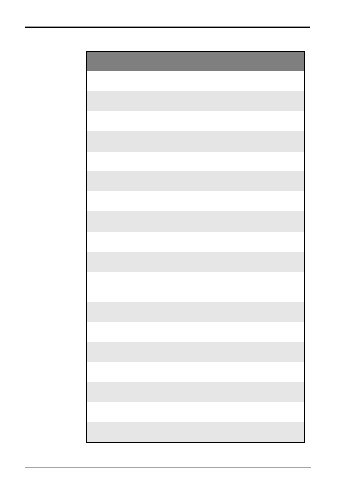
SPECIFICATIONS
Malibu 166
Malibu 188
Area
15.4 sq m
166 sq ft
17.5 sq m
188 sq ft
Span
9.2 m
30 ft
10.1 m
33.1 ft
Nose Angle
120.5 degrees
120.5 degrees
Aspect Ratio
5.5
5.8
Glider Weight
23 kgs
51 lbs
26 kgs
57 lbs
Optimum Pilot Weight
60 kgs
132 lbs
85 kgs
187 lbs
Hook-In-Weight
72-92 kgs
159-203 lbs
73-110 kgs
161-243 lbs
Packed-Length
5310 mm
17.4 ft
5950 mm
19.5 ft
Short-Packed Length
3510 mm
11.5 ft
4000 mm
13.1 ft
C of G from Front of Keel
1658 mm
65.3 inches
1750 mm
68.9 inches
Number of Battens:
Top
Bottom
15
0
15
0
VNE (Velocity Never Exceed)
85 kph
53 mph
74 kph
46 mph
VA (Design manoeuvring speed)
55 kph
34 mph
55 kph
34 mph
Trim Speed
32kph
20mph
32kph
20mph
Stall Speed
22kph
14mph
22kph
14mph
Max Speed
70 kph
43 mph
65 kph
40 mph
Best Glide Speed
38 kph
24 mph
38 kph
24 mph
Best Glide Angle
9.5:1
9.5:1

MALIBU OWNERS MANUAL
Version 3.00 19
DESIGN NOTES
This glider meets the Moyes standard for safety and performance.
Pitch stability and dive recovery come from the sail twist and the combination of the luff
lines and the dive struts. It is important to understand that any alteration to luff line
lengths or batten profile may reduce the glider’s pitch stability.
The Malibu meets or exceeds all DHV airworthiness standards. DHV is a German
standard broadly accepted in Europe.
OPERATING LIMITATIONS
The glider has been tested to these limits
•with a positive 30° angle of attack at 100 kph (65 mph);
•with a negative 30° angle of attack at 74 kph (46 mph);
•with a negative 150° angle of attack at 51kph (32 mph);
•Pitching moment tests at 32, 56 and 80 kph (20, 35 and 50 mph) to display the
gliders inherent positive pitch stability.
The Malibu has been designed for foot-launched gliding or soaring flight with the
following limitations:
The glider must not:
•be flown by more than one person;
•exceed 30 degrees nose up or down to the horizon;
•exceed 60 degrees bank angle to the horizon;
•be flown in excess of V.N.E. of 74 kph (46 mph);
•be flown inverted or backwards;
•be flown with auxiliary power without the approval of Moyes Delta Gliders
Pty Ltd.
Adhere to the recommended pilot clip-in weights as detailed in the specification.
Indicated stall speed is approximately 27 kph (17 mph) at maximum loading.
Indicated maximum speed is approximately 56 kph (35 mph) at minimum loading.

MALIBU OWNERS MANUAL
20 Version 3.0
DISCLAIMER
The owner and operator must understand that due to the inherent risk involved in flying
such a unique vehicle, no warranty is made or implied of any kind against accidents,
bodily injury or death. Operations such as aerobatic manoeuvres or erratic pilot
technique may ultimately produce equipment failure and are specifically excluded from
the warranty.
This glider is not covered by product liability insurance, nor has it been designed,
manufactured or tested to any state or federal government airworthiness standards or
regulations.
This manual suits for next models
2
Table of contents
Other moyes Aircraft manuals


