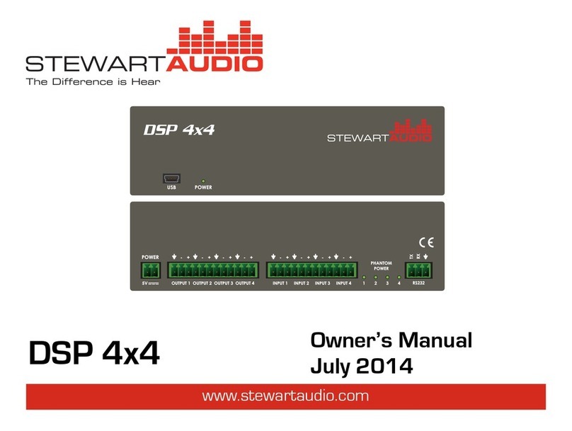
Stewart Audio DSP 4x4 User manual

DSP 4x4 Operations Manual Rev E Page 1
Table of Contents Top
DSP 4x4 Operation Manual
1 Important safety instructions
1. Please read carefully prior to product installation or operation.
2. Read these instructions.
3. Keep these instructions.
4. Heed all warnings.
5. Follow all instructions.
6. Do not use this apparatus near water.
7. Clean only with dry cloth.
8. Do not block any ventilation openings. Install in accordance with manufacturer’s instructions.
9. Do not install near any heat sources such as radiators, heat registers, stoves, or other
apparatus (including amplifiers) that produce heat.
10. The unit should only be connected to 120-240VAC, 50-60 Hz power supply. Use only the
power adapter that is sold with the unit.
11. Protect the power cord from being walked on or pinched particularly at plugs, convenience
receptacles, and the point they exit from the apparatus.
12. Only use attachments/accessories specified by the manufacturer.
13. Unplug this apparatus during lightning storms or when unused for long periods of time.
14. Refer all servicing to qualified service personnel. Servicing is required when the apparatus has
been damaged in any way, such as power-supply cord or plug is damaged, liquid has been
spilled or objects have fallen into the apparatus, the apparatus has been exposed to rain or
moisture, does not operate properly, or has been dropped.

DSP 4x4 Operations Manual Rev E Page 2
Table of Contents Top
2 Approvals
This equipment has been tested and found to be compliant with the limits for Class A Digital device
pursuant to part 15 of the FCC rules, and in compliance with the EN55022 and EN55024 EMC
standards.
3 Warnings
3.1 Explanation of Warning Symbols
3.1.1 Lightning Bolt
The lightning bolt within arrowhead symbol, within an equilateral triangle, is intended to alert the user to
the presence of un-insulated “dangerous voltage” within the product’s enclosure that may be of sufficient
magnitude to constitute a risk of electrical shock to person.
3.1.2 Exclamation Point
The exclamation point within an equilateral triangle is intended to alert the user to the presence of
important operating and maintenance (servicing) instruction in the literature accompanying the appliance.
3.2 Warnings
WARNING: TO REDUCE THE RISK OF ELECTRICAL SHOCK, DO NOT EXPOSE THIS PRODUCT TO
RAIN OR MOISTURE. DANGEROUS HIGH VOLTAGES ARE PRESENT INSIDE THE ENCLOSURE. DO
NOT OPEN THE CABINET. REFER SERVICING TO QUALIFIED PERSONNEL ONLY.
3.3 User Responsibility
3.3.1 Radio Interference
This product has been tested and complies with the EMC directive, and with FCC part 15 Class A. If
this product is not used in accordance with these operating instructions, it may cause interference
with to other equipment, such as radio and television receivers.
3.3.2 Maintenance
Clean regularly with a soft cloth to remove dust and debris. Also check that vent holes and slots
are not covered and that there is adequate ventilation for convection cooling.

DSP 4x4 Operations Manual Rev E Page 3
Table of Contents Top
4 Table of Contents
1 Important safety instructions.....................................................................................................................1
2 Approvals....................................................................................................................................................2
3 Warnings.....................................................................................................................................................2
3.1 Explanation of Warning Symbols.................................................................................................. 2
3.1.1 Lightning Bolt........................................................................................................................ 2
3.1.2 Exclamation Point................................................................................................................. 2
3.2 Warnings....................................................................................................................................... 2
3.3 User Responsibility ....................................................................................................................... 2
3.3.1 Radio Interference................................................................................................................ 2
3.3.2 Maintenance......................................................................................................................... 2
4 Table of Contents .......................................................................................................................................3
5 Welcome.....................................................................................................................................................4
5.1 Features........................................................................................................................................ 4
5.2 Unpacking and Visual Inspection.................................................................................................. 4
5.3 Installation and Setup................................................................................................................... 4
5.3.1 Mounting .............................................................................................................................. 4
5.3.2 Product Dimensions.............................................................................................................. 6
5.3.3 Input Connections................................................................................................................. 6
5.3.4 Output Connections.............................................................................................................. 7
5.3.5 RS-232 Connection ............................................................................................................... 8
6 Controls and Indicators ..............................................................................................................................9
7 Technical Specifications............................................................................................................................10
8 Troubleshooting .......................................................................................................................................11
9 Warranty Information ..............................................................................................................................11
9.1 Warranty Summary .................................................................................................................... 11
9.2 Eligibility Requirements.............................................................................................................. 11
9.3 Non-warranty Repairs................................................................................................................. 12
10 Return Procedure .....................................................................................................................................12
10.1 Shipment Instructions ................................................................................................................ 12
10.2 Packaging Instructions................................................................................................................ 12

DSP 4x4 Operations Manual Rev E Page 4
Table of Contents Top
5 Welcome
Congratulations on the purchase of your new Stewart Audio DSP 4x4 audio digital signal processor. This
product has been designed and built to provide you with years of high-quality audio performance and
trouble-free operation. If after reading this operation manual you have questions concerning product
installation and operation, please contact your Authorized Stewart dealer, or you may contact us directly
using the contact information provided on the back of this guide.
5.1 Features
The DSP 4x4 offers 4 channels of digital signal processing through a fixed architecture. It is
configurable through a USB port using Stewart Audio’s DSP Control Center software. An RS-232
connection is provided for remote control of the muting, preselect, and output volume functions.
The enclosure occupies a 1/3 x 1RU rack space. Single and dual rack mount kits are available from
Stewart Audio.
This product is proudly manufactured in the United States.
5.2 Unpacking and Visual Inspection
Every Stewart Audio product is carefully tested and inspected before leaving the factory and
should arrive in perfect condition. If any damage is discovered, please notify the shipping carrier
immediately. Save the packing materials for the carrier’s inspection and for any future shipping.
5.3 Installation and Setup
5.3.1 Mounting
There are a number of different mounting options for the DSP 4x4 to meet a variety of installation
requirements.
5.3.1.1 Pole Mounting
The DSP 4x4 has mounting holes on the top of the unit which can be used with the AV-Pole
bracket available from Stewart Audio.
Part Number: AV-Pole

DSP 4x4 Operations Manual Rev E Page 5
Table of Contents Top
5.3.1.2 Universal Mounting
The DSP 4x4 also has a universal bracket available which
allows the unit to be mounted against a wall or under a
table. Two screws are included in the kit which will affix
the bracket to the top of the unit. Once this is done, two
holes are available for mounting the unit where desired.
CAUTION: Use only the screws provided in mounting the
brackets to the unit. Do not over tighten.
5.3.1.3 Rack Mounting
Two rack mount kits are available for the DSP4x4; a single
rack mount (RMK-CMP-S) and a dual rack mount (RMK-
CMP-D). These can be ordered from your Stewart Audio
dealer, or directly from Stewart Audio. The following diagrams show how these are attached to
the DSP. Use care not to over-tighten the screws.
Part Number: AV-Bracket
Part Number: RMK-CMP-S
Part Number: RMK-CMP-D

DSP 4x4 Operations Manual Rev E Page 6
Table of Contents Top
5.3.2 Product Dimensions
5.3.3 Input Connections
Your DSP4x4 is provided with a 3-pin Euro-style connector for each input. This connector will
accept both balanced or unbalanced connections, however some modifications must be made for
an unbalanced connection. See the next two sections for instructions on connecting the DSP 4x4 to
its input source.
5.3.3.1 Balanced Connections
When using a balanced input source and connector, you must ensure that the hot, cold, and
ground pins of the connector are matched up to the +, -, and ground pins of the DSP 4x4’s Phoenix
connector respectively. Diagrams have been provided for standard XLR and TRS connectors.
Please refer to the manual of your input source in case it does not follow the standard pin-out.
Caution: Incorrect wiring may result in damage to equipment.
5.3.3.2 Unbalanced Connections
When using an unbalanced input source and connector, a jumper must be added between the
negative (-) terminals and the ground terminals. Once this has been done, the unbalanced source
can be connected to the positive (+) and ground terminals. Please refer to the manual of your
input source in case it does not follow the standard pin-out. For your convenience, pre-wired
connectors are available for purchase, see the next page for details.
Note: A jumper is required for connecting an unbalanced input.

DSP 4x4 Operations Manual Rev E Page 7
Table of Contents Top
Pre-wired unbalanced connectors are available for purchase from Stewart Audio. The summing
adapters will properly sum a stereo source for use with the mono input on the rear of the DSP 4x4
without causing sound cancellation. Part numbers are found below the diagrams.
5.3.3.3 Phantom Power
The DSP 4x4 is designed with software-selectable 24VDC phantom power on all 4 channels capable
of supplying 25mA per channel. This power level is sufficient to operate most condenser
microphones in a typical DSP 4x4 application.
Phantom power can be switched on/off via the Input Block of the Stewart Audio Control Center
Software or using RS–232 commands documented in Section 5.3.5.
When phantom power is being supplied on a channel, the appropriate LED indicator on the rear of
the DSP 4x4 will illuminate.
Caution: Microphones or other input devices which do not require phantom power can be permanently
damaged by the application of phantom power. Stewart Audio will not be held responsible for damage
to these devices.
Caution: Phantom power should not be used with the summing adapters in Section 5.3.3.2. The power
will be dissipated in the adapter and will not reach the microphone or other input device.
5.3.4 Output Connections
Your DSP 4x4 is provided with a 3-pin Euro-style connector for each output. This connector offers a
balanced output to interface with the input of another device.
ADPT-RCA
Mono
Female RCA
ADPT-SUMRCA
Stereo
Female RCA
ADPT-SUM35
Stereo
Female 3.5mm

DSP 4x4 Operations Manual Rev E Page 8
Table of Contents Top
Connection methods for balanced and unbalanced outputs are identical as the methods for inputs
as referenced in Section 5.3.3
5.3.5 RS-232 Connection
Your DSP 4x4 can be controlled using the RS–232 connection on the rear of the
device. For the available RS–232 commands, see below.
All communications should be performed at 9600 baud, 8 bits, 1 stop bit, no
parity, and no flow control.
Command Name and Description
Hex Command
TRIM
Changes trim by AMOUNT1 on CHAN2
0x12 AMOUNT1CHAN20x03
VOLUME_DISCRETE
Sets CHAN2volume to VOL3
0x12 0x06 CHAN2VOL30x03
VOLUME_STATUS
Return CHAN2volume in the format:
0x06 VOL30x0A
0x12 0x07 CHAN20x03
FORCE_MUTE_ON
Turn mute off for CHAN2
0x12 0x08 CHAN2 0x03
FORCE_MUTE_OFF
Turn mute on for CHAN2
0x12 0x09 CHAN2 0x03
MUTE_TOGGLE
Toggle mute on CHAN2
0x12 0x10 CHAN2 0x03
MUTE_STATUS
Return CHAN2mute status in the format:
0x06 MUTE530x0A
0x12 0x11 CHAN2 0x03
CHANGE_PRESET
Change to PRESET
0x12 0x12 PRESET3 0x03
FIRMWARE_VERSION
Returns the current version in the format:
0x02 0xXX 0xYY 0x03
(XX = Version, YY = Revision)
0x12 0x13 0x13 0x03
1AMOUNT is
0x01 = up 10%, 0x02 = up 5%; 0x04 = down 10%; 0x05 = down 5%
2CHAN is
0x00 = all channels; 0x01 = channel 1: 0x02 = channel 2; etc.
3VOLUME is in the range of 0 –100 expressed in hexadecimal (0x00 –0x64).
4Preset is zero-based in the range 0x00 –0x09.
5Mute is in the format 0x00 = unmuted; 0x01 = muted

DSP 4x4 Operations Manual Rev E Page 9
Table of Contents Top
6 Controls and Indicators
1. USB 2.0 Connector: used for DSP programming
2. Power Indicator LED: illuminates when power is applied
3. Power Connector (3.5mm): connect power adapter supplied with unit only
4. Output Connectors (3.5mm): connect to input of next device in the signal chain
5. Input Connectors (3.5mm): connect to source(s)
6. Phantom Power Indicator LEDs: illuminate when phantom power is applied to the
corresponding channel (in DSP Control Center program)
7. RS-232 Connector (3.5mm): connect to RS-232 controller (optional)
③
①
②
④
⑤
⑥
⑦

DSP 4x4 Operations Manual Rev E Page 10
Table of Contents Top
7 Technical Specifications
Frequency response
20-20kHz ±0.2dB
THD + Noise
<0.007%
Signal to Noise Ratio
>120dB @ 0dB gain
Unweighted Crosstalk
<-95dB
Input Sensitivity
-24dB to 0dB
Input Impedance
Balanced
Unbalanced
Phantom power applied
20 kΩ
10 kΩ
2.4 kΩ
Phantom power
24VDC @ 25mA (software controlled)
D/A conversion
24-bit, 48kHz
Current draw (max)
400mA @ 5VDC
Input connections
3.5mm Euro block
Output connections
3.5mm Euro block
LED indicators
Power, phantom power (1/channel)
Controls
USB (programming)
RS-232 (operation)
Serial control port
Bi-directional RS-232
Baud rate & protocol
9600 baud, 8 bits, no parity, no flow control
USB control port
Front panel, female mini USB-B
USB standard
USB 2.0 low speed
Program control
Stewart Audio DSP Control Center
Power supply input
External in-line 5VDC Universals input AC/DC
(included)
Construction -----------------------------------------------------
Aluminum Chassis
Mounting ---------------------------------------------------------
Universal bracket; pole mountable; 19” Rack
Mount
Cooling ------------------------------------------------------------
Convection (no fan)
Dimensions (excluding rack mounts) ----------------------
1.7” x 6.2” x 4.0”
4.3cm x 15.7cm x 10.3cm
Weight
0.6 lbs (0.3kg)
Regulatory
CE and FCC compliant
Environmental
RoHS
Warranty----------------------------------------------------------
3 years

DSP 4x4 Operations Manual Rev E Page 11
Table of Contents Top
8 Troubleshooting
Problem: No power LED indicator
Procedure: Ensure that only the provided 5VDC 2A power supply has been used and that it is connected to
a live power outlet supplying 100-240VAC.
Problem: No RS–232 communication
Procedure: Ensure that the connections are done as specified in Section 5.3.5. Check that the
communication is at 9600 baud. Shorten the cable lengths to see if it affects the communication
Problem: No output on individual channel
Procedure: Refer to the DSP Control Center Software manual (http://www.stewartaudio.com/DSPCC) for
instructions on using live mode to meter the signal in the DSP signal path. If a condenser microphone is in
use, ensure phantom power is being supplied. Check input connections (see Section 5.3.3). Check that the
volume on the audio source is at a sufficient level.
9 Warranty Information
9.1 Warranty Summary
All Stewart Audio products and accessories, unless excluded in this summary, are covered by a 3-
year limited warranty on parts and labor from the data of purchase. In order to be eligible for
warranty repairs, the products and accessories must have been purchased through an authorized
Stewart Audio dealer and submitted by the original purchaser. This warranty is only valid in the
country in which the product was purchased.
9.2 Eligibility Requirements
Stewart Audio warrants against all malfunctions which come as a result of component or
manufacturer defect. The product is also covered from all failures which arise during the warranty
period (3 years from date of purchase) that are not a result of misuse. The following actions will
void your warranty:
The power cord or AC plug has been damaged through misuse.
The product has been exposed to moisture or extreme temperatures.
The product has been dropped, items have been dropped on the product, or the enclosure
has been damaged.
The product has been opened by the operator.
The product was improperly packaged when sending to the factory for repair, resulting in
damage.
Any of the precautions or instructions found in this manual were not followed.

DSP 4x4 Operations Manual Rev E Page 12
Table of Contents Top
Damages resulting to the product which are not covered under this warranty can be factory-
repaired at cost to the customer. Use the contact information below to initiate the repair process.
9.3 Non-warranty Repairs
An estimate for all non-warranty repairs will be provided to the customer once the unit has
been shipped to the factory. The customer is responsible to approve this estimate within 7
days. If the repairs are not approved within 14 days, Stewart Audio reserves the right to
consider the unit scrap and may discard it. Payment for non-warranty repairs must be
submitted to Stewart Audio before the product will be returned to the customer.
10 Return Procedure
All returns to the factory for service must be accompanied by a Return Authorization (RA) number.
One can be obtained by contacting Stewart Audio at (209) 588-8111 or via e-mail at
NOTE: Any defective products received without an RA number will be returned to sender at
their expense.
If Stewart Audio is unable to contact the sender in 14 days, the merchandise will be considered
scrap and may be disposed of.
10.1 Shipment Instructions
If Stewart Audio requests that you ship the defective product back to their service center,
please refer to the guide below. To ensure prompt warranty service, be sure to follow all
instructions.
Return Authorization (RA) is required for product being sent to the factory for service.
See packing instructions in Section 10.2.
Ship the defective product using a method which provides for order tracking or order
confirmation. The service center is located at the following address:
Stewart Audio
14335 Cuesta Court Suite C
Sonora, CA 95370
Use a bold black marker and write the RA number on three sides of the box.
Record the RMA number for future reference. The RA number can be used to check the repair
status.
10.2 Packaging Instructions
Should Stewart Audio request that you ship your product to their service center, these instructions
must be followed in order to ensure safe delivery. If they are not followed, Stewart Audio assumes

DSP 4x4 Operations Manual Rev E Page 13
Table of Contents Top
no responsibility for damaged goods and/or accessories that are sent with your unit.
1. Please write the RA number on three sides of the box. Include the Stewart Audio RA
number inside the box and a brief description of the problem.
2. You will be advised during the RA process what accessories should be included with the
product (power supplies, connectors, cords, etc.). This is dependent on the failure
assessment.
3. When shipping your product, it is important that it has adequate protection. We
recommend you use the original packing material when returning the product for repair. If
you do not have the original box, see number 4.
4. If you provide your own shipping pack, use materials adequate to prevent damage during
transit. Make certain that the product is NOT free to move within the package, as this is
the most common cause of damage.
5. Securely seal the package with an adequate carton sealing tape.
6. Do not use light boxes or “peanuts”.
NOTE: Damage caused by poor packaging will not be covered under warranty.
Rhox Áudio e Vídeo Profissional - SIBS Quadra 2 conjunto C Lote 12
Brasília - DF - 71736.203 - Tel (61) 3051-5800
https://loja.rhox.com.br
Other manuals for DSP 4x4
1
Table of contents
Other Stewart Audio Computer Hardware manuals
