STI Stopper II User manual

Stopper®II Heated Enclosure
STI-1200A-HTR
STI-1200A-HTR240
INSTALLATION INSTRUCTIONS
Features:
• Maintains initiating device temperature with external temperatures to -70°F (-57°C).
Independently tested to -102°F (-73°C).
• Protects initiating devices for addressable units to UL 38 Standards.
• The clear, protective polycarbonate cover is UV-stabilized against discoloration.
• Enclosure rated to NEMA 3R Standards to provide a degree of protection against rain,
sleet, and damage from external ice formation.
• Fan runs continuously to maintain a uniform temperature inside the enclosure.
• Heater units cycle as required to maintain the correct range of operating
temperatures.
• Polycarbonate backed by a lifetime warranty against breakage in normal use, one
year on electrical parts.
• UL/ULC Listing does not require standby or secondary power for 110 or 240 VAC
50/60 Hz heater.
“We Protect The Things That Protect You.”
Safety Technology International, Inc.
ADA
Compliant

2
Warnings and Installation Notes
1. Use of an outdoor rated initiating station is required with this heated enclosure.
2. When conducting periodic testing, if conditions are dusty or if you have wind
blown dust conditions, cover return grill ports to minimize entrance of dust or
sand particles. To remove accumulated dust or sand particles, use small
containers of compressed air that is used for electronic cleaning.
3. To reset the thermal circuit breaker push button.
If circuit breaker will not remain in a restored or closed position, conduct an
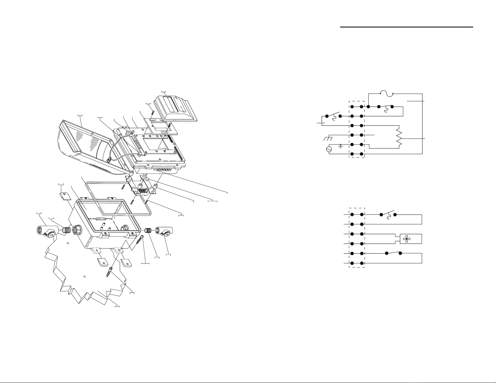
electrical check of the various components in the two voltage classes. The two
voltage classes are 24 VDC Negative Ground and 110 or 240 VAC 50-60 Hz with
connected electrical or earth ground. High voltage (110 or 240 VAC) wiring must
enter through bottom conduit. Low voltage and signaling wires must enter
through top conduit and remain separated per NFPA 70, NEC, and local codes.
4. If the thermal circuit breaker has tripped (opened circuit), the 110 or 240 VAC 50-
60 Hz power will still be energized up to the primary side of the thermal breaker.
For safety, disconnect supply power of conductors to three power circuits in the
enclosure.
5. To clean 24 VDC negative ground fan with electronic compressed air container,
disconnect all power.
Note: the 24 VDC negative ground fan will not operate if positive and negative
conductors are connected on the wrong terminals.
6. To minimize arid summer time heat build up in enclosure, install a dark color sun
shield with sides to provide shade for the enclosure. At the inclined face above
the enclosure at the point of contact with the building structure leave at least
1/2” or (1.25 cm) space. This will generate heat and cause an upward airflow
and help maintain the enclosure temperature approximately the same as
ambient air temperature.
7. The 110 or 240 VAC single phase 50-60 Hz heater does not require standby or
secondary power because the enclosure environment is supervised by a latching
supervisory circuit in the alarm control unit or panel.
8. Replacement of heater assembly and gasket is required five years from
installation date. Contact STI to order replacement Heater Kit STI-HK3.
9. All field wiring within this enclosure must be rated for a minimum operating
range of 0ºC - 110ºC.
The enclosure is used to protect UL Listed 38 and 2017 initiating devices at
temperatures down to -70˚F (-57˚C). It is the installer’s responsibility to comply
with NEC 70 Articles 725 and 760, NFPA 72, and other applicable fire and
electrical codes. Conduit or raceway paths need to be sealed as near to the
enclosure as possible. Installer should have maintained supervision over the low
temperature thermostat. The low temperature monitoring thermostat makes
the circuit at +32°F (0°C) and clears the circuit at +50°F (+10°C). This listing
requires that the fire alarm supervisory control module be only of the latching
type. On the appliance mounting plate is a label where you should record the
installation date. Also include below the serial number and installation date on
the instruction sheet for quick reference.
Serial Number ____________________ Installation Date ______________
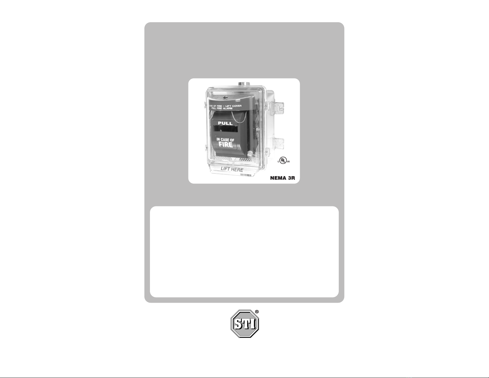
NOTE: Operating voltage for the STI-1200A-HTR is 110 VAC. Operating
voltage for the STI-1200A-HTR240 is 240 VAC.
3
Polycarbonate Cleaning Instructions
Rinse with water to remove abrasive dust and dirt. Wash with soap or mild
detergent, using a soft cloth. Rinse once more, then dry with a soft cloth or
chamois. Exercise caution when using water inside enclosure. Make sure unit is
completely dry inside before reassembling. Do not use razor blades.
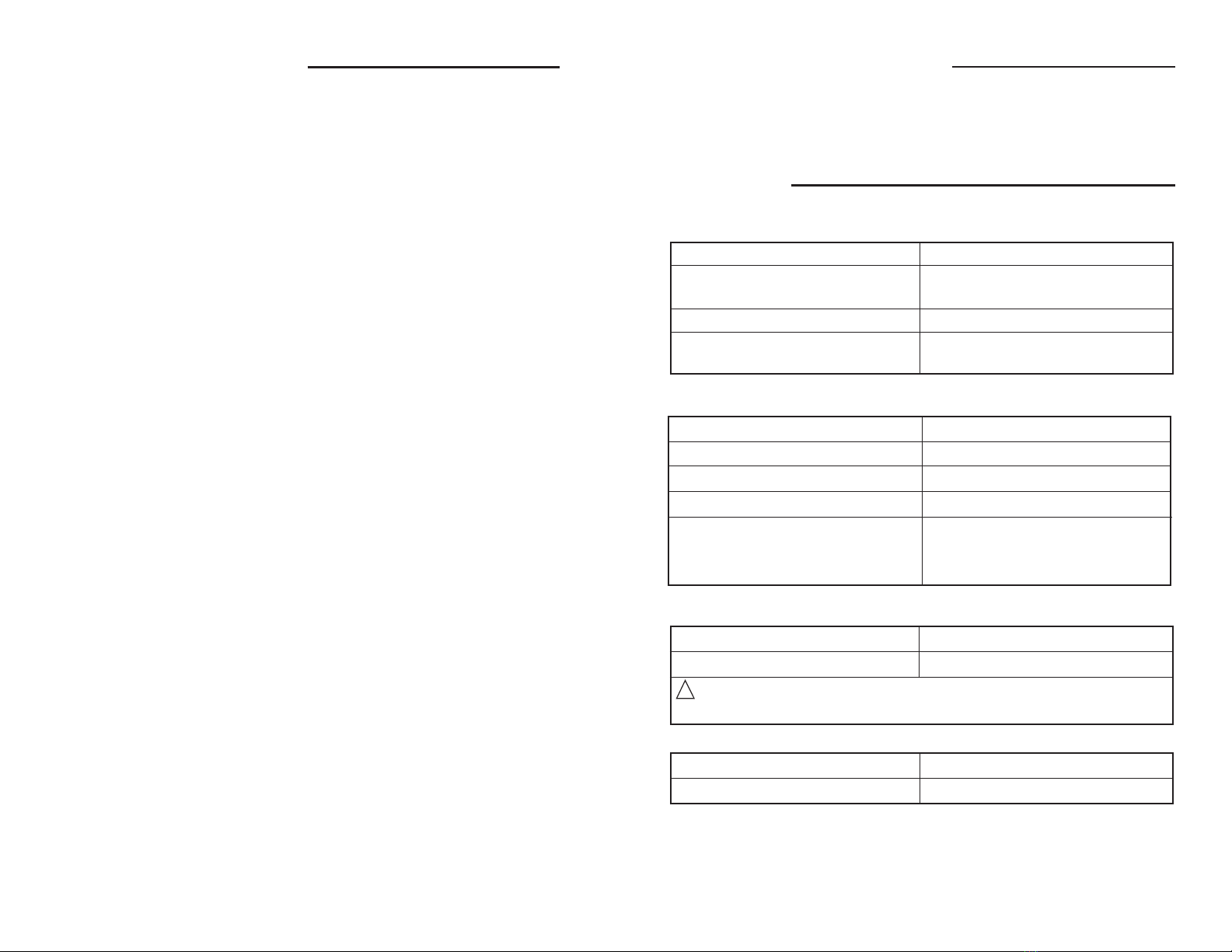
Specifications
Polycarbonate Enclosure:
Flammability: UL94 V-2
Wall Thickness: backbox: .20 inches (5.1mm)
cover: .12 inches (3.1mm)
NEMA Rating: 3R
Warranty: Lifetime against breakage in
normal use.
Silicone Laminate Heater:
STI-1200A-HTR 110 VAC 50/60 Hz UL Recognized Component
STI-1200-A-HTR240 240 VAC 50/60 Hz UL Recognized Component
100 Watts
Life: @ -10˚C (14˚F) ~ 70˚C (158˚F) 5 Years
Duty Cycle: -40˚F (-40˚C) 16%
-70˚F (-57˚C) 38%
-99˚F (-73˚C) 100%
Fan:
24 VDC (±10%), 90 mA UL Recognized Component
Life: 5 Years Continuous Duty
WARNING: The polarity of the circulating fan is important as it only
rotates in one direction with red lead being positive.
Gasket:
Material: Neoprene
Life: 5 Years
!

Installation Instructions
4
Mount Enclosure Backbox - Refer to Fig 1
1. Set heater assembly with cover aside. Press (4) plastic tabs into slots on
backbox and drill (4) 1/4” (6.4mm) diameter holes in mounting surface for
plastic anchors provided. Attach backbox to wall using (4) #10 x 1-1/2”screws
provided.
2. Attach 3/4” rigid conduit and conduit sealing hub (Crouse-Hinds 3/4” EYSX 21
or equivalent) to backbox. Conduit should be installed according to applicable
NEC and local codes.
3. Pull 24 VDC and alarm wiring into backbox through top conduit; and pull 110
or 240 VAC wiring into backbox through bottom conduit per NFPA 70, NEC and
local codes.
Note: Wire size to be 12-22 AWG.
Install Fire Alarm Pull Station and Dual Monitor Module to Heater and
Cover Assembly - Refer to Fig 2.
4. Lift the cover from heater assembly and allow it to hang from cables.
Connect the provided high temperature wires to the pull station.
5. Attach the pull station to the slide plate using (2) #6-32 x 3/8” screws
provided. Adjust the slide plate so the pull station or slide plate does not
cover either the fan opening or vent slots.
Note: If the fan opening or vent slots are covered, the plate mounting screws
can be moved to the alternate mounting position. After mounting pull station
adjust the slide plate so there are no gaps large enough to touch the heaters
behind the pull station.
8 7/16 in. (214mm)
4 3/8 in.
(111mm)
LOW VOLTAGE
WIRE INPUT
SEALING HUB
(NOT PROVIDED)
3/4 in. NPT MALE NIPPLE
(NOT PROVIDED)
MOUNTING TAB
(4) PROVIDED
BACKBOX
#10 x 1 1/2 in.
PAN HEAD SCREW
(4) PROVIDED
HIGH VOLTAGE WIRE INPUT
MOUNTING
SURFACE
SCREW ANCHORS
(4) PROVIDED
DRILL (4) 1/4 in. (6.4mm)
DIAMETER HOLES
3/4 in. NPT MALE
NIPPLE (NOT PROVIDED)
SEALING HUB
(NOT PROVIDED)
FIG. 1
5
Wiring
7. Wire one channel of the dual monitor module to the low temp warning
terminals (pins 1 & 2) on the 24 VDC terminal block. Wire the other channel
to the fire alarm terminals (pins 5 & 6) on the same terminal block. Add any
end of the line devices as required for the alarm system.
8. Connect wires from alarm panel to the dual monitor module according to
design specifications. Connect continuous 24 VDC supply to fan power
terminals (pins 3 & 4) of the 24 VDC terminal block.
Note:
1. Fan is polarity sensitive and must be connected correctly for fan to operate.
2. Fan operates continuously.
9. Connect the 110 or 240 VAC supply to the high voltage terminal block pins 4,
5, and 6. Earth Ground, AC Low, and AC High respectively.
10. Attach the heater and cover assembly to the backbox with (4) #8-32 x 3/4”
socket cap screws and (4) #8 flat washers.
11. Record installation date in space provided on the label located on underside
of cover. Unit is ready for testing.
12.Turn all power to “ON” position.
Note: Fan runs continuously. This system requires three sources of power:
1. 110 or 240 VAC heater on the load side of the fuse holder.
2. 24 VDC power source for the circulating fan. Check fan to see if
operating; if not check polarity and reverse, then try again.
3. Fire alarm initiating circuit and temperature warning monitor.
6. Turn assembly over and mount dual monitor module to the backside of the
heater assembly using (4) #6-32 x 1” screws and (4) 3/8” standoffs provided.
Replace cover.
FIG. 2
#6-32 x 1 in. PAN
HEAD SCREW
(4) PROVIDED
3/8 in. STANDOFF
(4) PROVIDED
DUAL MONITOR
ADDRESSABLE MODULE
(NOT INCLUDED)
24 VDC TERMINAL BLOCK
PULL STATION
(NOT INCLUDED)
#8-32 x 3/8 in.
FLAT HEAD SCREW
SLIDE PLATE
HIGH VOLTAGE TERMINAL BLOCK
FAN
WARM AIR DUCT (DO NOT COVER
WITH PULL STATION)
VENT SLOTS
(DO NOT COVER
WITH PULL STATION)
COVER AND HEATER ASSEMBLY
IN CASE OF
PULL
FIRE

Product Assembly
6
SEALING HUB
(NOT PROVIDED)
3/4 in. NPT MALE NIPPLE
(NOT PROVIDED)
MOUNTING TAB
(4) PROVIDED
BACKBOX
#10 x 1 1/2 in.
PAN HEAD SCREW
(4) PROVIDED
MOUNTING
SURFACE
SCREW ANCHORS
(4) PROVIDED
#6-32 x 1 in. PAN HEAD SCREW
(4) PROVIDED
3/8 in. STANDOFF
DUAL MONITOR
ADDRESSABLE MODULE
(NOT INCLUDED)
LOW TEMP WARNING
THERMOSTAT
24 VDC TERMINAL BLOCK
PULL STATION
(NOT INCLUDED)
#8-32 x 3/8 in.
FLAT HEAD SCREW
SLIDE PLATE
HIGH VOLTAGE TERMINAL BLOCK
FAN
CIRCUT BREAKER
COVER AND
HEATER ASSEMBLY
IN CASE OF
PULL
FIRE
GASKET
3/4 in. NPT MALE NIPPLE
(NOT PROVIDED)
SEALING HUB
(NOT PROVIDED)
7
Schematic Diagrams
2 AMP CIRCUIT BREAKER
OVERTEMP SAFETY
1
2
4
3
5
6
CONTROL
110 OR 240 VAC
SINGLE PHASE
1
2
4
3
5
6
FAN
PWR +
_
FAN
LOW TEMP WARNING
(16-33VDC 600mA)
LOW VOLTAGE CIRCUIT
HIGH VOLTAGE CIRCUIT
TERMINAL
BLOCK
TERMINAL
BLOCK
CHASSIS
HEATER
CLOSE @ 40˚F (4˚C)
OPEN @ 65˚F (18˚C)
OPEN @ 120˚F (40˚C)
CLOSE @ 80˚F (27˚C)
OPEN @ 50˚F (10˚C)
CLOSE @ 32˚F (0˚C)
24VDC (±10%), 90mA
FROM MONITOR MODULE
TO TEMP WARNING
FROM MONITOR MODULE
TO MANUAL STATIONS
EARTH GROUND
MANUAL STATIONS
110 OR 240 VAC
50/60 Hz
100 WATTS

Printed in USA Inst. Sht. 1200A HTR MARCH2006
Safety Technology International, Inc.
2306 Airport Road
Waterford, Michigan 48327-1209
Phone: 248-673-9898 • Toll Free: 800-888-4784 • Fax: 248-673-1246
Safety Technology International (Europe) Ltd.
Unit 49G Pipers Road • Park Farm Industrial Estate • Redditch
Worcestershire • B98 0HU • England • Tel: 44 (0) 1527 520 999
Fax: 44 (0) 1527 501 999 • Freephone: 0800 085 1678 (UK only)
www.sti-usa.com
This manual suits for next models
2
Table of contents
Popular Fire Alarm manuals by other brands

Siemens
Siemens FireSeeker FS-250 operating instructions

SL
SL SECURI4 Installation, operating, & maintenance instructions

Honeywell
Honeywell NOTIFIER AM-8000 installation manual

Notifier
Notifier ID50 SERIES installation, commissioning & configuration manual

First Alert
First Alert FA2000C user manual

Notifier
Notifier AM2020 manual