Characteristics
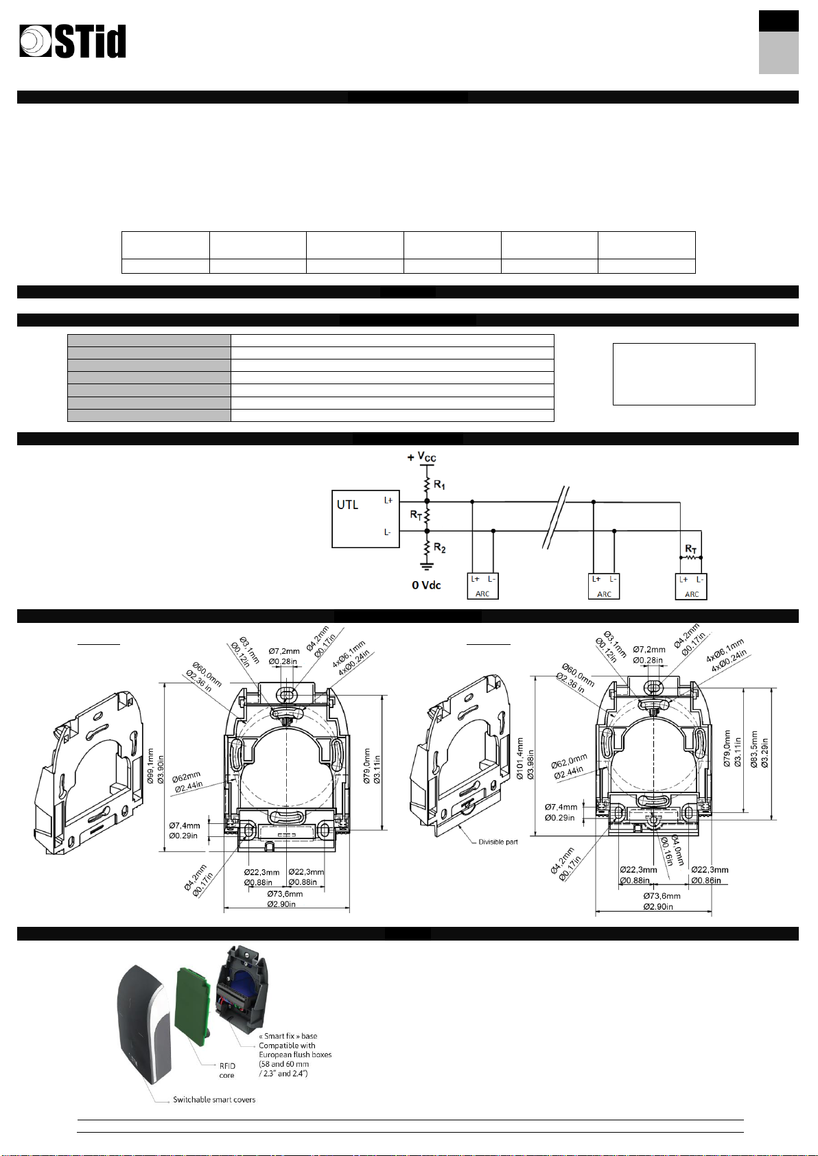
Communication: RS485 (L+ & L-) / RS232 (TD & RD) / TTL (Wiegand / Clock and Data)
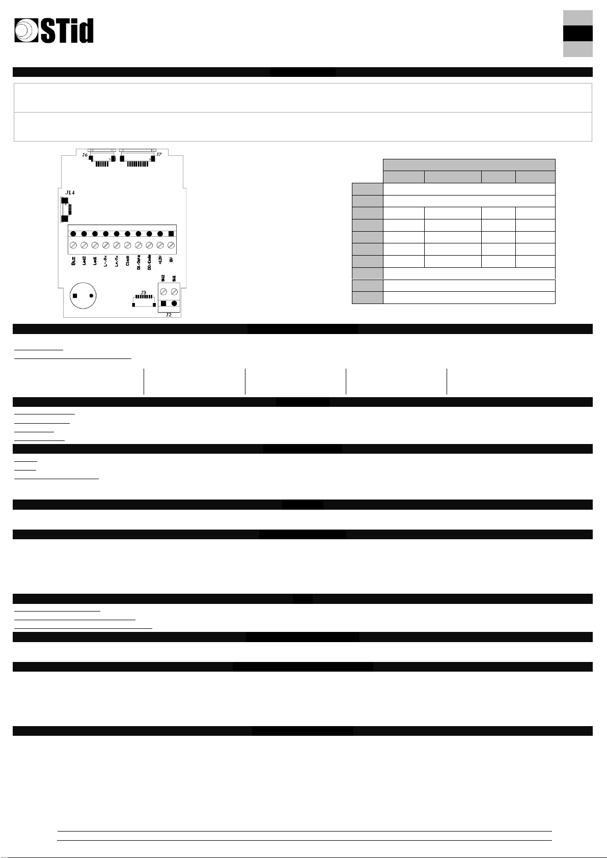
Connection: Removable connectors 1x10 pins and 1x2 pins, thread 0.19685 inch
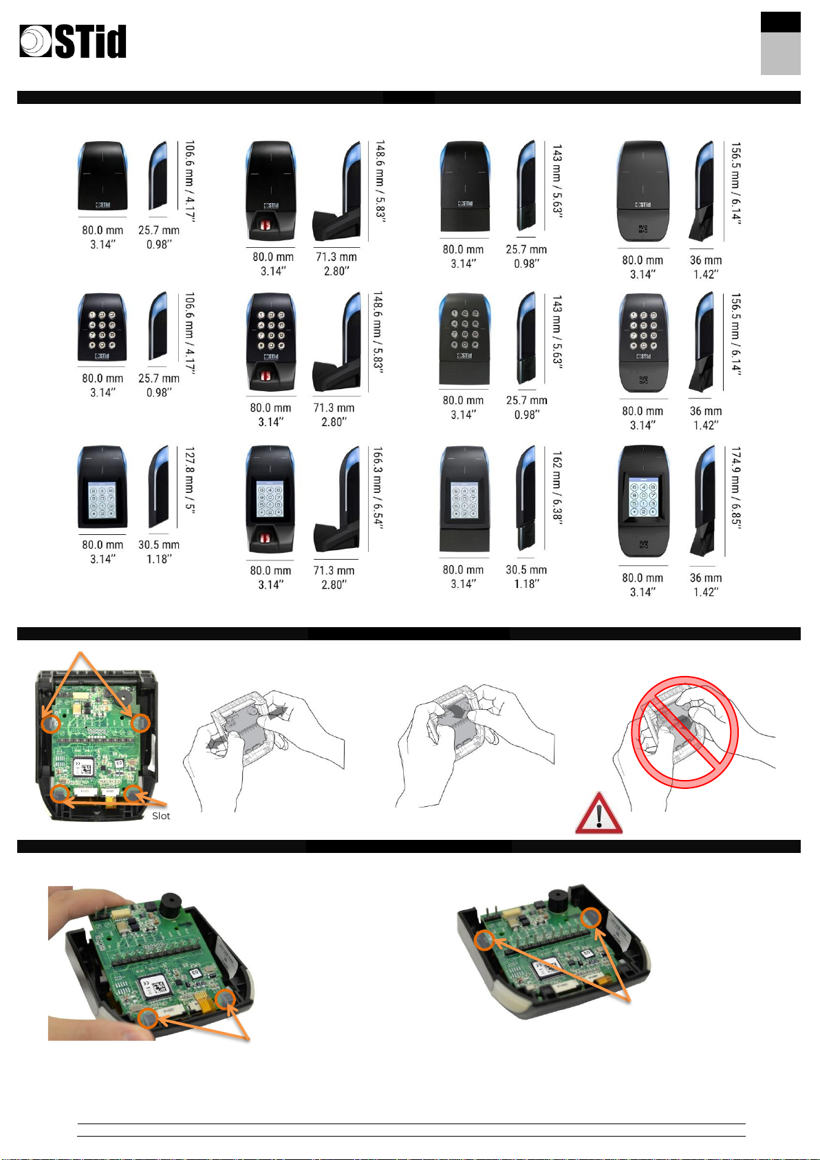
Protection: IP65 classified reader
Static relay: ASSR-1218-003E: 60 V output withstand voltage / 0.2A current rating / low on-resistance 1 Ω typical for AC/DC
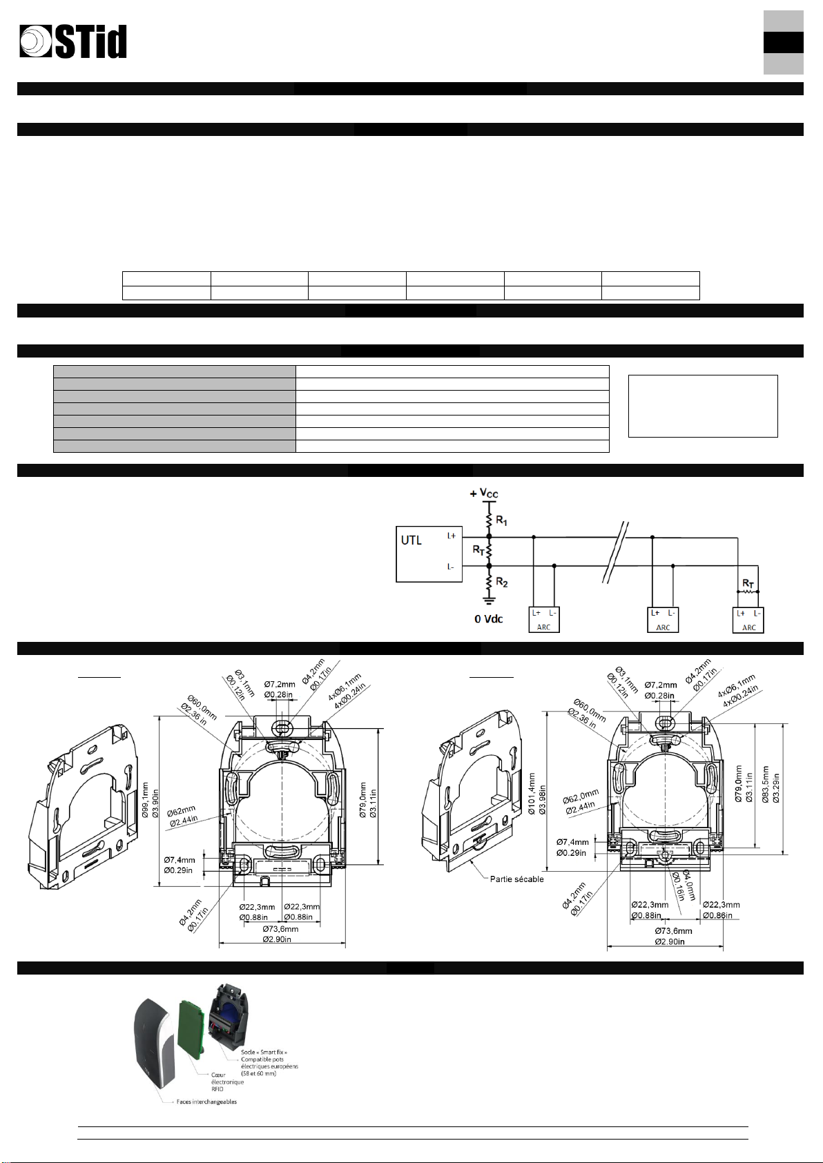
Recommended cables
RS485: Use a multi-conductor shielded twisted pair cable. Max. length: 3281 ft at 9600 baud
RS232: Max. length 49.2 ft
Wiegand / Clock & Data: Use an untwisted shielded multi-conductor. For data:
2 wires AWG24 –98 ft max / 4 wires AWG24 –197 ft max / 6 wires AWG24 –328 ft max
2 wires AWG20 –164 ft max / 4 wires AWG20 –328 ft max
Buzzer / LED
The operating mode for the Buzzer and LED 1 and 2 can be programmed by a configuration card (SCB / OCB) or controlled by the remote system with a 0 Vdc
respectively on the “Led 1”, “Led 2” and “Buzzer” inputs of the reader’s connector or controlled by the communication protocol of the reader (SSCP®/ OSDPTM).
Anti-tearing
Tearing is detected by an accelerometer. When the reader is wrenched, the switch output (connector J2) provides an O/C contact to indicate the tearing of reader.
▪for R/S 31/x1: the wrenching signal will be emitted on the “Data/Data1” line. This function is configurable via a configuration card.
▪for R/S 32/33/x2/x3 and OSDPTM: the reader will perform the operations configured with the configuration card.
▪for W 32/33/x2/x3: the reader will perform the operations configured with the SSCP® protocol.
Caution: switch on the reader when it is in its final position to initialize the accelerometer in the correct position.
Relay
Read-only reader: automatic tamper management (except touch screen) or activated on the reading of a valid identifier
Touch screen read-only reader: if the bell is activated, contact J2 is used to connect the external ring (max. 200 mA at 28 Vdc).
Read/Write & OSDPTM readers: the relay is controlled by the SSCP®/ OSDPTM protocol commands.
UHF default configuration settings
Reader powered off. The defaults reader settings can be stored in internal memory accessible by UHF RFID technology. They will be taken into account when the
reader is powered on.
Read-only reader configuration
R and S readers are configurable with SCB RFID configuration card.
OSDPTM readers are configurable with OCB RFID configuration card or with FileTransfer command.
▪If the SCB/OCB is compatible with the reader’s firmware, the LED lights green and the buzzer beeps five times.
▪If the SCB/OCB is not compatible with the reader’s firmware, the LED lights red and the buzzer is activated for 1 s.
▪If the SCB/OCB key is different from the reader’s key: no reaction.
Caution: set your reader with your own company key.
Powering-up the readers
On power-up, the reader enters an initialization phase:
1. Activation of the white LED and buzzer for 100 ms.
For read-only and OSDPTM readers:
2. Activation of the LED, according to the color code: Red = +10, Orange = +5, Green = +1, indicating the firmware version.
3. For serial R/S ARC only: the orange LED flashes 20 times: waiting for an update.
4. Activation of the default LED (read-only: flashes blue, OSDPTM: off; if no customer specific configuration).
5. For the ARC screen with an activated keypad, the default mode is displaying the picture on standby and activate the keyboard by pressing the screen.
Precautions for the biometric sensor and keypad
▪For optimal operation, the biometric sensor must be free of all traces of water. Outdoors it is recommended to install the reader under cover.
▪The keypad is sensitive. Take off your gloves to enter your code.