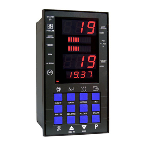
Stienen B.E. CLK-20 User manual

USER MANUAL
CLK-20(-i) CLOCK CONTROLLER
EN
© StienenBE / CLK-20-G-EN02020

Shut down power before opening the clock controller!
The clock controller contains exposed live parts!
Only to be opened by authorized personnel!
WARNING
Although utmost care has been given to the quality of this equipment during the design and manufacturing stages,
technical malfunctions can never be ruled out. The user should ensure that an adequate alarm system
and/or emergency provisions is/are in place to prevent any technical failure of the equipment and
peripheral facilities leading to danger to people, animals or property.
IN THE EVENT OF AN EMERGENCY, NOTE DOWN THE FOLLOWING
●Hardware and DIP switch settings
●Circumstances in which the emergency occurred
●Possible causes
●Software version number
Please contact our Customer Service Department, if you have any questions. Be sure to have all necessary data at
hand. To ensure a speedy solution to the malfunction and to avoid any misunderstandings, it is advisable to note
down the cause and the circumstances in which the malfunction occurred before contacting us.
No part of this document may be reproduced or transmitted in any form or by any means, electronic or
mechanical, for any purpose, without the express written permission of StienenBE (www.StienenBE.com)
StienenBE does not accept any liability for the contents of this manual and explicitly waives all implicit guarantees
of merchantability or fitness for a certain use. StienenBE also reserves the right to improve or change this manual
without being under the obligation to inform any person or organisation of any such improvement or change.
StienenBE cannot be held liable for any damage, loss or injury resulting from improper use or from use not in
accordance with the instructions in this manual.

INTRODUCTION 4
Screen 4
Scroll window 4
Operation 4
Numerical keys (0..9) 5
Function keys (graph, alarm, previous / next control etc.) 5
Navigation keys (menu, cursor, mode) 6
MAIN MENU 6
Access code 6
TIMERS 7
Timers 7
Master timer 7
Standard timer 8
Fixed time schedule number 8
Variable time schedule number. 8
Light timers+ 9
Timers 11
Sequential timers 11
Nest box timer 11
Time schedules 12
Time schedules 12
Light schedules 12
Growth curves 12
Date/Time 13
Timer overview 13
Alarm 13
ALARM 14
Latest alarms 14
Communication alarm 14
Alarm codes 15
SYSTEM 16
DISPLAY 16
Remote control 16
Application notes
Data communication
ANote-DataCom-N-ENxxxxx
Remote control
ANote-Remote-N-ENxxxxx
Skylights
ANote-Skylights-N-ENxxxxx
xxxxx = application note version number.

Page 4 of 16
INTRODUCTION
SCREEN
When the symbol is shown in the title bar and you press function key F3, the settings are displayed
graphically. Press F3 again to switch off the graphic display. Whenever a key is pressed, the screen will be lit for
a couple of minutes so that you can also see the settings and measurements in a dark animal house.
SCROLL WINDOW
If a window contains more lines than the screen can display, the title bar will show the symbol. This symbol
indicates that you can call up the remaining settings and/or measurements using the up and down cursor keys
().
OPERATION
2
Note!
Only press the keys with the tip of your
finger. Sharp objects can damage the
keyboard!
The keyboard can be divided into three
basic groups:
1. Numerical keys
2. Function keys
3. Navigation keys
3
1
Adding or removing a period
1. Press the [Enter] key (edit mode)
2. Press and hold the [F1] function key and then press the:
3. [+] key to add a breakpoint/period (provided that the maximum value for periods/breakpoints has not been
reached)
4. [-] key to remove a breakpoint/period (provided that there is at least one period/breakpoint)
The number of breakpoints/periods is adjusted automatically.
The calculated setting may
differ from the value set by the
user, due to the growt
h curve
and/or compensations.
Screen number
Title bar
Column with settings and/or
Column with calculated
and/or corrected settings
Graph (function key F3)
Time & Date
You can use the
key to select
the previous control number.
You can use the
key to
select the next control
number.

Page 5 of 16
1
NUMERICAL KEYS (0..9)
The numerical keys can be used to enter a
screen number or edit a setting or a text.
Entering text (installer mode)
The numerical keys 2..9 can be used to edit
the name of a timer. The maximum text length
is 15 characters (including spaces). The
character you enter is shown in a little box.
Press the numerical key repeatedly until the
character to be selected is shown. You can
enter a punctuation mark by repeatedly
pressing numerical key 1 until the relevant
punctuation mark is shown. You can enter a
space using the 0 key.
Press once for a, twice for b, etc. You can use the and keys to move the cursor. Where relevant, e.g. for
menu options etc., the text will automatically start with an initial capital.
2 FUNCTION KEYS (GRAPH, ALARM, PREVIOUS / NEXT CONTROL ETC.)
Function key F1 (change language)
Changing language: Press and hold function key F1 and use the left or right arrow key to select the
relevant language.
Function key F3 (graph)
Use this function key to place a graph in a screen. The “graph” function is active when the LED in the
function key lights up. You can switch off the “graph”
function by pressing the function key again (the
LED in the key is off then).
The values in a graph are linked to the screen on the basis of which the graph was drawn up. The graph is
updated automatically when you change the details on the screen.
If the details in the screen are displayed in graph form, the symbol will be displayed in the top right corner of
the menu line.
Select previous/next control
Select next/previous timer, time schedule, etc.
Alarm key
Short key for alarm screens The LED in the alarm key lights if one of the controls has an alarm
situation.
You can switch the main alarm on or off in this screen. The LED will blink at a steady frequency if the main
alarm is off. No alarms will be generated then.
Test (alarm test)
Test
“yes”:This enables you to test the operation of the alarm relay
(siren). If you enter "yes" in the
Test line, the alarm relay (siren) will be
switched on for 10 seconds.
You can clear the alarm test time by setting "no" in the
Test line.
(alarm temporarily off)
Off:
“yes”: This enables you to temporarily switch off the alarm (siren).
This does not apply to the hardware alarms; they cannot be switched off
temporarily.
deféèêë3DEFÉÈÊË
abcàâæç2ABCÀÂÆÇ
mnoñôöœ6MNOÑÔÖŒ
jkl5JKL
wxyz9WXYZ
tuvû8TUVÛ
.,1'-:+
ghiîï4GHI
ÎÏ
pqrs7PQRS
_0

Page 6 of 16
The main alarm is switched off for 30 minutes (the LED will blink irregularly). The main alarm is switched on
automatically again after 30 minutes. The alarm relay will de-energize again, causing an alarm, if the cause of
the alarm has not been removed.
You can clear the temporary alarm deactivation time by setting "no" in the line.
If no access code has been installed on the CLK-20, or if you have already entered the correct access code, you
can switch off the main alarm.
Attention
NEVER FORGET TO SWITCH THE ALARM BACK "ON" when you have switched this feature
off 'temporarily', e.g. to solve a problem. Failing to switch it back on may have adverse effects
for people, animals, equipment or property.
Preferably use the (alarm temporarily off) function to solve a fault.
3
NAVIGATION KEYS (MENU, CURSOR, MODE)
Cancel
This key cancels changes or menu option selections.
Press and hold this key to select the main menu.
Move cursor
Move cursor
Pressing and holding the key: move cursor to the first/last setting on the screen.
Move cursor or change value
Confirm
•Menu option
•Start change
•Confirm change
•The cursor is displayed as a green rectangle, e.g. .
•While a change is being made, the cursor is displayed as a black
border, e.g. .
MAIN MENU
If you use an
access code, it is advisable to write the code down and store
it somewhere safe. If you forget the access code, you can no longer
change any settings. As soon as one access code is active, you can only
change the setting by entering the correct access cod
e. As soon as one
access code is active, you can only change the setting by entering the
correct access code. The access code remains active until you select the
“
Overview” screen.
ACCESS CODE
You can use access codes, e.g. to protect your computer against unauthorized access. If you want to prevent
non-authorized users from changing the settings on your clock controller, you can have an access code set. An
access code consists of a combination of 4 digits. You can have a maximum of 2 access codes set by your
installer.

Page 7 of 16
TIMERS
A maximum of 24 periods can be set on a timer. All times have to be
consecutive times. The difference in time between any two times should
be at least 1 minute. If you a
re using a growth curve (“growth curve
schedule
”
), you can automatically activate another schedule, depending on
the ages of the animals. You can also link the timer to the
“master timer”.
The master timer is a timer that
synchronises the slave timers. If you set
“
on” for a timer, instead of setting “slave”, the times will be related to the
master timer
(however, you can still correct the start (‘Begin’) and end
times locally for the individual timers then).
Linked lighting schedules are used with light timers whose settings are interrelated. In that case, the master
timer is used in order to be able to quickly synchronise the timers. If, for example, the feed and water times
vary within a short period of time (some days/weeks), different time schedules can be used. Preprogramming
the different time schedules enables a quick change-over between schedules.
TIMERS
You can choose from the following
timers:
•
“Standard timer” (with its own
local times, not linked to a time
schedule) or
•
“Master timer” (you are using
time schedules; the times are
linked to a time schedule).
Standard timer
The number of periods and the times are set locally (in the timer's “own” screen).
Master timer
Fixed
time schedule number
You cannot change either the number of periods or the period times locally; these
settings are copies of the schedule number entered (time, light or dosing schedule).
You can choose from a maximum of 6 different schedules
Variable
time schedule number
You cannot change either the number of periods or the period times locally; these
settings are copies of the current schedule number resulting from the growth curve
(time, light or dosing schedule). However, if
“none” has been set under Schedule in
the growth curve, the local times will be used.
MASTER TIMER
4
4
Standard timer (not linked to a time schedule
number)
With a fixed time schedule number
With a variable time schedule number

Page 8 of 16
STANDARD TIMER
FIXED TIME SCHEDULE NUMBER
You cannot change either the
number of periods or the period
times locally (these settings are
copies of the preset time schedule
number).
You can only change the number of
periods and the period times in the
preset time schedule number (in
this example this is “Time schedule
1”).
VARIABLE TIME SCHEDULE NUMBER.
The settings in the two examples above are copies of the central time schedule resulting from the curve. Note!
However, if “no” has been set under Schedule in the growth curve, the local times will be used.
Local times

Page 9 of 16
LIGHT TIMERS+
Light control
Light timers enable the use of light control to gradually switch the lights on/off. A light control enables you to
create optimum day and night conditions (dawn switch).
Standard light schedule
80%
100%
1
3
4
10%
20%
2
1. The lights will go on at the time set for point 1 (05:00) and the light intensity will be controlled to 20%
within a period of 4 minutes ( :04).
2. The light intensity will be controlled to 80% within a period of 20 minutes ( :20) at the time set for point
2 (05:20).
3. The lights start to dim at the time set for point 3; the lighting intensity is lowered to 10% within a period of
30 minutes ( :30) and the lag time starts.
4. The lights switch off at the time set for point 4.
Fixed light schedule number
Variable light schedule number

Page 10 of 16
Light control in combination with the master timer
If you set more than 1 period for the master timer, the “Light intensity” settings will apply to all periods of the
master timer.
Begin/End times correction
You can correct the actual
“Begin” and “End” times (last column) by
entering a correction under the
“Begin” and “End” times (first column).
The maximum cor
rection allowed is +or - 8:00 hours). This may be
necessary, for example, to use the master timer for several time processes
with the same number of periods.
Inspection light
4
The light can be switched on manually, using a pushbutton, in order to
in
spect the houses. The light will then be switched on for a certain time
(this can be set by the installer). If the pushbutton is pressed again during
the
“On period”, the lights will switch off again immediately.
80%
100%
1
2
3
10%
1 Dimtijd licht aan
2 Dimtijd licht uit
3 Nabrandtijd
Begin
Eind

Page 11 of 16
TIMERS
These timers are “On/Off” timers. If a master timer has been installed, you can link these timers to the master
timer (slave mode timer). If the timer has not been linked to the master timer, you can use time schedules (or a
growth curve consisting of time schedules).
Standard timer
You can correct the actual
“Begin” and “End” times (last column) by
entering a correction under the
“Begin” and “End” times (first column).
The maximum correction allowed is
+or - 8:00 hours). This may be
necessary for example to use the master t
imer for several time processes
with the same number of periods.
The timer is linked to the “Master timer”
SEQUENTIAL TIMERS
These timers are used for such procedures as controlling feed chains or rinsing water pipes. You can only set the
start time (Begin) for a sequential timer; the end time is determined by the total pulse/pause time and the
number of outputs.
In case of a sequential timer, the different outputs assigned to the timer are activated in sequence, after each
other. An output is not activated until the previous output is no longer active. The different actions that are
carried out in sequence are also called phases or steps.
NEST BOX TIMER
The CLK-20 has a timer with on/off times for opening or closing the nest
boxes. The nest box can even be opened and closed with intervals
(according to a pulse/pause principle). Your installer sets the pulse/pause
times, so that the nest box will open or close at the speed you require.
The nest box timer is set according to a standard timer, see “Timers”.

Page 12 of 16
TIME SCHEDULES
TIME SCHEDULES
You can set a maximum of 9 different time schedules. Every time schedule can have a maximum of 24 periods.
LIGHT SCHEDULES
You can set a maximum of 9 different light schedules. Every light schedule can have a maximum of 48 periods.
GROWTH CURVES
You can include the time schedules in a growth curve. When the day number is reached, another time schedule
will be selected. If no has been entered for a breakpoint, the times of the original timer will be used.
Note!
•The day numbers in the curve have to be consecutive numbers.
•If the day number of the first breakpoint is greater than 1, the setting for the first breakpoint
will be maintained until the preset day number.

Page 13 of 16
DATE/TIME
In addition to the date and time, you can set the time when a new day starts at “Beginning new day”.
Be careful when changing the “Beginning new day” setting; if this time is in a dosing period the
“Conflicting periods” error message will be generated.
TIMER OVERVIEW
Graphic view of the timers.
ALARM
Besides the alarm status, the
current control signal sent to the
nest box and the nest box status
are displayed.
Menu 5 (“Alarm”) will show only if a nest box timer has been installed.

Page 14 of 16
ALARM
You can switch the main alarm on or off in this screen. The LED will blink at a steady frequency if the main
alarm is off. No alarms will be generated then.
Test (alarm test)
Test “yes”: This enables you to test the operation of
the alarm relay (siren). If you enter "yes" in the Test
line, the alarm relay (siren) will be switched on for 10
seconds.
You can clear the alarm test time by setting "no" in
the Test line.
(alarm temporarily off)
Off “yes”:This enables you to temporarily switch off
the alarm (siren). This does not apply to the hardware
alarms; they cannot be switched off temporarily. The
main alarm is switched off for 30 minutes (the LED
will blink irregularly). The main alarm is switched on
automatic
ally again after 30 minutes. The alarm relay
will de-energize again, causing an alarm, if the cause
of the alarm has not been removed.
You can clear the temporary alarm deactivation time
by setting "no" in the line.
Note
NEVER FORGET TO SWITCH THE ALARM BACK "ON" when you have switched this feature off
'temporarily', e.g. to solve a problem. Failing to switch it back on may have adverse effects for
people, animals, equipment or property.
Preferably use the (alarm temporarily off) function to solve a problem.
Installation errors such as “Output already assigned”, “Incorrect output type”, “Input
already assigned” etc. have to be solved first before putting the system into operation.
LATEST ALARMS
The last 5 alarm causes which caused the alarm relay to de-energize are stored. The dates and times of the
alarms are displayed in addition to their causes.
Alarm 0:
The cause of the most recent alarm is displayed at “Alarm 0”, in addition to the time until which
the alarm has been/was active.
Press the down arrow key to display the data of the previous alarms.
COMMUNICATION ALARM
You can switch the communication alarm on or off in this screen. This
screen is displayed only with a master device.
“
Device address” is followed by the address from which the master
device has not received any data.

Page 15 of 16
ALARM CODES
Alarm code
Description
Alarm unknown (xxx)
This alarm code cannot be translated into a text. Note down the number that
is displayed and contact your supplier.
Beginning day in period
The “Beginning new day” time is in a period; this is not allowed. The
“Beginning new day” time MUST be BEFORE the first period.
Module x changed
Module configuration (inputs/outputs etc.) changed. Read in the module
number again.
Wrong input type
The input type set does not match the input type based on which the control
can control.
Wrong output type
The output type set does not match the output type that the control can
control.
Unknown terminal type
Faulty assignment. The function that you assign to the terminal is not
supported by the module.
No communication address
Device address CLK-20 is missing.
Invalid period
•The times set for a timer must be ascending and the difference between
“Begin” and “End” must be at least 1 minute.
•The following applies to a light control: the begin time + the run time
must not be after the next begin time (but the time is allowed to be at the
same time as the next begin time).
No input assigned
No input terminal number entered.
No info from houses
•Software version in CLK-20 is not up to date, update software.
•The house is not in use.
No output assigned
No output terminal number entered.
Input already assigned"
The input has been assigned to two or more controls.
Module not found The module number set for the terminal does not exist.
Module not found
Module address not found, check the settings on the module.
Module x reset alarm
Module continues to reset due to a fault, check the module.
Unknown terminal type
The selected type of terminal does not exist.
Invalid input
The input number does not exist on the module.
Invalid output
The output number does not exist on the module.
Conflicting periods
The 'Conflicting periods' error message occurs if 1 or more feed dosing timers
have to be active at the same time.
Output already assigned
The output has been assigned to two or more controls.

Page 16 of 16
SYSTEM
This screen shows the device name, the device type (172=CLK
-20), the
program version, program date and other infor
mation.
Set the language to ENG (English) for this manual. You can also change
the language by pressing and holding functional key F1 while
simultaneously pressing the left or right cursor key.
DISPLAY
Brightness
To set the brightness of the background lighting
on
To set the brightness of the active situation (operating mode).
off
To set the sleep mode brightness.
On-time
Number of seconds during which the screen is lit after the last time a key is pressed.
Setting 0 seconds does not switch off the screen lighting.
Cursor left
“Yes”: when changing a setting, the cursor is placed on the digit which is the furthest to the left.
“No”: when changing a setting, the cursor is placed on the digit which is the furthest to the
right.
REMOTE CONTROL
Remote control:
See “Application note Remote control: ANote-Remote-
N
-ENxxxxx”
This manual suits for next models
1
Table of contents
Popular Controllers manuals by other brands
CellGate
CellGate UNIFY CWE-U320 Quick install guide
Siemens
Siemens SIMOTION Series Commissioning and hardware installation manual

Black Stone
Black Stone BL 982411-0 instruction manual
TCS Basys Controls
TCS Basys Controls QD Series Troubleshooting Worksheet

Mitsubishi Electric
Mitsubishi Electric Q Series Programming manual
Full Gauge Controls
Full Gauge Controls TC-900i power Operation instructions
